Licensed drawing programs. Drawing program sPlan - repair assistant
Good day to all readers! This time we will digress a little from the actual construction topic. Today I bring to your attention the most useful drawing program.
It's called sPlan (currently the seventh version is current). When renovating, very often you need to draw something, design something, and draw up a floor plan. This thing allows you to do all this easily and quickly.
Here's why I personally use it in my work:
- Creation of apartment/room plans with all sizes and areas included
- Designing plasterboard structures, especially useful for calculating rounded shapes
- Drawing up a wiring plan
- Drawing up visual diagrams for counting material
Using a computer program for these purposes is much more convenient than drawing everything by hand on paper.
sPlan makes it easy to make any adjustments to drawings, export them to common image formats and print everything. But the most important advantage of this program is its simplicity. At the end of the article I will give specific examples of my drawings and what was done with them.
sPlan, in fact, is designed for drawing up electrical diagrams, but we will consider it only as a program for creating drawings.
General information about this drawing program
sPlan is a German product from ABACOM. It works for everyone operating systems from Microsoft, starting with Windows 2000 and ending with Windows 8. Contains many built-in object libraries: all kinds of capacitors, transistors, etc., but we don’t need that. All components, shapes, lines are snapped to the sheet grid, the size of which is specified by the user. The program supports cutting, copying and pasting objects, applying dimensions: linear, angular, radial. This is what the working window looks like:
On the left is a field for selecting ready-made components; its width can be changed, but we are not interested in it. To the right of it is a column of working tools for creating and editing a drawing: (from top to bottom) pointer, rectangle, circle, special shape, shape, line, Bezier curve, dimensions, node, text, text block, drawing, magnifying glass, meter. We'll talk about them a little later.
The largest field, of course, is the drawing area, and at the bottom of the window there is a status bar, which displays: (from left to right) cursor coordinates, scale, grid size and magnification, settings for aligning and joining objects, bending and rotation angles, line settings and figures, tips. The program has the ability to create several sheets of drawings in one file, similar to Microsoft Excel.
Settings
All basic sPlan settings are located in the Options/Default Settings menu: 
Here are the main ones:
- Numbering of sheets. On the tab next to the sheet name there will be its number. A matter of taste.
- Numbering of elements taking into account the sheet number. Before letter designation element will be automatically assigned a sheet number. We don't need this.
- Text smoothing is a desirable thing, because when this function is turned off, the text in the drawings looks non-ice.
- Show ruler. Similar to MS Word. A handy thing that makes it easier to navigate the scale of the drawing.
- Ruler on a white background. Change the ruler color to white. Essential Function(sarcasm).
- Snap to grid. Must be included in mandatory, without it it is completely impossible to draw.
- Line sticking. The function allows you to save connections between circuit components in the program when moving one of them. Must be enabled.
- Joining the ends. As soon as we approach the end or starting point graphic element to the same similar end of the other, their ends will automatically join. A red square at the connection point will indicate that the common point of connection between the ends of the elements is captured. Definitely put it in.
- Compress the picture file when writing. If the drawing contains raster images, the program will compress it. Leave a checkmark.
- Windows FileInfo support. Saving information about files that reference a document. No need.
Font settings look like this: 
I use a drawing font, so everything looks more serious, I even printed my diploma with it, although everyone was perplexed as to why, but I got a 5. I use the same settings for texts and text blocks. We will not need fonts for contacts, symbols and denominations.
Grid Settings: 
A mesh size of 0.5 mm is almost always enough for me; more is not the same accuracy, less is inconvenient. The grid size change step in sPlan is 0.1 mm. A grid marker is a gradation of its lines. Number 5 in in this case means that every fifth line will be thicker than the rest, this is very convenient.
Size settings: 
Dimensions are always needed when drawing up any drawings. Again, I have a drawing font here, only the color is not black, but gray (you can choose any one). “The end of the arrow” implies the angle of its divergence, its sharpness. The size of the arrow is its length; everything else here, I think, is clear.
We don't really need the rest of the settings. Let's now talk in more detail about creating drawings.
Creating Drawings

The first thing you need to do after creating a blank drawing in the sPlan program is to set the sheet format and dimensions.
This is done through the Sheet/Properties menu item, or by right-clicking on the sheet tab and clicking Properties. Sheet formats (A0, A1, A2, A3, A4...) are known to everyone, you can choose one of them in vertical or horizontal orientation. And you can set the sizes yourself. I always put A0, it’s definitely enough for any drawing. In the same menu you can set the name of the sheet and its description.
So, we consider that we have created the drawing file, we have adjusted all the parameters to suit ourselves, we can start drawing. To begin with, I propose to consider the tools available for this. We look at the vertical toolbar. After the pointer there is the “Rectangle” tool, we’ll start with it, but first we must indicate its properties in the status bar:
 Here you set the thickness of the rectangle outline, its appearance, color, you can draw with a fill inside the outline and choose from several options for this fill. Let’s say we don’t need to change anything, we’re happy with everything anyway. Click OK and we see how the cursor has some kind of axes, they are very helpful in navigating the ruler:
To start drawing, you need to hold down left key and drag the mouse diagonally. We see that a rectangle emerges: 
The status bar (left) shows two pairs of coordinates. The left pair shows the absolute coordinates of the mouse cursor in the drawing, and the right pair shows its coordinates relative to the upper left corner of the figure. That is, we get a rectangle with sides 91x52 mm. The cursor axes have Blue colour, and in places where they overlap the lines of the figures they are painted yellow. Release the left mouse button - the rectangle is ready: 
We see that it is purple, and at the edges it is surrounded by squares of black and white flowers. This means that our rectangle is selected. If you pull the black squares, the figure will stretch in size in the corresponding directions, and if you pull the white squares, the corners will be smoothed out: 
Any shape or line in sPlan can be selected and modified in the same way. Selection is carried out by a single click with the left mouse button on the figure. There is another type of selection - by another click on an already selected object: 
In this case, the black squares turn into arrows, by grabbing which we can rotate the figure. The rotation is carried out not smoothly, but in steps; the gradations of the rotation angle can be changed in the status bar (green arrow): 
With the Circle tool everything is exactly the same, but rotating it doesn’t make sense. In general, using this tool, we get general case ellipse, and to get exactly a circle, we need to hold down the left mouse button together Shift key(in some versions of the program, for some reason Ctrl, look at the prompts in the right corner of the status bar): 
With circles in sPlan you can do one interesting thing- open them, turning them into arcs. When designing multi-level plasterboard ceilings or figured partitions this function very useful. The white square on the rightmost point of the circle when selected is responsible for it. Pull it down - the circle opens, upward - an arc of the same radius appears instead: 

“Special Figure” has four options: Polyhedron, Star, Table and Sine. 
All options are customizable, but the need to use them is extremely rare.
"Figure" (or "Polygon"): 
One click of the left button starts drawing, each subsequent click specifies a vertex at a given point, and stopping drawing is done by clicking the right mouse button.
“Line” - this tool is used, perhaps, more often than others. Here, too, everything is simple, pressing the left button starts the line, a second press sets the break. If you further press the right button, the line will remain, but if you continue pressing the left button, you get a broken line that ends when you press the right key. 
"Bézier curve". I suggest you read about what it is on Wikipedia, it’s a very interesting thing, but we absolutely don’t need it in the drawings. 
“Dimensions” in sPlan come in four types: linear, radius, diameter, angle, all of them are presented in the figure: 
"Knot" - regular bold point on the drawing. “Text” is just text anywhere in the drawing, just like “Text block”, only it gives the text a certain shape, width, let’s say. With “Drawing” and “Magnifying Glass” everything is clear, but “Measurer” provides information about the experimental object, in this case about the picture: 
It's a pity it doesn't measure the area, it would be very cool. We still have to consider possible actions on drawing objects. Let's draw, for example, a circle, select it and see how some buttons have become active: 
When you select more than one object at the same time, you can align them relative to each other, group them, and ungroup them.
What remains for us, perhaps, is to talk about the properties of lines and text in sPlan. The properties of the figures have already been discussed above. So, line properties can be edited by left-clicking on the line icon in the status bar, or by right-clicking on a specific line in the drawing and selecting the Properties menu (in this case, only the properties of that specific line are changed): 
At the top of the window you can set different styles for lines: solid, dotted, dash-dotted, dotted... The buttons on the sides are responsible for defining and selecting the types of arrows at the ends of the line. With thickness and colors, I think everything is clear.
Text properties: 
In general, the window for these settings repeats the window for setting fonts, except that the text itself is also edited here. We are not interested in the settings of the lower half of the window.

Also duplicated here initial settings, but it becomes possible to set specific size, if you uncheck Auto. Here you can also add a diameter icon, prefix-suffixes and tolerances, which is sometimes useful.
Now let's look at exporting and printing drawings. Export is saving a drawing as an image; it is available through the File/Export menu: 
Export options window: 
Here you can specify the format of the future image and its resolution. After clicking OK, all that remains is to specify the path to save. The print window can also be called up via the File menu: 
You can select the print scale, drawing orientation, number of copies, as well as templates for placing the document on the page.
Well, with the basics of our sPlan programs We met. Now I propose to see what can be drawn with its help, on specific examples. Go.
Drawing of a three-level ceiling with lighting: 
Close-up:

In this drawing you can see how I used sPlan to draw the circular arcs. It was impossible to use a compass in this case - the center of the circles was behind the wall, and to mark the ceiling we used discrete values of distances from the base line. This method very often helps in marking arches. And here’s what came out of it (although here the panorama is stuck together crookedly): 
And here is a project for a decorative plasterboard partition in a children's room: 
The partition itself: 
A simple drawing of the layout of tiles in the hallway: 
Result: 
Well, and finally, a drawing of a two-level ceiling - a combination of plasterboard and stretch ceiling: 
The ceiling itself: 
Now you've probably seen how useful a simple drawing program can be for repairs. It generally saves me a lot of time when calculating all sorts of square and linear meters, as well as in preparing estimates. In general, I recommend downloading! Don't forget to subscribe for updates, and good luck!
Related posts:
No similar entries found.
Drawing programs will help you create your projects as efficiently as possible and absolutely free. Architects and designers will be able to find solutions for designing houses and interiors, electronic circuits and engines, and much more. The software in this section will provide semi-automatic execution projects and related documentation.
Diagram Designer - creating flowcharts and diagrams
Simple vector editor to create diagrams, graphs, flowcharts and slide shows (presentations). The program already includes ready-made templates, which can be edited, build a block diagram, also can check spelling and build graphs for mathematical equations.
nanoCAD – basic CAD platform
Contains everything necessary tools basic design. Output documentation in DWG format. nanoCAD 2 software is distributed absolutely free of charge and can be used for commercial purposes, such as individual users, and design teams.
DraftSight – free professional CAD
Free professional 2D CAD for developing documentation in dwg and dxf formats. Allows you to work both with 3D models in dwg/dxf format and perform a number of design and technological tasks that do not require the use of 3D modeling: create, edit, view, print files, etc.
T-FLEX CAD – CAD for students
CAD with parametric solid 3D modeling function and full set funds for registration of design documentation in accordance with ESKD standards. Educational version allows students to study and understand the work and purpose of the program, use it for educational purposes, on the path to becoming an engineer.
Dia – creating flowcharts and diagrams
Cross-platform application for creating flowcharts and diagrams. In the program you can quite easily and quickly create objects of any complexity and for various purposes and applications: flowcharts of program algorithms, tree diagrams, static UML structures, network diagrams and more.
Mini CAD Viewer – free viewing of AutoCAD files
Mini CAD Viewer supports DWG and DXF formats, and drawing files can be saved as graphics files. The program allows you to move, zoom in and out. It has a "thumbnail" view that allows users to quickly search through folders.
The construction of any house begins with the development and creation of design documentation. An integral part of the package of documents, even if you are going to build it yourself, are drawings and working diagrams. Whatman paper, pencil and ruler are already a thing of the past; today, a program for creating drawings is used instead.
Creating a house drawing in a special program
Fast, simple and convenient, and most importantly, reduced to a minimum gross mistakes and mistakes that computer programs are not allowed or eliminated in automatic mode.
Today, there are paid and free programs that allow you to design in two- and three-dimensional space. This is very convenient, since, in addition to a strict drawing, the user can see a realistic live model at any stage of work.
The program can be downloaded for free from the official website. She has simple interface And wide possibilities. This program belongs to the multifunctional semi-professional packages that offer a huge number of opportunities for individual builders and small entrepreneurs. It is often used in their work and professional designers and developers.

This is what the interface looks like Google programs SketchUp
In this program you can:
- Make a simple drawing;
- Come up with a detailed one;
- , cottage or garden building;
- Choose the design of the facade of the house;
- Perform landscaping and...
Working with two-dimensional images is not all that Google SketchUp can do. Moreover, it is also very simple and convenient. That is, all the projects you create can be viewed in three-dimensional space on the screen.
There is one minus - you can create drawings, but you won’t be able to use them as official documentation, only as instructions for your own use. Unfortunately, it does not support GOSTs and SNIP.
The advantages are the high realism of the created images, Russian-language interface, numerous manuals, instructions, blogs, communities, thematic groups, video tutorials and other community that seriously helps in mastering the program.

Complete house project created in Google SketchUp
In addition to two-dimensional graphics, there is access to three-dimensional models of the created drawings at any stage of their readiness. Great amount libraries, applications, add-ons and settings turn AutoCad into a professional tool for engineers and architects.
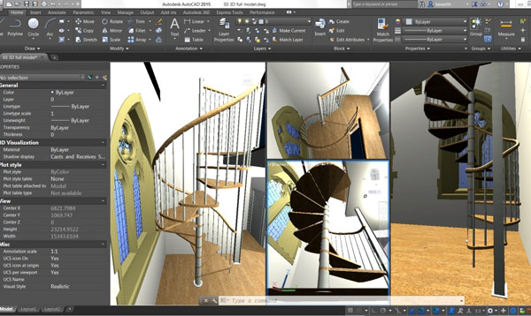
Cottage interior created in AutodeskAutoCad
Users without specialized education are unlikely to be able to figure it out right away; even numerous lessons presented in text and video versions will not be of serious help.
Compass
A program in Russian, which was created for creating drawings and three-dimensional models. It includes several main areas:
- mechanical engineering;
- construction;
- instrument making.
Read also
Site planning program
The “Construction” block is suitable for solving everyday problems, creating models and drawings of the future home.  The advantage of the program is that it automatically makes cuts and sections of the created model, eliminating possible designer errors. Can be used to prepare a complete set of project documentation.
Compass-construction includes all necessary set applications for turnkey building design. Starting from the creation of a 3D model, with detailed elaboration appearance, facade and other things, and ending with all utilities: water supply, sewerage, electrical networks, heating and so on.
T-Flex Cad
The program has a free version and is designed to work with both two-dimensional and three-dimensional images. It has wide capabilities and a comprehensive set of functions for drawing diagrams and . You can create either individual elements or an entire building with a section of all facades and floors. The T-Flex Cad developers focused on automating all processes. Design is carried out quickly, accurately and with a minimum amount of possible errors. Creating parametric models is the best use for the program.
Using this utility, you can both develop all the necessary documentation for the construction of a private house, and use it to develop unique pieces of furniture for the future interior.
T-Flex Cad provides full support ESKD and foreign standards.

Creating an apartment layout in the T-Flex Cad program
Model elements are interconnected by parametric and geometric relationships. The benefits of the program include:
- Powerful geometric core;
- Ease of working with assemblies of any complexity;
- Unified file format;
- Advanced engineering analysis tools;
- Ability to create your own element libraries;
- Teamwork on projects;
- Integration;
- Automation;
- Preparation of drawings in accordance with standards.
These features of T-Flex Cad turn it into a worthy competitor, but much simpler and more understandable.
They are similar in all programs, but it will take time to master and get used to each specific program. Therefore, try to choose the program that suits you best, master it and then work only in it.
The three leading programs in this area are CATIA v5, ProEngineer and Unigraphics. These programs have very broad 3D modeling and drawing capabilities, but they require a high-performance computer to run. These programs are focused on creating three-dimensional and subsequently creating based on these models. The following programs are simpler and less demanding in terms of performance: AutoCAD, Solidworks and Compass. Most commonly used for simple drawings AutoCAD program.
To create a drawing, open the selected program and create new drawing. Next, having chosen the drawing format, proceed to drawing. All programs have a toolbar with simple operators (point, line, circle). Using these operators, the basic geometry is constructed. There is also a toolbar with advanced operators (crop, ). After construction using the panel, mark the dimensions on the drawing. Subsequently, the drawing is printed.
Sources:
- computer drawing programs
The main problem that the system solves KOMPAS-3D, is product modeling. In this case, two goals are pursued at once, namely a significant reduction in the design period and the speedy launch of models into production.
Instructions
Sometimes there is a need to open something that was previously created using another program. For example, consider the transfer option drawing and from AutoCAD. How can such an operation be performed? Let's look at all the necessary steps one by one.
In fact, there is nothing complicated here. Those drawing and, which are designed in AutoCAD, as a rule, have the AutoCAD DWG or AutoCAD DXF format. And in order to open them in Compass, activate the following options: File->Open->Type AutoCAD files DXF/AutoCAD DWG, and specify in the desired folder file name.
Sometimes it is not necessary to specify exactly the file types listed above. You can select the “All files” option and find the one you need drawing in the folder yourself.
There is another option. Right click mouse click on the required file, then in the context menu select the following options exactly in the order in which they are given: Open with->Select program->Compass-3D LT. In this case, the program will do everything for you, that is, it will automatically translate the necessary drawing into the appropriate format. That's basically it. Now you can work in peace.
A little retreat. If drawing there is too much for her, and the files in the folder are presented in different formats, then it is best to use either the first or the last option.
note
The objectives of the KOMPAS-3D system are achieved thanks to the following capabilities:
Transferring model geometry to calculation packages;
- fast receipt technological and design documentation, which is necessary for the production of products. These include assembly drawings, specifications, details and much more.
- transfer of geometry to control software packages for CNC equipment;
- creation of additional images of the product model, for example, for compiling relevant catalogs.
Sources:
- how to draw in a compass
Design work is unthinkable without drawings. They can be drawn by hand, which takes quite a lot of time. This work can be greatly facilitated by using specialized computer programs.

Instructions
While creating drawings can be used different programs, the specific choice depends on what field you are working in and what kind of drawing you need. One of the most famous programs for computer aided design is CAD AutoCAD. This program allows you to create projects of any complexity and print finished drawings. It suits the vast majority design work, its latest versions support 3D modeling.
Despite all the advantages of AutoCAD, in some cases the designer needs more specialized programs. For example, if you want to create a drawing of a yacht, you should look for programs created specifically for this purpose. They will help you easily and quickly prepare the necessary drawings, with their help you can calculate specific shipbuilding tasks - for example, the stability of the future vessel, its draft and trim.
To design yachts you can use the following specialized programs: AutoShip, Rhinoceros, AutoYacht, CATIA, Freeship, CARENE. All these programs can be found on the Internet. They are best suited for amateur designers, as they are quite easy to learn and allow you to quickly calculate various options designs and create working drawings. Can be used very good program 3D modeling COMPASS, actively used in the most different areas design activities.
The SolidWorks automated design system has remarkable qualities. It allows you to work with the most complex projects, while the designer gets the opportunity to create solid 3D models of parts and assemblies of the structure being developed. It is very pleasant to work in this program; a working drawing can be easily created from a finished three-dimensional part. The advantage of the program is that when the layout of components or dimensions of parts changes, the remaining dimensions are automatically adjusted to fit new option, which saves the designer from a lot of tedious work. SolidWorks, along with AutoCAD, is the market leader automatic systems design.

3D modeling programs can help turn some ideas into beautiful models and prototypes that can later be used in the most for different purposes. These tools allow you to create models from scratch, regardless of skill level. Some 3D editors are quite simple, so they short time even a beginner can master it. Today, 3D models are used in the most various fields: this movie, computer games, interior design, architecture and much more.
Choosing the optimal software for modeling is often difficult, since it is not easy to find a program that would have all the necessary functionality. FreelanceToday brings to your attention 20 free programs for 3D modeling.
Daz Studio is a powerful yet completely free 3D modeling software. This is not to say that this is an easy tool to learn; beginners will have to spend a long time studying the program’s capabilities. The creators of the program took care of user experience, but the convenience of Daz Studio will not be appreciated immediately. One of the features of the program is the creation of GPU-accelerated 3D images during rendering, which makes it possible to create very realistic models. Daz Studio also has support for creating scenes and functionality for animating models.
AvailableFor: Windows | OS X
Free 3D modeling software Open SCAD is designed for serious design (industrial design, interiors, architecture). The creators of the program were much less interested in the artistic aspects. Unlike other similar programs, Open SCAD is not an interactive tool - it is a 3D compiler that displays project details in three dimensions.
Available for: Windows | OS X | Linux
AutoDesk 123D is big set various tools for CAD and 3D modeling. Using the program, you can design, create and visualize almost any 3D model. AutoDesk also supports 3D printing technology. The main AutoDesk 123D site has several satellite sites where you can find a lot of interesting free 3D models that you can experiment with or just use for your own purposes.
Available for: Windows | OS X | iOS |
Meshmixer 3.0 allows you to design and visualize 3D structures by combining two or more models in just a few simple steps. There is a program for this convenient function“cut and paste”, that is, you can cut out the necessary parts from the model and paste them into another model. The program even supports sculpting - the user can create a virtual sculpture, shaping and refining the surface in the same way as if he were sculpting a model from clay. And all this in real time! The program supports 3D printing, finished models are fully optimized for sending to the printer.
AvailableFor: Windows | OS X
3DReshaper is affordable and easy to use 3D modeling software. The program can be used in various fields such as art, mining, civil engineering or shipbuilding. 3DReshaper comes with support for various scenarios and textures and has many useful tools and features to make the 3D modeling process easier.
AvailableFor: Windows
The free 3D Crafter program is designed for real-time 3D modeling and animation creation. The main feature of this editor is its intuitive drag-and-drop approach. Complex models can be built using simple shapes, the program supports sculpting and 3D printing. This is one of the most convenient tools for creating animation.
AvailableFor: Windows
PTC Creo is complex system, created specifically for engineers working in the field of mechanical engineering, as well as for designers and technologists. The program will also be useful for designers who create products using methods computer-aided design. Direct modeling allows you to create designs from existing drawings or use the program to visualize new ideas. Changes to the geometry of an object can be made very quickly, which significantly speeds up the work process. The program, unlike the previous ones, is paid, but there is a 30-day trial and a free version for teachers and students.
AvailableFor: Windows
Free software LeoCAD is a computer-aided design system virtual models LEGO. There are versions for Windows, Mac OS and Linux. The program can be a good alternative to Lego Digital Designer (LDD), as it has a simple interface, supports keyframes and works in animation mode. It is the support for animation that sets LeoCAD apart from other programs of a similar nature.
AvailableFor: Windows | OS X | Linux
The VUE Pioneer program will help you create a three-dimensional model for visualizing the landscape. The software may be useful for advanced users who are looking for convenient rendering tools. Pioneer lets you create amazing 3D landscapes with large quantity presets and provides direct access to Cornucopia 3D content. Using the program you can create many lighting effects.
AvailableFor: Windows | OS X
Netfabb is not only a program for viewing interactive 3D scenes, it can be used to analyze, edit and modify 3D models. The program supports 3D printing and is the easiest and simple tool in terms of installation and use.
AvailableFor: Windows | OS X | Linux
The free NaroCad program is a complete and extensible computer-aided design system based on OpenCascade technology and runs on Windows platforms and Linux. The program has all the necessary functionality and supports basic and advanced 3D modeling operations. The program's functions can be expanded using plugins and a software interface.
AvailableFor: Windows | Linux
LEGO Digital Designer allows you to build 3D models using virtual LEGO bricks. The result can be exported to various formats and continue working in other 3D editors.
AvailableFor: Windows | OS X
The free ZCAD program can be used to create 2D and 3D drawings. Editor supports various platforms and provides large viewing angles. The presence of many convenient tools allows you to solve most problems associated with modeling three-dimensional objects. The program's user interface is simple and intuitive, which greatly facilitates the drawing process. The finished project can be saved in AutoCAD format and other popular 3D formats.
AvailableFor: Windows | Linux
The free version of Houdini FX, Houdini Apprentice, is useful for students, artists, and hobbyists creating non-commercial 3D model projects. The program has a somewhat stripped down, but at the same time quite broad functionality and carefully thought out user interface. To the disadvantages free version This may include a watermark that is displayed on the 3D visualization.
AvailableFor: Windows | OS X | Linux
The design worksheet app allows you to create fairly detailed 3D models. The creators of the program took care of functions that allow you to eliminate problem areas through changes and additions to existing design. DesignSpark can also be used to quickly change the concept of a 3D product. The program supports direct modeling techniques and 3D printing of models.
AvailableFor: Windows
FreeCAD is a parametric 3D modeler designed to create real objects of any size. The user can easily change the design by using the model history and changing individual parameters. The program is multi-platform and can read and write various file formats. FreeCAD allows you to create your own modules and then use them in further work.
AvailableFor: Windows | OS X | Linux
The free Sculptris program will open a window to the exciting world of 3D for users. Features of Sculptris are convenient navigation and ease of use. The program can be easily mastered even by a beginner who has no experience in digital art or 3D modeling. The work process is designed in such a way that you can forget about geometry and simply create a model, while carefully using computer resources.
Available for: Windows | Linux
MeshMagic can be used to render 3D files as well as create two-dimensional objects or converting them to 3D. The software is intuitive clear interface and can be used to solve the most different tasks. Mesh Magic currently only supports Windows. The result is saved in the popular STL format, which can be opened and edited in most online and offline 3D modeling tools.
AvailableFor: Windows
Open Cascade is a software development kit designed for creating 3D CAD related applications. It includes custom, community-developed C++ class libraries that can be used for modeling, visualizing and communicating data, and for rapid application development.
AvailableFor: Windows | OS X | Linux


