CAD programs: overview for different platforms. Computer-aided design system (CAD). who will win
Question No. 1. Review of modern computer-aided design (CAD) systems
Computer-aided design system - an automated system that implements information technology for performing design functions, is an organizational and technical system designed to automate the design process, consisting of personnel and a set of technical, software and other means of automating its activities. The abbreviation CAD is also widely used to denote such systems.
Creation goals and objectives
As part of the life cycle of industrial products, CAD solves problems of automation of work at the stages of design and pre-production.
The main goal of creating CAD is to increase the efficiency of engineers, including:
reducing the complexity of design and planning;
reduction of design time;
reducing design and manufacturing costs, reducing operating costs;
improving the quality and technical and economic level of design results;
reducing costs for full-scale modeling and testing.
Achieving these goals is ensured by:
automation of documentation;
information support and automation of the decision-making process;
use of parallel design technologies;
unification of design solutions and design processes;
reuse of design solutions, data and developments;
strategic design;
replacing full-scale testing and prototyping with mathematical modeling;
improving the quality of design management;
application of variant design and optimization methods.
CAD Review
Traditionally, CAD products for mechanical engineering are divided into three classes: heavy, medium and light. This classification has developed historically, and although there has long been talk that the lines between classes are about to be erased, they remain, since the systems still differ in both price and functionality.
As a result, there are now several powerful systems in this area, the kind of “oligarchs” of the CAD world, steadily developing middle-class products and received mass distribution inexpensive “light” programs. There is also a so-called “non-class stratum of society”, the role of which is played by various specialized solutions.
CAD classes. Heavy CAD
Computer technology is not intended to automate traditionally existing technological links (since this usually does not give any effect, with the exception of some changes in working conditions), but to fundamentally change the very technology of design and production of products. Only in this case can we expect a significant reduction in the time required to create products, reduce costs over the entire life cycle of the product, and improve the quality of products.
First of all, in relation to the creation of complex mechanical engineering products, the basis of the organization computer technology lies in the creation of a complete electronic model of the product, since it is the creation of three-dimensional electronic models, adequate to the actually designed product, opens up enormous opportunities for creating higher quality products (especially complex, high-tech products) and in a shorter time.
Ideally, in the process of designing and manufacturing complex and multi-component products, everyone involved in the design should, working simultaneously and observing each other’s work, immediately create electronic models of parts, assemblies, assemblies, systems and the entire product on computers.
At the same time, it is necessary to simultaneously solve problems of conceptual design, all kinds of engineering analysis, modeling situations, as well as product layout and the formation of external contours. Without waiting for the development of a new product to be completely completed, this information should be used for technological preparation of production and production as such. In addition, it is necessary to automatically manage all the created data of the electronic model (that is, the structure of the product), and the process of creating the product itself, and also be able to manage the structure of the process of creating the product.
To implement computer technology for design and production, computer-aided design, engineering analysis and technological preparation systems (CAD/CAE/CAM) must be used. top level, as well as project management systems (PDM - Product Data Management).
Middle class CAD
In the world of CAD middle class arose later than the other two - in the early 90s. Previously, only expensive heavy systems had 3D solid modeling tools, and lightweight programs were used for 2D drawing. Medium CAD systems have taken an intermediate position between the heavy and light classes, inheriting from the former three-dimensional parametric capabilities, and from the latter - low price and focus on Windows platform. They revolutionized the world of CAD, paving the way for small design organizations to move from 2D to 3D design. An important role in the development of the middle class was played by two solid-state parametric modeling kernels ACIS and Parasolid, which appeared in the early 90s and are now used in many leading CAD systems. The geometric kernel serves to accurately mathematically represent the three-dimensional shape of a product and control this model. The geometric data obtained with its help are used by CAD, CAM and CAE systems for development structural elements, assemblies and products. Currently, Parasolid is owned by EDS, and ACIS is owned by Dassault, which sell licenses for their use to anyone. There are many such people - these kernels form the basis of more than a hundred CAD systems, and the number of licenses sold has exceeded a million. Success is clear - after all, the use finished kernel relieves system developers from solving time-consuming solid modeling tasks and allows them to focus on user interface and other functions. However, this does not mean that all middle-class CAD systems are built on the basis of these mechanisms. Many companies value independence and prefer to develop their own engines.
Analysts consider systems costing about 5-6 thousand dollars per workplace (prices in the USA) to be in the middle class. For comparison: for heavy CAD systems, a workplace costs about 20 thousand dollars, but Lately suppliers have released lighter versions of products that cost less.
According to the forecast of the analytical company Daratech, the growth of the middle class will continue, and it is expected that until 2008 the market will increase by 11% per year. The reason for such positive dynamics is the active influx of new users from both adjacent camps - heavy and light systems. Thus, according to analysts, there are now more and more manufacturers who are dissatisfied with the poor return on their investments in expensive products and are looking for cheaper options. On the other hand, globalization, increasing competition and the downturn in the global economy are forcing small and medium-sized enterprises to switch from 2D to 3D CAD to speed up the launch of new products and improve their quality. The transition is being driven by improved compatibility between 2D and 3D systems and increased productivity benefits of mid-range CAD software. Medium-sized CAD systems now have a wide range of potential consumers, and they, willingly or under market pressure, will be forced to implement them sooner or later. The expansion of the functionality of these products also plays into the hands of the “middle peasants”. As a result, enterprises that want a reliable 3D modeling tool, but can do without highly developed heavy CAD tools, now have additional options for selecting software. After all, suppliers previously claimed that the average CAD systems have 80% of the functions of heavy products, and their price is only 20% of the cost expensive systems. Now, according to analysts from Daratech, the “middle peasants” are approaching 90% in terms of capabilities and 50% in terms of cost.
Of course, even this 10% gap cannot be discounted. For example, enterprises in the automotive and aerospace industries are in dire need of advanced functionality found only in “heavyweights.” Therefore, the distinction between these two classes exists and will remain for the foreseeable future, since the developers of both systems are not sitting idly by, but will continue to improve your products.
SolidWorks has become a pioneer in the field of medium-sized CAD systems. In 1993, it introduced a product of the same name, which had a three-dimensional geometric core, which, according to the creators, was close in capabilities to solid-state modeling mechanisms for heavy systems, but was much cheaper. Soon the example of the pioneer was followed by Solid Edge, which released the CAD software of the same name, and then by Autodesk. She first developed the 3D Mechanical Desktop program based on 2D AutoCAD, and then created the new Inventor software. In addition to these systems, there are many other middle-class CAD systems on the market, for example think3, Cadkey, Alibre. There are also Russian developments among them. Thus, the ASCON company promotes the KOMPAS system based on its own geometric kernel, and the Top Systems company promotes the T-Flex program based on the Parasolid kernel owned by UGS. They have also gone through a long development path and acquired built-in tools for surface modeling, document management (PDM), technological preparation of production (CAM), etc., but at the same time they are significantly cheaper than their foreign counterparts and are initially focused on domestic standards and design techniques.
Lightweight CAD
Programs in this category are used for two-dimensional drawing, so they are usually called an electronic drawing board. To date, they have added some 3D capabilities, but do not have the parametric modeling tools that heavy and medium CAD systems have.
The first drawing system, Sketchpad, was created back in the early 60s, and then many other products of this kind appeared, using advances computer graphics. However, the real flourishing in this area came only in the 80s with the advent of personal computers. Following the decline in equipment costs, there was a collapse in prices for CAD systems.
The pioneer in this area was Autodesk, which in 1983 released a CAD system for PC called AutoCAD. The success was phenomenal - already in 1987, 100 thousand copies of AutoCAD were sold, and today this number exceeds four million. As a result, Autodesk was able to grab a fair share of the CAD market, displacing heavyweights from the 2D drawing software segment. The other players followed the example of the pioneer. So, in 1984, Bently introduced the Microstation program, which became the main competitor to AutoCAD. In addition to them, there are now many other “light” CAD systems, including DataCAD of the same company, TurboCAD from IMSI, SurfCAM from Surfware and others. These products are simpler and cheaper ($100 - $4,000) than heavy and medium-sized CAD systems, so they are in demand, despite the current economic downturn. As a result, “light” systems have become the most common design automation product, a kind of " workhorse"of the CAD world.
In addition to heavy, medium and light CAD systems, there are specialized CAD systems, industrial design, construction design (reinforced concrete), and architectural design.
According to the unanimous opinion of analysts, the global CAD market has reached maturity. It developed and grew rapidly during the last decade of the last century. But by 2000, all the businesses that needed CAD software had acquired them, and it became difficult to find new users. And when the economic recession began in the West, the growth of the CAD market slowed down: according to the analytical company Daratech, in 1999, sales of CAD/CAM/CAE systems grew by 11.1% over the year, in 2000 - by 4.7% , in 2001 - by 3.5%, and in 2002 - by 1.3%. At the same time, the growth in turnover of leading CAD suppliers also stopped. Daratech estimates that in 2002 the CAD market was worth $6.2 billion (user spending on software and services); in 2003, sales decreased by 4.5%.
So, at the turn of the century, a turning point came for the CAD market. In such a situation, companies usually merge and search for new directions for growth. An example is the purchase by EDS in 2001 of two well-known developers of heavy CAD systems - Unigraphics and SDRC. This deal created a real sensation in the CAD segment. However, now the success of the purchase is in doubt, since EDS is going to sell the UGS PLM division, formed by the merger of Unigraphics and SDRC. As for the search for new directions, leading suppliers are now actively promoting the concept of PLM (Product Lifecycle Management), which implies managing information about a product throughout its entire life cycle. The implementation of PLM promises many benefits for enterprises, but entails costs for the purchase of additional software (for example, engineering data management systems - PDM) and the reorganization of project processes.
Thus, the development of the CAD market follows two paths - evolutionary and revolutionary. At one time, the first CAD systems for PCs and middle-class systems produced a revolutionary revolution. Now the market is developing evolutionarily: the functionality of products is expanding, productivity is improving, and ease of use. But perhaps another revolution awaits us soon. Analysts at Cambashi believe this will happen when CAD vendors begin to use standard SQL-type databases to store engineering data (drawings, 3D models, bill of materials, etc.) instead of file structures. As a result, engineering information will become structured, and it will be much easier to manage than it is now.
GOSTs of the Union of Soviet Socialist Republics provided for the division of CAD into nine groups:
8) reserve;
9) reserve.
In fact, such a classification meant dividing systems “by purpose.” However, universal CAD systems are successfully used in various subject areas; in addition, the list does not contain, for example, “geodetic” systems, which, according to some data, today account for about 13% of the market for all CAD systems sold in the world.
CAD is also divided according to the complexity of the design object:
Up to 100 components - simple objects;
From 100 to 1000 - objects of medium complexity;
From 1000 to 10000 - complex;
From 10,000 to 1,000,000 - very complex;
Over 1,000,000 objects of very high complexity.
For lovers of the Russian language, we can offer a small logical exercise: try to “feel the difference” between CAD very complex objects and CAD objects of very high complexity.
If the design object is a certain product, then the part is an integral part of the object. If a certain technological process, That What is an integral part of CAD, no one has yet determined...
CAD systems also differ in their level of automation:
Low-automated CAD systems (up to 25% of design procedures);
Moderately automated (from 25% to 50% of project procedures);
Highly automated (over 50%)
About 6-8 years ago, all machine-building enterprises had to periodically send reports on the level of automation to their ministries in Moscow.
There are several more signs of CAD classification that are determined by GOST, such as “number of issued documents,” but we will not consider them.
“Bourgeois” CAD/CAM/CAE systems are classified much more simply: full-scale, fully functional CAD/CAM/CAE systems on workstations are called “heavy” CAD systems, and all others are called “light” CAD systems.
All of the above CAD/CAM/CAE systems are “heavy”, while AUTOCAD and PEPS are “light”. In Russia, “heavy” CAD systems in the full sense of the word have not yet been developed. It should be noted that in the West, in terms of CAD classification, there is also no stable terminology. Some experts classify, for example, CIMATRON as “average” systems in terms of price per workstation. The price of CIMATRON is, indeed, significantly less than the price of, say, CADDS5, and the requirements of the Israeli system for computer computing resources are more modest. In some publications, “heavy” is called CAD, 1 copy of the software costs more than $15,000.
In the last 2-3 years, a significant share of sales in the CAD market began to be made up of so-called “middle” class systems operating on the WINDOWS 95/NT platform. Almost all manufacturers of CAD/CAM/CAE systems have released truncated versions of their “heavy” CAD systems for personal computers. Examples include, in particular, the PT/Product systems from PTC and the Prelude systems from MATRA DATAVISION. A large range of new “medium” CAD systems has been produced by a number of American companies: Solid Works97 (Solid Works Corp.), Solid Edge (Intergraph Corp.), Microstation 95 (Bentley Systems), Autodesk Mechanical Desktop (Autodesk Ltd.).
Let's try now to solve one problem. Let's imagine that we have to make a decision to purchase a foreign CAD/CAM/CAE system for our enterprise. What should we choose? Naturally, no company will provide us with an objective comparative analysis of systems. Dealers and distributors of all stripes praise, of course, only their systems. The same CIMATRON, for example, says that in terms of sales dynamics it ranks 1st in the world. The indicator, of course, is good, but a system with which, say, 2 enterprises were bought last year, and 10 this year, will have a sales increase of 500%, but this does not mean that the system with the worst indicator is worse. In computer magazines, comparative analysis of CAD/CAM/CAE systems can also suffer from subjectivity, because many articles are written with specific goals. Let us, however, try to express some thoughts on this matter.
First of all, it should be noted that a big misconception of many managers is the opinion that in the West all enterprises work with “heavy” CAD systems. The greatest effect from the implementation of CAD/CAM/CAE systems was obtained in the aircraft industry, automotive industry, shipbuilding, etc., i.e. in the production of complex and expensive products. Therefore, if our company designs and manufactures bolts and nuts, then perhaps we should limit ourselves to purchasing “medium” or “light” CAD systems, and perhaps we should also think about purchasing a domestic design. But more on that later.
Still, CAD/CAM/CAE systems are bought in the West, “so someone needs it.” A good indicator of the quality of the system “they have” is the sales volume indicator. Let us cite, for example, data for 1994.
1. CV - $227 million - 17% of the amount of all contracts for the supply of CAD/CAM/CAE systems.
(According to some analysts, in 1995-1996, RTS took first place in terms of sales volume).
As you can see, there is little left for the rest. In any case, DELCAM and CIMATRON are not even in the top ten. Here, however, personal computer systems were not taken into account.
Now about the technical specifications.
From reliable sources, we can conclude that the CAD subsystem is best implemented in the CATIA system. We are talking specifically about modeling objects, and not about assembling products and designing drawings.
The CAM subsystem (meaning CNC tasks) is preferable to UNIGRAPHICS and Pro/Engineer. Pro/Engineer also has the most organic functions for product parameterization in the CAD subsystem.
The most complete CAE subsystem is in the French CATIA and EUCLID systems.
The best information management subsystem and the greatest “integration” is found in the world leader N 1, the CADDS5 system.
The best performance/price indicator is that of CIMATRON. He, apparently, due to the well-known demographic “proximity,” has the best documentation in Russian.
This analysis can be continued, but I think it’s not worth it. The main thing to remember is that when choosing a system you need to think analytically and, again, understand dialectics. It seems obvious that if we need a system for designing control programs for a 5-axis milling machine, then we should look for a CAM system - the best system for this indicator. However, this does not always need to be done. For example, a bad post-processor can ruin everything.
Let us now move on to consider domestic developments. As we have already noted, national systems operate mainly “on the platform” of MS DOS. MS WINDOWS versions systems are, most often, adaptation to a new OS of only the “head” part of the system, while the kernel remains unchanged.
Among the most common developments, with at least several hundred installations in various industries, we should mention the “KOMPAS” systems of JSC “ASCON” (St. Petersburg) and “SPRUT” of JSC “SPRUT-Technologies” (Naberezhnye Chelny). Recently, the “Moscow-Izhevsk” ADEM system has begun to be sold in the Ural region. Its distributor is the Yekaterinburg representative office of the company BEE PITRON, the same one that sells the CAD/CAM/CAE system CIMATRON.
What are the features of domestic CAD/CAM/CAE systems?
First of all, it is worth noting the history of the creation of these and other CAD systems. It is characterized by two main points:
1) the desire to create a “native” CAD system, an alternative to the “foreign” AUTOCAD;
2) an attempt to integrate domestic means of automating the preparation of control programs for CNC machines, long used at machine-building enterprises, into a new graphical environment resulting from the development of a new CAD system.
That is why the developers of CAD subsystems for the KOMPAS and ADEM systems simply used technological modules from other developers when developing the CAM part. So, for example, “Moscow” graphics editor CherryCAD of the ADEM system was supplemented with the old “Izhevsk” KATRAN system. And the graphic editor KOMPAS-GRAPHIC of the KOMPAS system is used as a means of describing the geometry of parts for various technological subsystems, collected, it seems, from all over the country. Among them is the well-known in Russia automation system for programming volumetric processing for CNC milling machines GEMMA-3D. This system was originally developed at a Moscow research institute specializing in helicopter design. The KOMPAS system also has a native CNC module called KOMPAS-CNC, but the developers themselves recommend it only for processing parts of simple shapes. Even the CAD subsystem, with which KOMPAS began, and which is now developing in the direction of applications related not to modeling, but to the automation of the preparation of design documentation (KOMPAS-KD subsystems, SPECIFICATIONS, etc.), is usually supplemented by a “non-native” three-dimensional system solid modeling KITEZH.
As for the SAE subsystems, KOMPAS has a number of software packages for design calculations, for example, the subsystem of strength calculations using the ZENIT finite element method. We do not have reliable information about the developers of ZENIT, but we are convinced that they also had nothing to do with the development of KOMPAS and are simply selling their system through ASCON JSC.
This trend is generally characteristic of all integrated domestic CAD systems. As a rule, they are a “hodgepodge” of various subsystems, written by different developers at different times, interconnected by a hastily created interface (usually a file interface).
The approach to creating integrated “end-to-end” CAD systems is somewhat different for the developers of the SPRUT system. They do not offer a ready-made CAD/CAM system, but a set of tools (including specialized languages) for developing your own design and technological CAD systems. They also supply ready-made workstations (Automated Workstations) for a CNC program developer or a software package for engineering calculations of cold sheet metal stamping, but they prefer that you develop your system yourself. This approach assumes in advance that the programming level of system users is quite high, however, this is not always the case, especially in small enterprises.
Summarizing this short review, we can say that domestic CAD systems belong to the class of “light” or “medium” CAD/CAM/CAE systems and are inferior to their Western counterparts in terms of capabilities and complexity of solving design and technological problems, despite the fact that individual elements Design automation in domestic subsystems is better implemented. An example is the system of geometric three-dimensional modeling GM+, developed at one time by a teacher of the Department of “Applied Geometry and Design Automation” of USTU E.I. Kats with the participation of a group of other teachers of the department under the guidance of prof. R.A. Vaisburd. Many modeling issues are solved in it much more effectively than in EUCLID-e or CIMATRON-e. At the same time, the system has still not been truly implemented anywhere. Attempts to “insert” it into Western commercial versions of 3D CAD systems, as far as we know, did not lead to anything. There are many reasons here, and the most important, in our opinion, is that the West does not want to buy our CAD developments and always finds many “objective” reasons to explain the impossibility of using a Russian software product in Western CAD/CAM/CAE systems. Of course, problems with “Russian software” actually exist. Here there is the uncertainty of the legal relationship between the developer and the Western dealer, and communication problems, and, finally, the well-founded doubt of Western partners about the ability of Russian developers to fulfill their contractual obligations if any errors are discovered in the programs.
Perhaps less significant is the reason that many of our developers naively consider to be the main one. We are talking about a discrepancy between the design of user documentation and design results and international standards. There is an illusion that by ensuring that the programs comply with Western “GOST” standards and by translating the “User Guide” into English, and then inserting it into a colored cardboard “box”, like all “decent” Western systems, we can achieve great success in selling our developments in the Western market. This is wrong. The pride of the developers of the ADEM system (Omega Technologies Ltd, Moscow) for the fact that they managed to create, as they say, “the only CAD software product in Russia that meets international standards” is quite understandable, but their stories about how well and effectively their CAD/CAM system is used in American or Canadian enterprises contains a lot of deceit. The scenario for all sales of Russian CAD systems to the West is exactly the same ( we're talking about not only about the ADEM system, but also, for example, about the T-FLEX CAD CAD system) and is as follows. One of the developers or people associated with the developers leaves, say, for the USA, “for permanent residence” and gets a job in a certain company. As a specialist in the field of programming and CAD, he is involved in automating the solution of any design tasks. He persuades the company's management to use a familiar software product for these purposes. This is how a company using Russian CAD appears in the USA. As soon as our Russian specialist or group of specialists stops working for this company, the victorious march of Russian developments across the “North American states” stops. It would never occur to any Western company to “just like that” prefer, for example, ADEM to AUTOCAD. And we can firmly say that this “status quo” will not change radically in the near future.
At the conclusion of this subsection, a few more words about the choice of CAD.
At the majority of Russian machine-building enterprises, at the stage of technical preparation of production, real modeling of new objects does not occur. The task of designers and technologists is, as a rule, to link an existing project, developed by some institute, to the technological features of their enterprise. Therefore, the main part of design solutions consists of working drawings necessary for the manufacture of individual parts, assembly drawings, various kinds of design specifications, route and operational flow charts, etc. Automation tools for drawing work with this approach to production preparation are usually a simple two-dimensional graphic editor like AUTOCAD, and text design and technological documents are prepared even without the use of graphic tools using specialized systems such as those developed, for example, by the Regional Engineering Center “ISET” at USTU. They are some specialized DBMSs written in languages like FoxPro.
For the production of ordinary engineering parts on CNC machines, 2- and 2.5-axis machining is also sufficient. Three-dimensional processing is necessary mainly for the production of various molds. That is why foreign CAD/CAM systems are purchased by large enterprises, mainly for the departments of the Chief Technologist, and the CAD subsystem is used in this case only to describe the geometry of a three-dimensional object for the purpose of its subsequent production on a CNC machine. In this case, there is no need to talk about any “end-to-end” CAD.
For operating rooms Windows systems exists great amount CAD programs, and in Linux you can count them on your fingers, but there are still decent options.
Computer-aided design (CAD) is an integral part of many engineering streams. CAD is used professionally in architecture, auto parts, space shuttle research, aeronautics, bridge construction, interior design, and even clothing and jewelry.
Some professional CAD programs, such as SolidWorks and Autodesk AutoCAD, are not supported on the Linux platform. Therefore, today we will look at the TOP CAD that are available for Linux.
Best CAD Software Available for Linux
Before you see the list of CAD software for Linux, you should remember that not all applications listed here are open source.
This article provides instructions for installing software for Linux distributions on Ubuntu based. You can check the respective websites to know the installation procedure for other distributions.
The list is not competitive. Application number one should not be considered better than number three, etc.

FreeCAD is a great option for 3D modeling that is free and open source. FreeCAD is built with mechanical engineering and product design as the end goal. FreeCAD is multi-platform and available for Windows, Mac OS X and Linux.

Although FreeCAD was the choice of many Linux users, it should be noted that FreeCAD is still at version 0.17 and therefore not suitable for large deployments. But recently development has accelerated.
FreeCAD does not focus on direct 2D drawings and animation of organic shapes, but is great for design related to mechanical engineering. FreeCAD version 0.15 is available in the Ubuntu repositories. You can install it by running the command below.
Sudo apt install freecad
To get the new daily builds (0.17 at the moment), open a terminal (ctrl+alt+t) and run the commands below.
Sudo add-apt-repository ppa:freecad-maintainers/freecad-daily sudo apt update sudo apt install freecad-daily
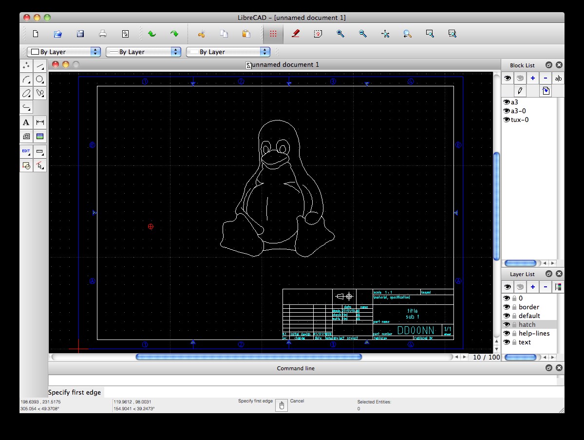
LibreCAD is free solution open source. Generally, CAD tends to be a resource-intensive task, and if you have fairly modest hardware, then I suggest you try LibreCAD as it is really lightweight in terms of resource usage. LibreCAD is an excellent candidate for geometric designs.

As a 2D tool, LibreCAD is good, but it can't handle 3D models and renderings. It can be unstable at times, but it has reliable autosave that won't let your work get lost.
You can install LibreCAD by running the following command
Sudo apt install librecad

OpenSCAD is free 3D CAD software. OpenSCAD is very lightweight and flexible. OpenSCAD is not interactive. You need to "code" the model, and OpenSCAD interprets that code to render the visual model. It's a compiler in a sense. You can't draw a model, but you can describe it.
OpenSCAD is the most complex tool on this list, but once you get to know it, it provides an enjoyable experience.
you can use following commands to install OpenSCAD.
Sudo apt-get install openscad

BRL-CAD is one of the oldest CAD tools. It has always been a favorite of Linux/UNIX users because it aligns with the philosophies of modularity and freedom.
BRL-CAD was launched in 1979 and is actively developing. Now BRL-CAD is not AutoCAD, but it is still excellent choice for transport studies such as thermal and ballistic penetration. BRL-CAD underlies CSG instead of boundary representation. You might want to keep this in mind when choosing BRL-CAD. You can download BRL-CAD from the official website.
5. DraftSight (not open source)
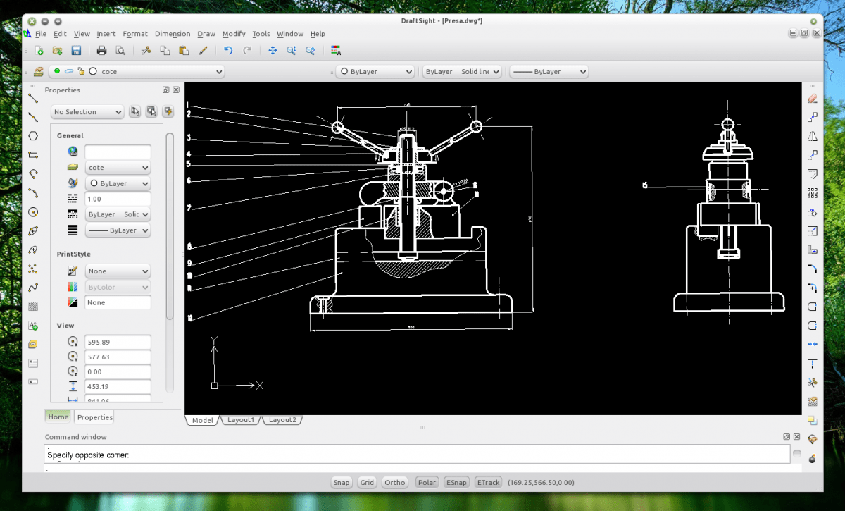
If you are used to working in AutoCAD, then DraftSight is a great alternative for you.
DraftSight great tool CAD available on Linux. It has a fairly similar workflow to AutoCAD, making migration easier. It even provides a similar appearance. DrafSight is also compatible with the AutoCAD .dwg file format. But DrafSight is 2D CAD software. It does not currently support 3D CAD.
Although DrafSight is commercial software with a starting price of $149. Free version also available on the DraftSight website. You can download the .deb package and install it on Ubuntu based distributions. You need to register your free copy using your ID Email to start using DraftSight.
You might find it useful
With the huge growth in cloud computing technology, cloud CAD solutions like OnShape are becoming more popular every day.

The global CAD (design automation software) market is constantly evolving. Modern software packages allow you not only to quickly create detailed drawings, but also 3D models, as well as technical documentation to them. Such utilities are most often used in conjunction with automated analysis and calculation systems, called CAE.
CAD market in the world and the CIS
Sales of CAD software are increasing every year; at the moment, at least 6 million people use such software. The market began to develop especially actively after the global economic crisis of 2009. According to forecasts at the end of 2017, CAD sales should reach $8.7 billion.
The popularity of CAD depends on the region in which these solutions are implemented. Software is sold most dynamically in countries whose economies are on the rise. The ranking of the most popular manufacturers of design automation utilities is presented in Diagram 1.
Diagram 1. The largest CAD manufacturers according to JPR research in 2014
Unlike other software sectors, the CAD market is very open to new players taking advantage of opportunities and offering new technologies. Among the companies offering a large number of innovative solutions, GrabCAD, SpaceClaim and Hexagon should be mentioned.
In terms of geographical distribution, European countries occupy the first place in the market, which is due to the presence on the continent of enterprises operating in areas considered the main consumers of CAD products:
- Electronics and electrical engineering,
- Mechanical and aircraft engineering.
Development of the CAD market in countries former USSR it is difficult to analyze, since of all domestic manufacturers only ASCON provides open access to information about your income. However, we can say that in the CIS countries 2D design systems are gradually being replaced by 3D programs, which allow not only to create volumetric models and documentation for them, but also to manage the life cycle of a project or product composition.
Most enterprises in the post-Soviet space have abandoned unlicensed software, although the number of illegal users remains quite high. At the same time, in financial terms, the annual growth of the CAD market has been at least 20% over the past 10 years. These indicators are ensured by high world oil prices and great interest in automation of mining and processing enterprises. Enterprises working in the field of mechanical engineering are widely implementing software that allows automating work. The main CAD market in Russia today is controlled by 5 key companies.
 Due to the emergence in recent years of a large number of paid services in the field technical support, provided by the vendor, as well as the complication of utility functionality, it is planned that in the coming years the growth of the services market will be at least 5% faster than sales of new licenses.
Undoubtedly, due to the crisis, sales volumes of CAD products have decreased, especially when it comes to popular universal systems, however, brands offering software at a more expensive price category did not experience a significant reduction in sales.
Inventor Software Overview
This program is one of the oldest three-dimensional design systems. Its first versions appeared back in 1999, since then Autodesk has released at least a hundred updates, which has turned Inventor into a kind of standard in the domestic CAD market.
The main advantages of this software are:
- The presence of a parametric modeling function that allows you to set characteristics for each of the model elements;
- Flexibility, which refers to the ability to use different methods design with fairly low requirements for computer software;
- Ability to create models separately and include them in assemblies;
- A function that allows you to create 2D drawings for created 3D models.
Our subscriber and good friend Mikhail Azanov gave a good overview of the interface and capabilities of this program:
For those who want to quickly master the functionality of Inventor Autodesk, we can also recommend or download the free one. Or visit ours.
SolidWorks Software Overview
This program simultaneously uses two design principles - surface parametric and three-dimensional solid-state, which allows the designer to work on creating three-dimensional parts and compose assemblies of three-dimensional electronic models.
Using the program, you can see the future product with different sides and appreciate not only it specifications, but also the quality of design.
The principle of operation of the software has much in common with assembling a Lego constructor: the user assembles a model from template blocks that can be easily added and removed, as well as changed their characteristics. The resulting three-dimensional models, placed in three-dimensional virtual space, help to create the most accurate idea of the properties of the object and bring the computer model closer to the appearance of the future product without the need for prototyping.
A short review basic principles modeling in SolidWorks:
Overview of the KOMPAS 3D program
KOMPAS 3D is a unique software that allows you to implement ideas in 3D and create their documentation. At powerful functionality The program provides simplicity and convenience of operation. Reference system well known in countries of Eastern Europe, since it has an extensive database of standard parametric libraries, which contain a large number of template models that allow you to design parts of mechanisms, machines, architectural forms and parts. The developers offered a flexible, advanced toolkit that perfectly suits the goals of professionals who decide complex tasks on the construction of surfaces.
The program was created as a modular product that allows optimizing budget costs and reducing the time for implementing design and architectural plans. The user has the opportunity to create technological and design documentation in the form text documents And spreadsheets. In addition, the program is capable of creating instructions for production robots, which sets it apart from its competitors.
Overview of the KOMPAS 3D interface from Vertex Studio:
You can get an idea of the rules for working with software on our website in the section.
The best CAD in the CIS
Which software best suits the interests of domestic designers? KOMPAS 3D is receiving more and more positive reviews, the main advantages of which are:
- Relatively low cost;
- New program blocks;
- Modernized user interface;
- Systematic software update;
- Powerful design module for a variety of specifications.
The cost of a KOMPAS 3D license ranges from 1,490 to 200,000 rubles, depending on the type of universal automated system and the area in which it is planned to be used; the buyer can choose electronic or boxed version. You can purchase a license, for example, here: http://store.ascon.ru/.
You can find out the exact cost of SolidWorks products only by contacting the developers (request form - http://www.solidworks.ru/buy-solidworks/), but according to rumors it is at least 350,000 rubles, the price of Inventor is just as high.
So, the popularity of KOMPAS 3D is easy to explain: the software is affordable, the rules for working with it are easy to learn, and the rich collection of templates will satisfy the needs of even a large design center.
What do you think about KOMPAS 3D? Write in the comments.
By the way, we have finished work on creating a new bestseller - !

The idea was born in my head from our poverty of our needs. For those who have decided to master some kind of CAD, it would seem that the choice should always be obvious - it should be the same CAD that is used at the enterprise where you work, or want to work. The reasons why it is difficult to make a choice may be different, for example, all lazy people will have the question: “What is easier to master?” or “Will it work on my computer if I want to do something in a certain quantity?” The choice may also be influenced by the availability of required functions and, as strange as it may sound, the price. These and perhaps some other questions are answered under the cut.
PHOTO!!!
Heroes of the occasion:

Of course, there are many more CAD systems, but we would not have enough time or energy to present them all to you. Meet the chosen ones.
Briefly about each. Advantages and disadvantages:
Autodesk AutoCAD- one of the most common CAD systems, in addition to just the version called Autodesk AutoCAD, there are a number of specialized ones, such as: AutoCAD for Mac, AutoCAD Architecture, AutoCAD Civil 3D, AutoCAD Electrical, AutoCAD LT, AutoCAD Map 3D, AutoCAD Mechanical, AutoCAD MEP, AutoCAD Plant 3D, AutoCAD P&ID, AutoCAD Raster Design, AutoCAD Revit Architecture Suite, AutoCAD Revit MEP Suite, AutoCAD Revit Structure Suite, AutoCAD Structural Detailing, AutoCAD Utility Design. Older versions are not very demanding on hardware, but starting from the 2010 version, working on a computer from 2006 will be somewhat difficult. It was also noted that AutoCAD 2010-2012 obviously works slower on integrated Intel chips, as we will later see, both in 3D and 2D. Even the weakest GPU, which minimally meets the requirements of AutoCAD, for example on an NVidia 200 Series chip, saves this situation.
Autodesk Inventor– CAD is mostly oriented towards mechanical engineering, and the 2D part of the program is so poorly developed that it leaves much to be desired. Almost the entire set additional utilities is presented only in the 3D part of the program, while in 2D we have to be content with only associative views and minimum set for drawing. The shortcoming in 2D is fully compensated by AutoCAD Mechanical, which in turn is focused on the design of drawings. Inventor's hardware requirements are both small and at the same time quite high. It all depends on what you want to "design". I can’t say how things are with versions below 2010, but, as in the case of AutoCAD, you need a more serious computer.
DSS SolidWorks– a very good system, it has a fairly clear interface, I don’t find anything out of the ordinary in it, but I can’t note the ability of this program to recognize the construction tree of third-party CAD systems, as well as to upset fans of freebies, pirated version stands up crookedly. Draw conclusions.
ASCON COMPASS 3D– CAD, popular, probably, only in Russia. Its main advantage will be an initially Russian interface (although previous systems do not suffer from this), and a very extensive library of the GOST standard. If in the case of AutoCAD, if the performance on an old computer is not satisfactory, it is possible to install an older version, then in the case of KOMPAS, this will not be advisable, because system requirements, have not changed much since version 5. Another advantage is the ability to save work in old version, because Most systems, due to the peculiar company policy, do not have such a function.
Guinea pigs Tested machines:


Test performed:
In general, nothing complicated.
All program settings regarding graphics will be based on the quality of rendering, but with a minimum of visualization (later we will try to solve some problems and show how).
We will set the task for our experimental subjects to be quite simple, from the point of view of implementation - an array of springs.


Gradually increasing the array, you will be able to see how the program lives when different loads. Note that the spring itself is one of the most complex primitives, if it can be called such, therefore, the results will be given with a margin.
Before the test, I want to stop a little and tell you briefly what the tested machines are like, for those who are not very versed in components and terminology in general.
Dividing computers into workstations and home computers, it is implied that the set of components in the former will have somewhat specific parameters, names and prices (usually higher). Workstations, in turn, can also be divided into a fairly large tree, because each type of work requires something different; we will not consider them in this article and will highlight only representatives who are called graphics stations. What distinguishes these graphics stations from conventional computers? The answer is very simple, in most cases it is only the presence of a professional graphics adapter. In principle, you can turn any powerful gaming computer into a graphics station simply by changing the video card, but there is one “but”. Graphics stations are a tool on which tasks are performed, in particular cases these are engineering, responsible, complex, quite labor-intensive (and, as a result, highly paid) and this tool must satisfy the user not only in speed of operation, but also in reliability and peculiar resistance to failures, and when the manufacturer produces components intended for professional work, he asks for the appropriate price for them, therefore, for the work to satisfy you, simply changing the video card to a professional one may not be enough.
Professional graphics for CAD systems today are represented by 3 companies:
- NVidia (Quadro and Quadro FX series)
- ATI(AMD) (FirePro series)
- Intel (integrated graphics in Xeon E3, E7 family processors)
Regarding laptops, we will have one representative each from the business and home series.
And so, here we go:

Xeon
It showed quite decent results, performed the last test with simplification, was able to use two threads in the processor load, but the video card load was only realized by about 50 percent. In the tinted cascade test it showed better results than other systems.
To complete the test, 747 Mb RAM was needed
FX580
Oddly enough, the results are not much lower than those of the previous machine, however, it is worth noting that if the load on the processor was similar, then the video card gave it its all. Also a very unusual “zhor” in random access memory– 2390 meters.
To complete the test, 2390 Mb RAM was needed
i7 Intel HD
Surprisingly, the results of the first 4 tests are similar to those on the “FX580”, but the 50/50 test was carried out with simplification, just like the last one.
To complete the test, 624 Mb RAM was needed
2 threads used
GTX460
Despite the manufacturers’ statements and the fact that the processor is not i7, but i5 and the previous generation, the result is higher than that of the “second” and not much less than the “first”. Presumably there will be less stability, but overall the result is quite surprising.
To complete the test, 652 Mb RAM was needed
DualCore
The last 2 tests failed. The system froze and could not build the array. I was honestly given 30 minutes to build, but alas, I still didn’t get the result. The results of other tests are significantly lower. And in general, the conclusion is that the computer is not suitable for working in CAD systems, incl. We will not refer to this test in comparisons.
To complete the test, 358 Mb RAM was needed
1 thread used
ATI
The last 2 tests failed, the system was unable to build the array. The results of the others are lower, and one cannot expect satisfactory performance on large assemblies. The load on the card was 100% throughout the entire test.
To complete the test, 301 Mb RAM was needed
i5
Almost identical results with the third machine (i7 Intel HD)
To complete the test, 598 Mb RAM was needed
1 thread used

Xeon
Performance is on par with Inventor, while the system load was only 25% for both the video card and the processor (one thread).
To complete the test, 412 Mb RAM was needed
FX580
To complete the test, 434 Mb RAM was needed
i7 Intel HD
It produced results below, but not noticeable for perception.
To complete the test, 715 Mb RAM was needed
1 thread used
GTX460
To complete the test, 517 Mb RAM was needed
DualCore
To complete the test, 290 Mb RAM was needed
2 threads used (doubtful)
ATI
Although I could not build only the very last test, the 50 to 50 and 100 to 100 tests were performed with simplification, the remaining tests showed performance on par with other machines (with the exception of DualCore)
To complete the test, 388 Mb RAM was needed
i5
To complete the test, 526 Mb RAM was needed
2 threads used (doubtful)

Xeon
Like AutoCAD, it could only load one thread. The average load on the video card is 50 percent, like previous systems - it failed the 100 to 100 test, and almost failed the 50 to 50 test.
To complete the test, 196 Mb RAM was needed
FX580
Produced almost identical performance. The load on the video card has also increased.
To complete the test, 177 Mb RAM was needed
i7 Intel HD
It showed the same result as on all previous machines, it feels like it doesn’t need a video card at all.
To complete the test, 268 Mb RAM was needed
1 thread used
GTX460
… no comments.
To complete the test, 168 Mb RAM was needed
DualCore
To complete the test, 98 Mb RAM was needed
1 thread used
ATI
The test failed 50/50 and 100/100, otherwise - as usual.
To complete the test, 186 Mb RAM was needed
i5
Failed the test 50/50 and 100/100.
To complete the test, 132 Mb RAM was needed
1 thread used

Xeon
It turned out to be the most voracious, although like the 2 previous systems, it used the resources of only one thread, used almost 100% of the video card, and showed comparatively better results in the test with tinting without a frame.
To complete the test, 323 Mb RAM was needed
FX580
The results were almost 2 times lower.
To complete the test, 279 Mb RAM was needed
ATI
Availability discrete card gave its results, but one cannot expect satisfactory performance in assemblies of more than 100 parts.
To complete the test, 261 Mb RAM was needed
Conclusion on comparison of CAD systems:
Inventor: can use multitasking, which is definitely a plus, is demanding on RAM, in any case, used it more than all the others, showed good performance on integrated video cards, but used only half the resources of the Quadro 4000. (There is an assumption that the performance on the Quadro 2000 will be similar , also, there is an assumption that on game cards Radeon performance will be greater than that of Nvidia analogues)
AutoCAD: demonstrated very decent performance, but used fewer resources, from this we can conclude that a configuration higher than the second machine (FX580) does not make much sense.
COMPASS 3D: showed the same performance on the tested stationary machines, the performance increase is almost minimal, incl. An Intel HD 3000 will be enough for work, but purchasing professional graphics above Quadro 600 will not be justified. The laptops showed quite comparable results with stationary machines, although the 50/50 cascaded rendering test was not satisfactory.
In general, discrete graphics are desirable for KOMPAS, but when buying a new computer with an integrated HD 3000, it’s worth thinking about.
SolidWorks: perhaps the most demanding CAD for the graphic part, hardware acceleration it didn’t work on integrated cards, which means discrete graphics are required for those who will work with assemblies of even 100 parts (maybe this will be fixed in the 2012 version). On the first machine the result is quite decent, it did better than the others in the 100 to 100 test, but on the other machines the result resembles what KOMPAS showed.
So, if you already have a fairly powerful machine, even a gaming machine, feel free to choose any CAD system to study it. Having professional graphics gives you an increase, but there is probably no point in purchasing it if you are not sure that you will work professionally.
If the computer is old, but still more powerful than our “shame” (DualCore), then you can also study the work in all systems, but working with large assemblies (more than 100 parts), even with professional graphics, will be difficult.
The requirements for laptops are more serious, because... It’s more difficult to replace components there, but in general everything is about the same.
For SolidWorks, discrete graphics are a must!


