Flashing the BIOS on AMD cards (for beginners to learn!). Modifying the BIOS
- Tutorial
Hiding behind semi-mythical “security” and “protection” simple user from bootkits” UEFI manufacturers are tightening the screws more and more with each new generation of their products. At the same time, support for previous generations quickly fades away, and their users have no choice but to take this same support into their own hands. Of course, in the absence of source code it is quite difficult to make any changes, but even without it you can do a lot.
In about UEFI, I planned to describe various useful modifications that help overcome some of the limitations imposed by manufacturers, but then I didn’t get around to them, but now is the time.
In the first part of this article I will describe working with a tool I wrote for modifying UEFI images, and the second will be devoted to the modifications themselves.
Introduction, disclaimer
UEFI BIOS firmware on modern boards, despite the presence various technologies like USB BIOS Flashback, Dual BIOS, Flash Recovery, etc. - it's still a lottery. Firmware of modified images is a doubly lottery.That is why I ask you to do it using a hardware SPI programmer before starting any experiments with the firmware full dump contents of the microcircuit, otherwise recovery after unsuccessful firmware(and it will happen sooner or later) will be long, expensive and painful.
SPI programmer in this moment can be assembled at home from anything from a pair of resistors and capacitors (SPIPGM) to an Arduino or Raspberry Pi. My version of a cheap and fast SPI programmer is described. I advise those who like to etch a couple of boards to pay attention to this project, and for fans of all-in-one devices - to this one.
Further in the text, I assume that you have a programmer, the ability to recover from a firmware failure, and a readiness to experiment. Of course, songs can also be sung to the madness of the brave, but don’t say later that I didn’t warn you.
Traditionally, everything that you are about to read here is written for educational purposes, the author is not responsible for possible damage to your equipment, lost profits, loss of time and faith in humanity, you use the provided software at your own peril and risk, and so on.
UEFITool
Tired of the limitations of existing utilities for working with UEFI images (well, struck to the core by the NIH syndrome), I wrote a cross-platform utility with open source code- UEFITool.This is a UEFI image editor, written in C++\Qt, distributed under the BSD license, ready-made assemblies are posted here.
The project is under active development, so the code is not very beautiful and there are some bugs. If you suddenly come across it, I will be glad to hear your reports.
For normal operation with the utility, it is worth reading previous articles about the structure of the UEFI image, otherwise it will not be clear what is going on, but I will still try to explain some points. We will assume that this is a preparation for future documentation.
As examples in both parts of the article, I will use full dumps from Zotac Z77-ITX WiFi (AMI Aptio4) and Dell Vostro 3360 (Phoenix SCT 2.3). Unfortunately, I do not have a test bench on the Insyde H2O platform, so I have nothing to say about it. Perhaps knows a little more about them.
From the UEFITool point of view, the differences between UEFI images different manufacturers practically none, so I will focus on it when describing the patches.
So, launch UEFITool, open the image (Ctrl+O) and see something like this:
The structure is displayed on the left side of the window open image in the form of a tree, on the right - information about the selected tree element, on the bottom - messages indicating errors in the file format, in in this case- use by Phoenix developers of sections with type 0xF0, the purpose of which is not described in the UEFI PI specification. Double click based on the message, will expand the tree so that either the element itself that caused this message or its parent element is visible. The search results are displayed in the same window, which can be called by pressing Ctrl+F (both options with one picture): 
Here we should clarify the terminology a little. Almost all structural elements in a UEFI image have a header, which stores service data such as GUID, attributes, checksums, etc., and a body, which stores the actual data. The text in the headers is not stored, so such a choice is not needed for it.
At the first level of the tree there are Flash regions, in this case these are Descriptor, ME and BIOS: 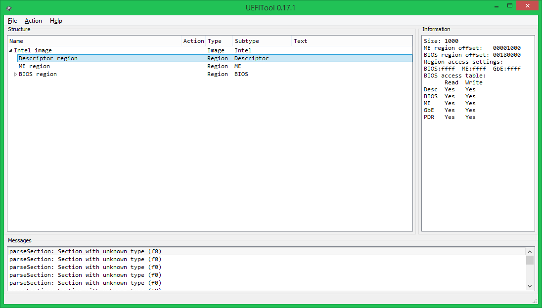
When you select a Descriptor region, you can find out the access settings for regions; in this case, full access, but such settings are very rare. Intel recommends that equipment manufacturers block access to the ME region for reading/writing and the Descriptor region for writing, which is why on most boards it is almost impossible to take a full dump without “dancing with a tambourine” using built-in tools. When you select the ME region, you can find out the ME firmware version, but if it is not displayed, this is not good and it is better not to sew such an image.
Let's move one level lower, to the contents of the BIOS region: 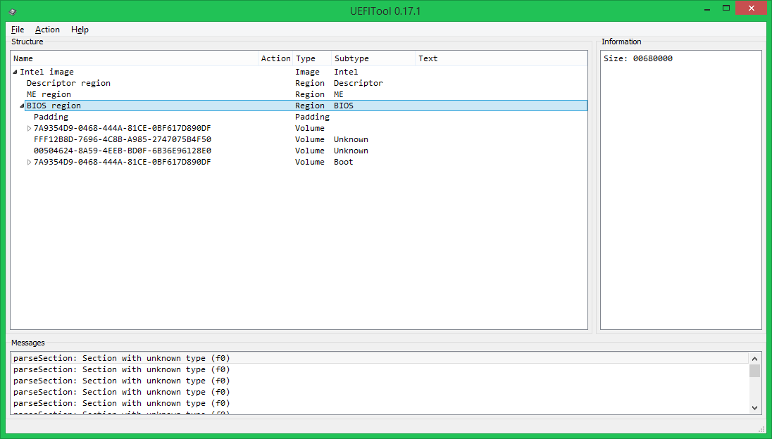
At this level, two types of elements can be found: volumes and free place. Free in this case is not necessarily empty, for example, in this image at the very beginning of Padding the EC firmware is stored.
Volumes are divided into ordinary (the file system format is known), boot (the FS format is known, they contain Security Core, they should be changed with extreme caution) and unknown (either the FS format is unknown, or parsing has not yet been implemented). In our case, the first volume after the free space at the beginning is normal, then two unknown ones (in fact, the first one stores NVRAM, and the second one stores keys and a database for SecureBoot, but I haven’t explained this to the program yet), the last volume is bootable .
Let's now open a regular volume; in this case, it stores files loaded in the DXE phase. 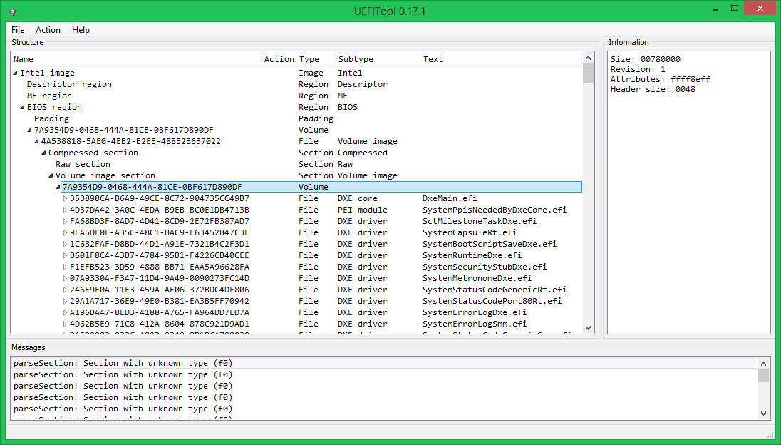
This structure (the main volume inside a compressed section) is used quite often; it allows you to save a decent amount of space on the chip. There is also an option to compress not the entire volume, but each file separately - this is somewhat less economical in terms of space, but such UEFI will start BIOS is faster, because there is no point in unpacking files that have not been accessed.
Now let's look inside the file: 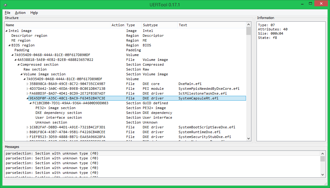
All data in it is stored inside a GUID-defined section (the header of such sections usually stores a digital signature or a checksum, in this case - 4 bytes, similar to a CS, which, however, no one checks), and is divided into 4 sections: image PE32 - actually executable file in PE/COFF format, DXE dependency section - determines the loading order of DXE drivers, UI section - it stores the text “SystemCapsuleRt.efi” in Unicode format and an unknown section like 0xF0 (most likely, its contents are somehow related to the above KS).
All this is good, of course, but editing is not yet visible. No problem, call for any element context menu, which shows what can be done with this element. 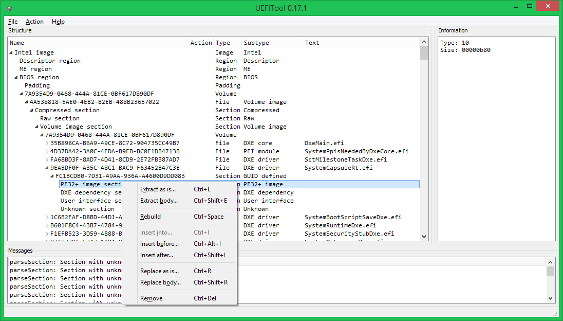
And you can do the following:
- save the element to a file either entirely (Extract as is) or just the data, without headers (Extract body)
- rebuild the element (Rebuild), in this case, while saving the modified image for it (and all its parent elements) sizes and checksums will be recalculated, alignment will be corrected, i.e. the image structure will be brought into compliance with the UEFI PI specification
- insert an element from the file, either before the selected one (Insert before), or after (Insert after), or inside it (Insert into, in this case nothing can be inserted inside the PE32 section)
- replace an element with another element from the file, either entirely (Replace as is) or just its body (Replace body)
Usage example
Let's take an example of a modification that is useful for MacOS X users on PCs: bypassing the setting of the LOCK bit (0x0F) in the MSR_PMG_CST_CONFIG_CONTROL (0xE2) register. This bit is set by the PowerManagement DXE driver to prevent the OS from managing the CPU multiplier by writing to this register. For Windows and Linux this is not a big problem, but MacOS X cannot tolerate such impudence from UEFI. You can, of course, patch the AICPM.kext driver (in 10.8) or the kernel (in 10.9), but it’s better to patch the DXE driver and not be afraid that the next automatic update will break the download. This patch is needed only for systems based on Intel processors SandyBridge, IvyBridge and Haswell and their *-E variants and it’s done like this:We flash the resulting image with the same SPI programmer that was used to make it, and we get no kernel panic when loading MacOS X.
Details, other modifications, conclusion
If you are wondering where the magic pattern “75080FBAE80F” came from and what other patches are worth paying attention to, read the second part of this article, which will be published a little later. In it I will try to prepare more examples in the format “what kind of modification is it, why is it needed, how to do it, by whom and how it was found”, without going deep each time into exactly how to remove the element to be modified and how to insert it back.I hope that the article did not seem too boring and tedious. If you have questions or suggestions, I will be glad to listen and answer to the best of my ability. I will be even more grateful for bug reports. Thanks in advance and good luck with the firmware.
P.S. Dear administration and UFO personally, please make a UEFI hub for posts like this.
It has been said many times, but the advice still remains relevant: “Think ten times before updating the BIOS.” But psychology is powerless against the thirst for something new. Especially in situations where you need to get the hidden potential built into the computer by the manufacturer.
Obstacles and obstacles on the way to your goal are not a hindrance! If it doesn't work out " in science", fiction will come to the rescue. So, in a situation where AMIBCP cannot cope with editing the BIOS image, using workarounds you can achieve a successful result.
Flash Images Tool
A significant drawback of home-grown technologies is not only the difficult path to knowledge of the truth, but also the limited horizons. Each of us is well aware that in technology it is better not to use brute force, but with a special tool. It is this approach that allows you to understand all the nuances of the process under study and delve into all its subtleties. The question is simple: what should a modern computer scientist's toolkit be like?
The first part of the question is followed by a pre-prepared proactive answer: today we will talk about Flash Images Tool - software product to work with an image stored in Flash System ROM fees. Here and further we will use the following terms:
- Flash ROM image - a binary file that can be written to or read from a storage device (usually SPI chips today) on board a personal platform. Its contents guarantee full-time job computer, primarily because as part of the image flash drives there is a region where the BIOS is stored motherboard. Detailed description Flash Image regions are available in the System Tools User Guide for Intel® Management Engine Firmware 6.0.
- BIOS image for Flash ROM chip - binary code included in Flash image ROM. Having been extracted from it, this binary code can be saved to a file that should be called a BIOS file, which in turn can be manipulated using the AMIBCP utility. It follows that the AMIBCP utility works with the image flash drives does not support, but allows you to manipulate only the AMIBIOS image, as you can see by reading the article “AMIBCP and modern versions of AMIBIOS”.
Now it is quite obvious that the advantage of the Flash Images Tool over AMIBCP is the “ability” to work with a flash drive image. This is the merit of the developer, the company.
Launching the FTool utility
Working directory for Flash utilities Images Tool, abbreviated and henceforth - FTool, select the directory d:/amibcp. Running the utility for the first time without the file accompanying it, as usual untitled.xml, the user is warned by a message LoadXmlConfig: Fail to load the XML configuration file “untitled.xml”, and in the protocol ftool.log a message is entered Loaded default configuration.
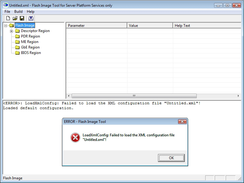
After setting the default configuration parameters, the utility is ready to work, and we can verify this by referring to the option for help About Flash Image Tool…

Before you start editing the BIOS image for the Flash ROM chip, you need to set the utility environment parameters:
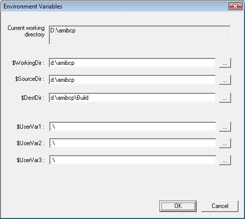
If you want to place the results of the FTtool utility not in the d:\amibcp\Build directory, you should adjust the field $DestDir on the menu Environment Variables properly.
The next step towards achieving the result should be to download the file with the original BIOS image. In our case, this is the file amibios.rom, four megabytes in size.
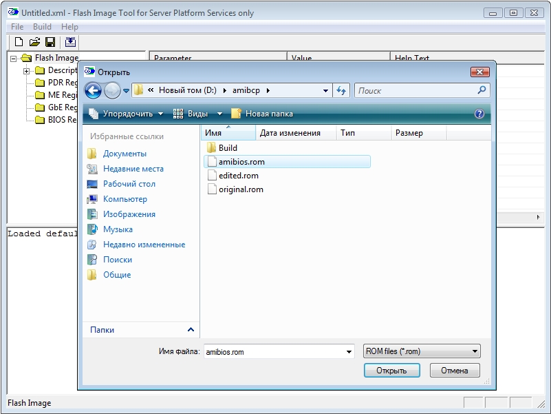
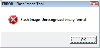
An attempt to download the first file you come across (for example, your favorite melody in MP3 format) will not be successful because FTool analyzes the structure of the Flash image. In case of an error, execution of the utility is terminated with the message Unrecognized binary format!
A successful download causes the FTool utility to create a directory amibios ( with the same name as the image for the flash memory chip) and places the results of its decomposition there:

Content amibios.rom as separate files with extension *.bin, namesake regions stored in Flash Images, is placed in the directory Decomp located inside the directory amibios.
The results of decomposition of the BIOS image for Flash ROM can be viewed in the file amibios_MAP.txt:
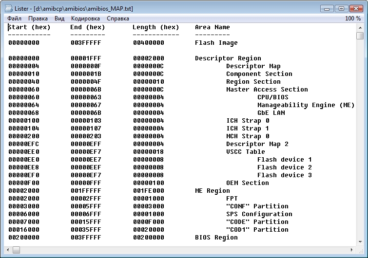
Access to content, i.e. to all regions and partitions (sections) of the file amibios.rom listed in the Area Name column provides the FTool interface. For us further work with the BIOS code, you will be interested in its unpacked image, which is available at d:\amibcp\amibios\Decomp\ as a file BIOS Region.bin. This file is required by the AMIBCP utility to modify parameters CMOS Setup and control some other BIOS functions.
P.S.
Website "New Technologies"
especially for Composter.
There are probably no users today who have not heard of BIOS. Beginner users (some have been in the beginner state all their lives) are afraid of this very BIOS like fire and have no idea how to enter it, let alone configure it. well and experienced users or, as they are commonly called, computer enthusiasts, not only configure BIOS system, but they also reflash it. It should be noted that the BIOS flashing procedure even for specialists causes a surge of adrenaline, since it is by no means safe and often poses a threat to life. However, the procedure for flashing the BIOS is still a piece of cake. Much more extreme is modding, or editing, BIOS, which will be discussed in this article.
Before we start talking about ways to edit the BIOS, let us briefly recall what a BIOS is, what capabilities it provides to the user, and why it should be updated, much less edited.
What is BIOS
BIOS (Basic Input/Output System) is basic system input/output. More precisely, BIOS is a system for configuring and managing memory, processor, chipset, controllers integrated on the board and devices connected to the board. Unlike most other programs, BIOS is not located on the hard drive, but on a special chip with self-powered on the system board.
A lot depends on the BIOS in a computer. In fact, the BIOS defines the system settings that determine the functionality and performance of the PC. Often, the first BIOS versions with which motherboards appear are replete with “bugs” that disappear only in subsequent versions.
The BIOS system is included in any motherboard (with the exception of boards for Apple computers), whether it is for a desktop PC or a laptop. However, traditionally, the BIOS for a laptop has a minimum of settings and is more of an informational nature. Concerning Motherboard BIOS boards for desktop PCs, then it allows you to perform enough a large number of settings that affect both system performance and functionality. In particular, traditional system overclocking, which involves increasing clock frequency processor, changing the processor supply voltage, changing the clock frequency, timings and memory supply voltage are made in the BIOS settings. In addition, in some cases, the BIOS allows you to configure the speed mode of the fan installed in the processor cooler and additional fans installed in the system, and configure a RAID array hard drives in case this array is created on the basis of a controller integrated into the chipset, and also perform a lot of other fine settings computer.
The BIOS is located in a ROM memory chip (Read Only Memory), which ensures that the BIOS is always available regardless of the functionality of components external to the motherboard (for example, boot disks). Since access to RAM ( random access memory) is carried out much faster than to ROM, many manufacturers provide at power-on automatic copy BIOS from ROM to RAM. The area of RAM used in this case is called Shadow ROM.
Currently, most modern motherboards complete with microcircuits Flash BIOS, the code in which can be rewritten using special program. This approach provides the possibility of updating (firmware new version) BIOS.
Manufacturers BIOS kernels not so much. The most common BIOS are from AMI companies ( American Megatrends, Inc.), AWARD and Phoenix Technologies. Other BIOS (from FirmWorks, Micro Firmware, etc.) are much less common. AMI BIOS currently dominates the market, so in the future we will focus on ways to flash and modify it.
Naturally, each manufacturer makes its own changes to basic version BIOS, and, of course, one or another BIOS version is intended only for a specific product (computer or laptop) and is incompatible with other solutions.
Finally, we note that currently BIOS chips use two interfaces to connect to the motherboard: either the LPC (Low Pin Connection) bus or the new SPI (Serial Peripheral Interface) bus.
Why flash the BIOS?
All manufacturers of motherboards and laptops strongly do not recommend flashing the BIOS unless absolutely necessary. Moreover, representatives of service centers constantly turn to motherboard manufacturers with a request to completely block the user’s ability to flash the BIOS. Of course, this idea is absurd and this will never happen, but we emphasize once again that the BIOS flashing operation is unsafe and can pose a threat to life. If the board or laptop is working fine, then there is no point in updating the BIOS.
At the same time, situations often arise when updating the BIOS is necessary. For example, you purchased a motherboard with a processor and found out that they are incompatible with each other. Most likely the problem is that your motherboard has firmware old version BIOS that does not support new processor. The only option in this case is to find old processor and update the BIOS on the board.
In addition, each new BIOS version corrects errors made in previous versions, so the BIOS update procedure turns out to be very useful.
The most secure procedure for flashing the BIOS of boards Gigabyte companies, ASUS and MSI, which implement protection against unsuccessful flashing BIOS. Gigabyte boards are equipped with two BIOS chips (DualBIOS technology), and if the BIOS is not flashed correctly and the system cannot start, the procedure begins automatically disaster recovery BIOS from backup chip.
On new ASUS motherboards, emergency BIOS recovery called ASUS CrashFree BIOS 3. The essence of this technology is that in the event of a BIOS crash or mismatch checksum after unsuccessful firmware, a program is automatically launched that searches for the BIOS on a CD/DVD disk, floppy disk or flash drive (with the FAT/FAT32 file system). If a file is found on some media, the recovery procedure starts automatically.
A similar technology, called M-Flash, is available on MSI boards. The only difference is that the BIOS file must be on a flash drive.
Methods for flashing BIOS
All motherboard manufacturers, along with new BIOS versions, also post utilities for flashing their firmware, as well as detailed instructions, how to flash the BIOS. Alas, there is simply no universal toolkit for flashing the BIOS. In general, there are three ways to flash the BIOS: from DOS, from operating system Windows and directly from the BIOS.
Actually, about ways to flash the BIOS from under BIOS and using proprietary utility from under the operating room Windows systems There's not much to tell. Everything here is simple and clear. Moreover, the method of flashing the BIOS from under the BIOS is the simplest and safest, however, alas, not all manufacturers support this function. The only exceptions are ASUS and Gigabyte.
Moreover, not all manufacturers provide their boards with utilities for flashing the BIOS from Windows, and in some cases, flashing from DOS is the only possible method.
The method of flashing the BIOS from DOS can be called classic, but also the most inconvenient. The fact is that, in addition to having the appropriate DOS utility, this method of flashing involves booting the computer not from hard drive, and with external media. Previously, ordinary 3.5-inch boot floppy disks with DOS were used for this, and the BIOS file itself and the DOS flashing utility were written to this floppy disk, along with the operating system. However, at present, 3.5-inch floppy disks, like floppy drives themselves, can be considered outdated devices. Many modern motherboards do not even have a connector for connecting a floppy drive, and laptops with 3.5-inch floppy drives have not been produced for a long time. However, the problem this method Flashing the BIOS isn't even about that. In the end, you can find a 3.5-inch floppy drive with a USB interface, but this is unlikely to solve the problem. The fact is that a modern BIOS can be several megabytes in size and simply cannot fit on a floppy disk.
In principle, you can try to solve this problem, using instead boot floppy bootable flash drive with DOS kernel. But even in this case, complications arise. First of all, you need to find a utility that will allow you to make the flash drive bootable, and system files operating room DOS systems. On the Internet you can find several utilities that allow you to make bootable flash drives with DOS, the most famous of them are HP USB Disk Storage Format Tool and BootFlashDOS, which are freely available on the Internet.
The HP USB Disk Storage Format Tool utility allows you to create bootable flash drives if you have system DOS files, that is, it also requires the files themselves. However, on torrent resources you can find assemblies that include DOS system files.
If you use flash drives with a capacity of less than 4 GB, when formatting and creating a bootable flash drive using the HP USB Disk Storage Format Tool (Fig. 1), you can use a file FAT system or FAT32, but if you are using a flash drive with a capacity of more than 4 GB, then you need file system FAT32.
Rice. 1. Creating a bootable flash drive with DOS
using the HP USB Disk Storage Format Tool
The BootFlashDOS utility allows you to create bootable flash drives with DOS by pressing just one button, since all the necessary system files are already included in the utility itself (Fig. 2).
![]()
Rice. 2. Creating a bootable flash drive with DOS using the BootFlashDOS utility
In principle, if you create a bootable flash drive with DOS, then there will be no problems with flashing the BIOS. It is enough to copy the DOS utility for flashing the BIOS and the BIOS file itself to a bootable flash drive and boot the computer from the flash drive. To boot your computer from a flash drive, you need to insert it into the PC, reboot, or simply turn on the computer and at the boot stage enter the BIOS to set the settings to boot from USB Flash Drive. Next, having saved the settings, reboot the computer and, having loaded DOS, execute the required command on the command line in accordance with the BIOS manufacturer’s instructions.
We will give examples of executing such a command a little later, but for now we’ll look at another way to flash the BIOS from DOS. It consists in using a bootable CD/DVD instead of a bootable flash drive. It’s hardly worth reinventing the wheel here - it’s better to use a ready-made Hiren’s BootCD (current version 10.4), the image of which can be downloaded from the website www.hirensbootcd.net. In case of use boot disk Hiren`s BootCD will additionally require a flash drive (with file structure FAT or FAT32), on which the DOS utility for flashing the BIOS, and the BIOS file itself must be written.
Now let's look at the procedure for flashing the BIOS from DOS using an example MSI laptop GX640 with AMI BIOS. On MSI laptops, there is only one way to flash the BIOS from DOS using the proprietary DOS utility included with the BIOS file itself. Actually, all you need to flash the BIOS is to create a bootable flash drive, download the archive with all necessary files, which includes a BIOS file, a flashing utility and an executable file flash.bat with a written sequence of all actions. After this you should unzip this archive to a bootable flash drive and, after booting from the flash drive, run the flash.bat file for execution. The main thing is that all unzipped files are in one folder (you can unzip them to the root directory of the flash drive).
In general, it should be noted that for each type of BIOS (AMI, Award) there are specialized utilities from AMI and Award for flashing. For example, from the AMI company website you can download the amiflash package, which includes the afudos and afuwin utilities, which allow you to reflash the AMI BIOS from DOS and from Windows, respectively. However, you need to keep in mind that AMI BIOS can be either a classic AMI BIOS or an AMI Aptio BIOS. Aptio is a type of AMI BIOS, but the main thing is that AMI BIOS and Aptio AMI BIOS are used various utilities afudos and afuwin.
In addition, many motherboard manufacturers make such significant changes to the BIOS for their products that universal utilities AMI or Award simply do not recognize them, and therefore cannot reflash them. In particular, in the AMI example discussed earlier Laptop BIOS MSI GT640 the afudos and afuwin utilities do not recognize it as an AMI BIOS and, naturally, cannot reflash it.
In general, the situation when it comes to modified versions of AMI BIOS, which are defined as AMI BIOS by the AMI utilities themselves, occurs quite often. This and many MSI boards, and many Gigabyte boards. The only ones not seen in such “show off” so far are ASUS boards, the BIOS on which can be flashed using utilities from AMI (although, of course, utilities supplied by ASUS itself are better suited).
Why modify the BIOS
So, we have looked at the main ways to flash the BIOS, and now we will discuss how you can modify it. Naturally, the question arises: why modify the BIOS at all? One can argue endlessly about this, as well as about whether it is necessary to overclock a computer. Actually, if the BIOS modding procedure is possible in principle, there will always be enthusiasts who will do it.
Just a few years ago, few people thought about the possibility of editing the BIOS themselves. However, in Lately this procedure has become popular, and you can find many resources on the Internet dedicated to BIOS modding. Interest in this issue can be explained by the fact that recently many users have begun to flash the SLIC table in their BIOS, and this is one of the options for modding, or editing, the BIOS. The procedure of flashing the SLIC table in the BIOS itself is quite legal, but the purpose for which it is done, of course, is already illegal - this is precisely what explains the popularity of this procedure.
Let us briefly explain what we are talking about we're talking about. Flashing the SLIC table in the BIOS is used to implement the OEM activation mechanism for the Windows 7 operating system in the same way as Microsoft OEM partners do to activate pre-installed copies of Windows without Microsoft checks. This method allows you to activate the system subject to three conditions: the use of a special OEM key and OEM certificate, as well as the presence of an SLIC table in the computer BIOS.
Windows 7 requires SLIC tables version 2.1 in the BIOS, and there is no strict binding of the OEM key to the SLIC table and certificate. The key is only tied to Windows edition and allows you to activate both x86 and x64 versions of the OS. The file certificate and SLIC tables are interrelated, and for successful activation both components must be from the same OEM partner.
We will not tell you how to illegally activate Windows 7, but we will focus on the procedure for inserting an SLIC table into the BIOS. Let us immediately note that this is not always possible and not all BIOS can be edited in any way.
You can find a package on the Internet software tools(AMITool), containing both the SLIC tables themselves and the utility (AMI SLIC Mod) for flashing them into the AMI BIOS. However, for this you need to use AMI BIOS on your board, but even in this case there is no guarantee that the procedure for flashing the SLIC table in the BIOS will be possible. As we have already noted, many manufacturers modify the BIOS for their products in such a way that the AMI SLIC Mod utility simply does not recognize it as an AMI BIOS, and therefore cannot modify it.
However, even in this case, you should not despair and run to the store for another motherboard. Before attempting to flash an SLIC table in the BIOS, you should check whether it is missing from the BIOS. If you bought a motherboard or laptop recently, then it may well turn out that the version of the SLIC table you need (version 2.1) is already available in the BIOS.
You can view the version of the SLIC table in the BIOS using the specialized utility RW - Read & Write Utility (current version 1.4.7), which can be downloaded from the website http://rweverything.phpnet.us. Another name for this utility is RW-Everything.
Having installed this utility, launch it and in the main program window on the toolbar, click on the button labeled ACPI. In the ACPI Table window that opens, click on the SLIC tab. Next, you need to view the table in hexadecimal format and find a line in it starting with byte 53 20. If the next four bytes are 00 00 00 00, then the BIOS has the SLIC table version 2.0 flashed, and if - 01 00 02 00, then the SLIC table is flashed table version 2.1 (Fig. 3).

Rice. 3. Determining the BIOS SLIC table version
Of course, embedding a SLIC table into the BIOS is far from the only option for possible modding. Another way of modding is to unlock some BIOS functions. Indeed, motherboard manufacturers often deliberately block some functionality BIOS to simplify the procedure Setup settings BIOS. They also disable those functions that are not present in a particular motherboard, but can be used in the following modifications.
Using specialized utilities, you can try to unlock all disabled functions and options in the BIOS. You can also change logos (some motherboard manufacturers, e.g. ASUS company, they even supply special utilities to change the BIOS logo), as well as some names, so that, for example, when loading, not the real name of the processor is displayed, but something like “ AMD Core i9-995".
Another example of BIOS modding can be given. Some craftsmen manage to unlock the ability to use SLI mode through the BIOS for NVIDIA video cards on those motherboards where this mode not provided. Actually, if a board officially supports SLI mode, then its BIOS has the corresponding key from NVIDIA. The idea of modding is to cut this key from the BIOS of the board on which SLI mode is officially supported, and insert it into the BIOS of the board on which SLI mode is not supported (that is, in the BIOS without the NVIDIA key). In particular, there are examples of how, due to such modding, the SLI mode was activated on boards based on Intel chipset P45 Express.
However, let's move from theory to practice and discuss editing BIOS, in particular editing AMI BIOS as the most common.
Editing AMI BIOS
To edit a BIOS with an AMI kernel, you will need the AMIBCP utility, which, by the way, is produced by AMI itself. This utility can be downloaded either separately or as part of the AMI BIOS ROM Utilities package. It should be noted that since, as we have repeatedly emphasized, manufacturers of motherboards and laptops make changes to the AMI BIOS for their products, there is no guarantee that the AMIBCP utility will recognize the BIOS. Alas, not every BIOS can be modified. As practice shows, BIOS can be edited without problems ASUS boards and ECS, but for motherboards from Gigabyte and MSI the AMIBCP utility is powerless.
So, let's return to the consideration of editing the BIOS in the case where this is possible. The AMIBCP utility (version 3.x) runs under the Windows operating system, but it should be noted that there are versions of the same utility for DOS.
After downloading the utilities, you need to open the BIOS file. In our example, we will look at editing the AMI BIOS for the ASUS P6X58D-E motherboard using the AMIBCP v.3.37 utility. We will edit the P6X58DE.ROM file.
So, in the main program window we load the BIOS file that we will modify (Fig. 4).
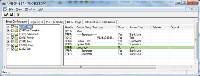
Rice. 4. Main window of the AMIBCP v.3.37 utility
First of all, the Setup Configuration tab is interesting, in which, in fact, the BIOS settings are modified. The left window of this tab displays the main BIOS settings menu. If you uncheck a menu item, it will not appear in BIOS menu. In the example considered (see Fig. 4), we unchecked the Ai Tweaker and Advanced checkboxes, thereby blocking all options for overclocking the system. That is, BIOS menu items in which you can view information about the processor and memory, as well as change frequencies, supply voltage, etc., will simply be absent in modified version BIOS.
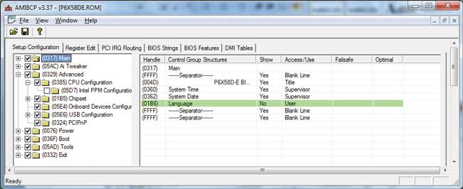
The situation is similar when expanding the tree structure of each menu item BIOS settings: If you uncheck any sub-item, it will not appear in the BIOS menu. For example, if we do not want the menu Advanced settings the Intel PPM Configuration item was displayed, you just need to uncheck the corresponding item (Fig. 5).
In order to block any option in the BIOS setup menu, just set the value to No in the Show column for the corresponding item. Such blocked elements will (after saving the changes) be highlighted with a green bar.
For example, if our system does not have additional fans installed in the case and we do not want their settings items to be displayed in the BIOS, then we enter the Power menu, then open the menu Hardware Monitor and for the options Chassis Fan 1 Speed, Chassis Fan 2 Speed, Chassis Fan 3 Speed, Chassis Q-Fan Profile and Power Fan Speed, set the value to No in the Show column (Fig. 6).
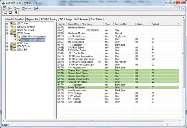
Rice. 6. Blocking the display of various setup menu options in the BIOS
It should be noted that BIOS P6X58DE.ROM for the ASUS P6X58D-E board does not allow any improvements using the AMIBCP v.3.37 utility. All options in it are unlocked, so the maximum that can be done is to block what is not needed (though it is not clear why to do this).
You can also try to change some of the inscriptions, but keep in mind that the inscriptions will not be displayed in Russian. For example, if we want the string ComputerPress P6X58D-E BIOS Edition to be displayed instead of the string ASUS P6X58D-E ACPI BIOS Revision 0106 when loading, then just find the string ASUS P6X58D-E ACPI BIOS Revision 0106 on the BIOS Strings tab and change it to the specified one .
We just have to consider one more type of BIOS modding - changing background picture(logo) BIOS. At the same time, ASUS even completes its boards with a special utility that allows you to implement this opportunity. Of course, for ASUS boards it is easiest to use this utility. However, for AMI BIOS you can also use the OEM LOGO utility from AMI itself (Fig. 7).

Rice. 7. Changing the BIOS logo using the OEM LOGO utility
The interface of this utility is very simple and does not require any comments. Just load the BIOS and specify the path to the file with the new logo. The only limitation is that the drawing must be certain resolution and format.


