How to make an antenna for digital channels. Making an antenna for digital TV with your own hands. Professional antennas for digital TV
So, imagine this situation: in the evening you decided to watch your favorite TV program, and suddenly the TV stopped showing. Or another case: You arrived at the dacha, have already prepared for a vacation, and again the same situation - not a single channel works. What to do in this case? The answer is simple - you need to make an antenna for the TV with your own hands, because most likely the cause of the breakdown is this device. Next, we will look at the simplest creation options, which will require a minimum of available tools and time.
Idea #1 – Use beer cans!
This version of a homemade television antenna is the simplest and fastest to manufacture. Maximum amount The number of channels that will be at your disposal is 7, but this figure may vary slightly depending on the region.
To make a TV antenna from beer cans, you will need the following materials:
- 2 small screws, also called “bugs”;
- 2 prepared beer cans (empty, washed and dried);
- from 3 to 5 meters TV cable(can be taken from a failed device);
- soldering iron and tin (for better fixation contacts), presence is not mandatory;
- screwdriver;
- wooden trempel;
- electrical tape or tape.
Finding all the materials in the house will not be a problem, so having prepared them, we immediately get down to business.
In order to make a homemade antenna from cans, you need to complete the following steps:
- We prepare the cable. First, at a distance of 10 cm from the edge, you need to make an incision and remove part of the top layer of insulation. Having opened access to the screen, we collapse it into one turn. After this, we cut off the middle insulating layer, exposing the thin copper core of the cable. As for the second end of the conductor, there should be a regular plug there.
- We prepare the jars. There will also be no difficulties with containers that will act as signal receivers. First you need to choose the optimal dimensions of beer cans. It is better to use liter ones, but if these are not available, containers with a volume of 0.5 and 0.75 liters will do a good job.
- Let's make contacts. On at this stage the twisted cable screen is attached to one can, and the copper core itself is attached to the other. Fixation is carried out with bedbugs using a screwdriver. In order to make the picture quality on the TV screen higher (signal transmission quality), it is recommended to fix the wire not only with clamps, but also with a soldering iron (tack a little). The result should look like this:

- We assemble a homemade antenna for a TV. The signal receiver is ready, now we are making a supporting structure, which is the trempel. Using electrical tape, we fix the containers to the trempel (as shown in the photo). We draw your attention to the fact that the banks must be strictly on the same straight line, otherwise the homemade product will not work as we would like.

- Setting up an antenna for the TV. Now you need to experiment with the optimal distance between the cans, as well as where to hang the device, so that the homemade product catches many channels. We turn on the TV and determine exactly how the receivers should be located and where is the most suitable place to work. This is where the creation technology ends.

As you can see, the whole process is quite simple and does not represent anything complicated. Optimal distance is 75 mm between the ends of the cans, and the best place installations - near the window. In individual cases, the distance between banks can be made larger or smaller.
Idea No. 2 – Use wire
One more no less a good option, which is advisable to use in the village - a homemade antenna made of copper wire with an amplifier.
All you need for production is:
- amplifier (suitable from an old device);
- two pieces of wire 180 cm each;
- a piece of metal (or wood) plate 15*15 cm;
- electric drill with a set of drills (or welding machine);
- small bolts;
- hammer;
- iron pipe;
- TV cable of suitable length.
So, to make your own TV antenna from copper wire, you need to complete the following steps:

Please note that in the photo examples, both the amplifier, the reflector, and the wire are covered with paint. Painting protects the structure from corrosion and other unfavorable factors, significantly extending service life homemade antenna for TV.
Idea No. 3 – Home HDTV device
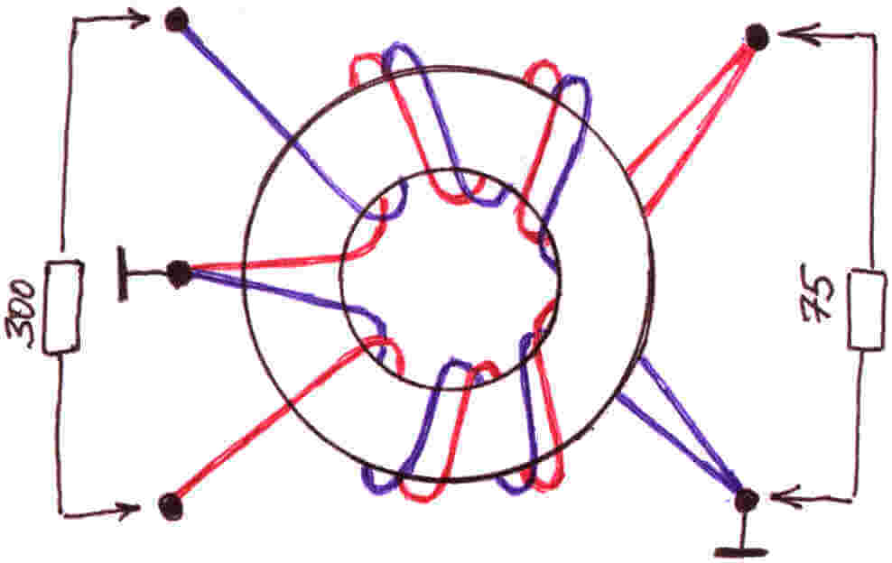
If the first 2 options worked at a frequency of no more than 270 MHz, then next way manufacturing will allow you to enjoy more high-quality picture, because The signal range can reach up to 490 MHz. The only part that is unlikely to be found among household items is a matching transformer from 300 to 75 Ohms. You will need to buy it in advance if you decide to make your own TV antenna as an experiment and improve your skills. Although there are instructions for making a homemade transformer, you can find and use it.

Materials you will need:
- Scotch
- Cardboard
- Stationery knife
- Foil
- Stapler
- Scissors
- Marker
- Roulette
Having prepared all this school kit, let's get down to business!
First you need to sketch (or print on your computer) this diagram:


Now, according to the diagram, we cut out all the spare parts, including the necessary pieces of foil:


After this, you need to make a reflector with dimensions of 35 * 32.5 cm (height and width). Cover one side with foil.


In the middle we cut out two identical rectangles, which are necessary in order to completely assemble the signal catcher of a homemade antenna for a TV. The rectangle should be 3.5 cm long, its purpose is to maintain the distance between the reflector and the auxiliary parts.


We glue the parts onto the rectangle, and when the cardboard homemade product hardens, we drill holes for the television cable.


We connect the transformer and insert the cable into the plug. A more powerful TV antenna is ready for use! It should also be noted here that this option homemade products are only suitable for indoor use, because... paper will quickly deteriorate outdoors.
Another option powerful device made at home:
Idea No. 4 – Apartment option
There is another way to do powerful antenna for a TV from improvised means, which is suitable for both street and apartment use.
To make the device you will need the following materials and tools:
- 4-meter copper wire, cross-section 4 mm2;
- board of arbitrary thickness, 55 cm long and 7 cm wide;
- wood screws;
- ruler or tape measure;
- a simple pencil;
- screwdriver;
- soldering iron;
- plug
So, first, according to the drawing, we drill holes in the board: 
Then we transfer the drawing data to the board and drill in the appropriate fastening points. 
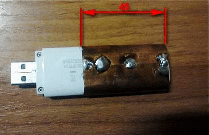
Next, the copper wire must be cut into 8 pieces of 37.5 cm each. 
In the middle of each of the 37.5 cm sections, the insulation must be removed (as shown in the picture). 
We cut off 2 more copper wire sections 22 cm long and roughly divide them into 3 equal parts, again removing the insulation at the inflection points. 
We bend the prepared wire in exposed areas. Please note that for those segments that are bent in half, the distance between the ends must be 7.5 cm ( optimal value to receive a signal from a homemade television antenna). 
Next, we attach the plug to the finished homemade product, and connect the television cable to it. 
 This concludes the manufacturing process. We select a suitable location and install the device.
So we have provided the most simple instructions. We hope that now you know how to make a home TV antenna with your own hands! We draw your attention to the fact that today on the Internet you can find many other options in which inventors do without cans and wire. Among other available means, copper tubes, aluminum disks and electrodes are often used. The advantage of the options we have listed is that you can quickly make such antennas for a TV with your own hands, without spending the whole evening on it.
Related materials:
Visual video instructions for creating a simple antenna from cans
Assembling a digital antenna from a TV cable and a cardboard box
HDTV antenna made from improvised means
Like( 0 ) I do not like( 0 )
Good afternoon, V.Yu.
The visitor in the latest posts with experience on FM radio antennas is me. The antenna turned out to be easy to manufacture and I decided to repeat it for FM reception and compare it with previously made ones, by ear, instrumentation, and ease of use. The goal was to obtain a signal with a minimum of interference for high-quality sound radio in stereo mode. I made two antennas. The first one is made of wire 3 mm thick. The second is made of metal-plastic. Made from metal plastic it turned out to be a little better in terms of the level of received signals. By ear - less low frequencies, more highs and clarity of each instrument in the orchestra.
Measurement method - there is a receiver with a signal level indicator in decibels. We number the FM stations and look at the level of the received signal from the station in dB, then we sum up all the values. We get numeric value antennas according to the parameter the level of the received signal. All antennas were placed under the same directional conditions. Wire on a window 303 cm long in the form of a rectangle with a gap along larger side 2 cm (51 cm x 102 cm) - has a value of 491 dB, a directional loop phased loop antenna made of wire - 459 dB, the same one made of metal - 485 dB. As can be seen from the presented values, the metal-plastic antenna is comparable to a full-size frame equal to length mid-FM waves.
Now on to the manufacturing technology. It is somewhat different from yours and is made without soldering. The base is a rail (30 x 6 x 3 cm). Remained from renovation (2 pieces). Wire antenna - circumference 75 cm (quarter wave mid FM range). Two circles of the same length. We take a light self-tapping screw (not dark - it has a cone head) with a flat head for a Phillips screwdriver. We make a hole in the rail with a drill or other method so that the wire enters the hole with little resistance. You can slightly bend the ends of the wire for this purpose. We insert the two ends of the loop into the hole in the rail and do not connect them to each other (leave 5 mm between the ends of the loop). We do the same with the second loop at the other end of the rail. The distance from the end of the rail is 1 cm. We screw the screws on top of the rail so that the end of the screw fits into the loop wire at the end. This ensures contact of the coax with the frame. Under the self-tapping screws we screw the central core of the coaxial and the braid with different sides framework. For example, the central core is on the left, and the braid is on the right in the direction from the beginning of the rail to its end. We lay the coaxial between the frames and attach it to the screws (screw it under the screw head). The second loop is also attached and the ends of the coaxial are secured under the screws securing the second loop. The descent is in the form of a coaxial - I got a length of 7.5 meters, we fasten it under the screws of one of the frames (the central core is on the left, and the braid is on the right. We tighten everything - the screws ensure contact of the wires with each other with the head, and contact with the loop with the end. The distance between with self-tapping screws - 2 cm We connect the other end of the coaxial cable to the receiver through the connector you need. That's it - the antenna is ready.
Metal-plastic differs in manufacturability. 20 mm pipe, also after repair. Bent into a ring without any problems. Loop length 75 - 1.5 cm (as recommended in the article) = 73.5 cm. Attaching the loop to the rail is also a self-tapping screw, but bigger size so that it passes through the metal-plastic and is well secured to the wood, by 10-15 mm. There is a distance of 1 cm between the ends of one loop. The screws from the end of the loop are still at a distance of 0.5 cm. We get a distance of 2 cm between the screws of one loop. We lay a piece of plastic between the loops and fasten it with screws to the rail, so that the coax can be inserted inside. We connect the coax in the same way as in the first case to the ends of the loop, the central core and the braid. We ground the tube between the antenna loops (connect it to the braid). We insert a piece of coax into the pipe between the loops, connect the c.z. and braid. We also connect the reduction coaxial to the self-tapping screws of one of the loops (central ring and braid). We first clean the ends of the loops from vinyl to aluminum so that the head of the screw presses the wires to the aluminum and at the same time secures the loop to the wooden batten.
With all respect, Andrew
Good afternoon, V.Yu.
The visitor in the latest posts with experience on FM radio antennas is me. The antenna turned out to be easy to manufacture and I decided to repeat it for FM reception and compare it with previously made ones, by ear, instrumentation, and ease of use. The goal was to obtain a signal with a minimum of interference for high-quality radio sound in stereo mode. I made two antennas. The first one is made of wire 3 mm thick. The second is made of metal-plastic. Made from metal plastic it turned out to be a little better in terms of the level of received signals. By ear - less low frequencies, more high frequencies and distinctness of each instrument in the orchestra.
Measurement method - there is a receiver with a signal level indicator in decibels. We number the FM stations and look at the level of the received signal from the station in dB, then we sum up all the values. We obtain the numerical value of the antenna based on the received signal level parameter. All antennas were placed under the same directional conditions. A wire on a window 303 cm long in the form of a rectangle with a gap on the larger side of 2 cm (51 cm x 102 cm) - has a value of 491 dB, a directional loop phased loop antenna made of wire - 459 dB, the same one made of metal - 485 dB. As can be seen from the presented values, a metal-plastic antenna is comparable to a full-size frame equal to the wavelength of the middle FM range.
Now on to the manufacturing technology. It is somewhat different from yours and is made without soldering. The base is a rail (30 x 6 x 3 cm). Remained from renovation (2 pieces). Wire antenna - circumference 75 cm (quarter wave mid FM range). Two circles of the same length. We take a light self-tapping screw (not dark - it has a cone head) with a flat head for a Phillips screwdriver. We make a hole in the rail with a drill or other method so that the wire enters the hole with little resistance. You can slightly bend the ends of the wire for this purpose. We insert the two ends of the loop into the hole in the rail and do not connect them to each other (leave 5 mm between the ends of the loop). We do the same with the second loop at the other end of the rail. The distance from the end of the rail is 1 cm. We screw the screws on top of the rail so that the end of the screw fits into the loop wire at the end. This ensures contact of the coax with the frame. We screw the central core of the coaxial and the braiding on different sides of the frame under the self-tapping screws. For example, the central core is on the left, and the braid is on the right in the direction from the beginning of the rail to its end. We lay the coaxial between the frames and attach it to the screws (screw it under the screw head). The second loop is also attached and the ends of the coaxial are secured under the screws securing the second loop. The descent is in the form of a coaxial - I got a length of 7.5 meters, we fasten it under the screws of one of the frames (the central core is on the left, and the braid is on the right. We tighten everything - the screws ensure contact of the wires with each other with the head, and contact with the loop with the end. The distance between with self-tapping screws - 2 cm We connect the other end of the coaxial cable to the receiver through the connector you need. That's it - the antenna is ready.
Metal-plastic differs in manufacturability. 20 mm pipe, also after repair. Bent into a ring without any problems. The length of the loop is 75 - 1.5 cm (as recommended in the article) = 73.5 cm. Attaching the loop to the rail is also a self-tapping screw, but of a larger size so that it goes through the metal-plastic and is well secured to the wood, by 10-15 mm. There is a distance of 1 cm between the ends of one loop. The screws from the end of the loop are still at a distance of 0.5 cm. We get a distance of 2 cm between the screws of one loop. We lay a piece of plastic between the loops and fasten it with screws to the rail, so that the coax can be inserted inside. We connect the coax in the same way as in the first case to the ends of the loop, the central core and the braid. We ground the tube between the antenna loops (connect it to the braid). We insert a piece of coax into the pipe between the loops, connect the c.z. and braid. We also connect the reduction coaxial to the self-tapping screws of one of the loops (central ring and braid). We first clean the ends of the loops from vinyl to aluminum so that the head of the screw presses the wires to the aluminum and at the same time secures the loop to the wooden batten.
With all respect, Andrew
The popularity of the Internet among the population is constantly growing. However, many people live in places where the signal is very weak or non-existent. In this regard, the problem of increasing the power and quality of Internet reception becomes very acute. Slow speed takes a lot of time and does not give the desired result. Therefore, an external Kharchenko antenna, designed in the form of a thick copper wire, often comes to the rescue. The connection with a square to each other occurs in places of open corners, where the television cable is connected.
Such an antenna requires precise calculation for digital terrestrial television. To improve directivity, some designs may include a grille or solid screen made of conductive material. Such a biquad antenna allows you to solve many problems with signal reception and Internet speed. Homemade designs, including Various types Kharchenko antennas are made relatively easily and include metal and plastic parts, as well as elements from other materials, connected different ways. Similar designs can be easily made independently, including the Kharchenko antenna for TV with your own hands.
Kharchenko antenna for modem
Currently, many users are looking to increase the speed of their mobile internet. This problem is especially acute for those who live at a considerable distance from base station using the Internet at very low speed. In such situations, most the best way out from the situation becomes a Kharchenko antenna for a 3g modem with your own hands, which is quite easy to make at home.
This frame structure is known as UHF antenna since the 60s of the last century. It has a zigzag frame configuration which makes the device very efficient.
The system consists of two square elements. In order to calculate the antenna for a 3g modem at a frequency of 2100 MHz, the size of each side of the square must be 53 mm. The entire design is made in the form of an interlocking structure, including two diamond-shaped figures with internal angles of 1200. This is done in order to reduce internal resistance devices. The diamonds are connected to each other by soldering. The high-frequency cable is also soldered here.
More accurate data can be obtained using online calculator to calculate the Kharchenko antenna, into which you just need to enter the necessary initial data.

To increase efficiency, the device can be used in conjunction with a reflector. Usually this part is a metal plate, and the most suitable material for its manufacture is foil PCB. IN in this case antenna includes determining the distance between the receiving device and the reflector. After calculations and procurement of materials, a Kharchenko antenna for the modem can be made with your own hands.
The parts are connected to each other using hot-melt adhesive. Commit required distance between the elements you can use any object with the most suitable sizes. Then the antenna is connected to the device. Since modems do not have connectors for connecting external antennas, they are simply wrapped with wire, which is then connected through a cable to the receiving device. If necessary, a Kharchenko antenna for a 4g modem can be made using the same scheme.
Upon completion of assembly, at the opposite end of the cable that will connect to the modem, you need to assemble a so-called matching device, designed specifically for such devices. For this purpose, copper foil is used, the same as in printed circuit boards. The calculation of the antenna for the 4g modem is the same as in the previous version.
If there is a connector for external antenna, the cable is connected using a special adapter. After all connections, the antenna for the modem is considered ready for use. Setting up signal reception for 4g is done experimentally by slowly rotating the structure around its axis until the clearest signal is obtained. The quality of the signal is determined by the number of lines on the icon displayed on the computer or mobile phone.
Kharchenko antenna for digital TV
For work digital television The decimeter wave range is used. Therefore, before designing, Kharchenko antennas for DVB t2 should be made in order to maximize signal reception.
The design itself looks quite compact, is made in the classic version from two rhombuses, the result is a zigzag antenna without a reflector. Any conductive material can be used as a base, for example, a copper or aluminum conductor with a diameter of 1-5 mm. Tubes, strips, corners, profiles, etc. are also suitable. Copper wire 3 mm thick is best suited for these purposes. It bends, aligns and solders very easily. Next must be manufactured in a certain sequence. The resistance of the television cable should be approximately 50-75 Ohms.

Quality digital signal does not depend on distance, as happens in analogue television. In this case, when the TV antenna is working normally, the signal enters the TV receiver normally, but if there are malfunctions, then there will be no signal at all. Accordingly, there will be no image. If there is a signal and it is received normally, then the image will be of the same quality on all channels. This factor must be taken into account when performing for digital TV, although individual settings may be different for a particular region.
Directly TV antenna Kharchenko is made in a certain sequence:
- First you need to measure a piece of wire with a total length of 112 cm and bend it, keeping the dimensions of the sections alternately 13 and 14 cm.
- After all the bends, two ends are formed, which must be stripped to a distance of 1.5-2 cm. Loops are made at the ends and fixed to each other. The joints are completely sealed. Then, the central core is soldered to one of the joints, and the braid to the other. The result is a finished antenna or double square.
- Biquad antenna for a TV requires a television cable of approximately 3 meters. From the antenna side it is stripped by 2 cm, and from the plug side by 1 cm. The plug can be chosen at your discretion. Just like the wire, it needs to be cleaned using a needle file or some sharp object. Thus, the Kharchenko zigzag antenna for digital TV is almost ready for use.
- After soldering is completed, all joints should be filled with hot glue from a gun. While the glue has not cooled, its excess must be collected. The result is a connection that is both reliable and elastic. On the antenna itself, the soldering points are also filled with glue.
Kharchenko antenna for phone
A remote directional antenna can significantly increase the capabilities of a mobile phone and improve the quality of communication when the subscriber is in a remote area. It is not always possible to find the most suitable option on sale, so the best way out is the Kharchenko antenna for cellular communication, made from scrap materials with your own hands.

Most affordable option is the standard design discussed above. Such an antenna should be sized based on specific operating conditions. All necessary materials sold at a hardware store. The simplest designs can connect directly to the cable and do not require any special settings.
First of all, you need to stock up on copper wire with a diameter of 2-3 mm. You can take an insulated wire and strip the insulation from it. If connections are to be made without soldering, special F-type antenna connectors and connectors will be required. When you plan to connect two Kharchenko antennas in parallel, you may need a reflector, which can be tin or aluminum. The joints are insulated using heat shrink tubing or electrical tape. For soldering connections you will need a soldering iron.
Copper wire, prepared in advance, is bent and turned into a zigzag frame, representing two diamonds. The sides of each of them are 80 cm long, and the total distance between opposite corners will be 226 cm. Next, the antenna calculator determines the point of connection of these diamonds as the point of connection with the cable. A piece of cable measuring 50 cm is soldered to this point, and an F-type connector is screwed to its opposite end. Next, the main cable of the required length is connected to the connector.

In some cases, calculating the Kharchenko antenna online involves installing a reflector that significantly enhances signal reception in a certain area. The design is the same as the antenna for T2, when the lower end of the frame and the reflector are connected to each other through the cable braid. For this purpose, a 50 mm long bolt is additionally screwed into the reflector, to which the F-type connector is attached using a tie. A cable and a frame located at a distance of over 40 mm are first soldered to this connector. Thus, Kharchenko’s antenna for a mobile phone, made independently in the most simple version, ready to use.
To directly connect the receiving device to mobile phone a pigtail is used, which is a special wire. One end of it is connected to antenna cable, and the other using a connector with the phone's antenna socket. In this case, there is no problem calculating the antenna and there are no separate settings are not required, it is enough just to position the antenna in the most optimal way, focusing on the quality of the received signal. It is recommended to install the mast with the receiving device as close to the house as possible, preferably near a window, in order to minimize the cable length.
At the beginning, I would like to inform you that there are no “digital” antennas. Any UHF antenna will be suitable, specifically for Sochi, operating in the range 32 and 53 frequency channels. If you live in a place where there is direct visibility to the Sochi television center, then indoor antenna(do not choose an antenna with a built-in amplifier) and even an antenna made from a piece of television cable will suit you quite well, considering that the first multiplex broadcast on 32 channel goes with an excess level compared to the level of the second multiplex on channel 53, so we will tune our whip antenna to channel 53.
To do this, take a piece coaxial cable RG-6 60-70cm, one end is terminated with an F connector and an adapter for connecting to the antenna socket of the TV. At the other end, the central core of the cable is exposed. Based on the calculation that channel 53 is at a frequency of 730 MHz, which is approximately 41 cm, this means that we expose 41 cm of the central core (you can use half of this or even a quarter). Next, we fix our antenna directly on both sides with tape. back cover our TV, the antenna is ready!
Not all residents of Sochi live in direct visibility to the television center, than more difficult conditions reception, the higher the gain the antenna will be required. I want to warn against the illiterate use of amplifiers TV signal, most good amplifier This good antenna, and if there is no signal from your antenna, then there is nothing to amplify. Moreover, the amplifier can also ruin what was in the antenna. The fact is that the entire city is covered by a network of cell phone towers, and the G-2 standard uses the 900 MHz range, which easily penetrates the antenna amplifier and leads to intermodulation distortion, which does not allow the DVB-T2 tuner to work normally, as a result of which the TV writes , "no signal".
To avoid this, LTE filters are used, which cut out what is above 850 MHz. The first multiplex does not call special problems with its reception, as it is broadcast from many repeaters in the city: Moldovka, Ermolovka, Cossack Brod, Golitsyno, Kepsha, Kudepsta, Matsesta, Dagomys and a dozen in the Lazarevsky district.
The second multiplex can only be received from the television center of the Central District and the repeater in the village of Veseloye. To receive a signal remotely from a television center, it is necessary to use an antenna with a high gain of 16-18 dB and a channel amplifier 53 television channel. I will say right away that the amplifier cannot be assembled under amateur conditions. But you can build an antenna tuned to TV channel 53.
The 25-element “wave channel” antenna consists of a four-element reflector, loop vibrator, twenty directors and traverses. The antenna elements are made of wire or tubes with a diameter of 4-5 mm; they are attached in any way to the supporting boom (crossbeam), which is made of a rectangular tube with a side of 20 mm. The gain of such an antenna reaches 17 dB, the opening angle of the main lobe of the radiation pattern in the horizontal and vertical planes is 28-30 degrees. When installing this antenna, it is necessary to provide the ability to adjust the antenna not only horizontally, but also vertically, because the envelope wave always comes from above and a couple of decibels, which can be gained in conditions of poor reception, will not hurt. Antenna amplifier, preferably channel (53 k) must be installed on the mast closer to the antenna. The antenna is matched with the descent cable using a half-wave U-shaped elbow.
p.s. The article was written by my father, especially for Sochintsy :)


