Homemade Wi-Fi antenna for a router. Homemade Wi-Fi antenna
I will show you how to assemble a very powerful antenna for receiving Wi-Fi, capable of receiving a signal over a distance of many kilometers, but at the same time lightweight and easy to assemble. Having crossed two popular antennas, a wave channel and a pouch antenna, I got the idea to create a Wi-Fi gun.
This antenna can be made from any sheet of metal. I used 0.3mm thick copper foil because it is easy to cut with scissors.
The parts of our antenna will be mounted on a pin; we need to cut 7 disks with a hole in the middle.

To do this, you need to place, punch or drill seven holes, and only then circulate the circle. If you do the opposite, the drill may go to the side, but for us it is important that the hole is exactly in the middle.
We scratch out a circle according to the dimensions indicated in the diagram and cut out our disks.
 Picture 1.
 You need to do it as accurately as possible, a deviation of just a millimeter will not work correctly. The thickness of the metal and the diameter of the pin have almost no effect on the operation of our blaster and can be anything. We get these circles (See Fig. 1) and after all the parts are cut out, all we have to do is screw them onto a pin, observing the size of the gaps between them.
This irradiator is easy to assemble, like a construction kit. We install the second plate of our
blaster at a distance as indicated in our diagram - 30 millimeters, by tightening the nuts we select exactly our 30 millimeters.

On the last two disks you need to make a hole for the wire. Our blaster is ready. Now all that remains is to connect it to our device. At first it will be a USB modem, then we will connect it to a smartphone and finally to a router to distribute the Internet through our WI-FI gun.
To connect to the Wi-Fi whistle, you need to carefully disassemble the antenna so as not to damage the wire. We tin the soldering joints and solder the wire to the outermost large disk, and the central core to the next one behind it. We attach our gun to a bracket so that it is convenient to aim at the victim’s router.
The cannon catches the net even at a distance of 500 meters. Materials for a Wi-Fi gun are not expensive and are available to everyone.
The Wi-Fi wireless information transmission system (the abbreviation does not stand for it, it was invented as a marketing ploy) is one of the pillars of modern high-tech society. With its help, not only the Internet is distributed, but also, for example, signals from video cameras. In its physical essence, it is radio communication at a frequency of 2.4 GHz and obeys all the laws of radio wave propagation.
Therefore, if your tablet or laptop refuses to communicate with the router due to interfering walls and ceilings, you can try making a signal amplifier yourself. This is a directional antenna in the centimeter range. Its design can be pin, frame, spiral or zigzag. In this article we will try, without delving into the jungle of the theory of antenna-feeder devices, to explain to you how to make an antenna from scrap materials that will be no worse than those sold in the store.
Before you start choosing the type of antenna and putting your grandiose plans into practice, you should familiarize yourself with the fundamental laws of the theory of antenna-feeder devices. There are two of them:
- Wavelength, which determines the size of the device.
- Gain. The most interesting point, which makes it possible to detect a weak radio signal over long distances, is exactly why we are taking on this matter.
The magnetic field strength diagram of any radio signal has the shape of a sinusoid. The distance between the first and third points where it intersects the x-axis is called the wavelength.
The frequency rating is the number of oscillations per second. Since a radio signal travels at the speed of light, the wavelength in meters will be equal to the result of its division by the frequency. For low frequency (most common) Wi-Fi range: 299792458 / 2.4 = 12.5 cm.
Remember this value, since all dimensions of the future antenna will be calculated as its fractional parts.
Gain is a conditional value that shows how many times the output signal at the terminals of a directional antenna is greater than that of an omnidirectional antenna. Moreover, this ratio is calculated as a decimal logarithm and is denoted dB - decibel. Omnidirectional is one for which the position relative to the radio signal source is indifferent. These are used in mobile phones and tablets, since this is, firstly, assumed by the terms of use, and, secondly, determined by the small size of the devices.
 The directional properties of an antenna appear if its length is equal to half the wavelength. For Wi-Fi it is 6.25 cm. Its spatial radiation pattern is a torus - a donut, perpendicular to the antenna axis. The gain in this case is equal to two decibels, that is, 1.58 times. Such half-wave dipoles allow you to increase the range by ten meters, which is already good for reliable signal reception in your apartment.
The easiest way to boost a signal
 If you take a ruler and measure the length of the whip antenna of your home router, it will turn out that its length is from 10 to 12 cm. They don’t make it longer because in a pin whose size is larger than the wavelength, the internal resistance increases significantly and the signal goes out instead of being amplified. This increase in size leads to a narrowing of the thickness of the donut pattern and a slight increase in the power density of the emitted signal. Shielding the transmitting antenna on one side has a much greater effect.
The screen allows you to concentrate the radiation of the router in the direction you need. For example, if it is located against a wall, then there is no reason to transmit the Wi-Fi signal to neighbors or to the street. Its installation increases the gain of the transmitting antenna to 3 dB, that is, twice. Which actually reflects the physical essence of the matter, because you reoriented half of the uselessly directed signal in the right direction.
The trick is how far from the router antenna to place the screen. According to the laws of radio signal propagation, it should be equal to 1/8 of the wavelength. For Wi-Fi it is 1.56 cm.
It can be a sheet of iron (cut beer or tin can), a compact disc or thick foil. It is best to make the design in the form of a stand for the router, with the screen placed perpendicular to it. You can achieve the result experimentally by moving the signal source closer or further from the screen by millimeter. The network level display interface will help you.
The advantage of this method is its simplicity, and also the fact that you do not need an antenna for the tablet. That is, you don’t have to open it or find ways to connect additional equipment. The disadvantage is the short range of signal reception.
Directional Antennas
A powerful antenna - with a gain of 10 dB - is needed if the expected reception range is at least 50 meters. In this case, highly directional antennas are used. For example, zigzag or spiral.
Zigzag
 It is called both the Kharchenko antenna, after the radio amateur who proposed such a design in 1961, and the biquad antenna, for its characteristic shape. It is constructed from a conductor two waves long of the intended signal. For Wi-Fi, this value is 25 cm. It bends in the form of two squares with a side of ¼ wavelength - 3.125 cm. The point of their articulation is detachable. Usually it is attached to a dielectric plate to ensure rigidity so that there is no overlap between the soldering points of the central core of the coaxial cable to one branch and the screen to another.
The biquad antenna has a gain of 8 dB in the basic version, and about 12 dB if a screen is installed, which can be a CD, foil, or sheet of metal. The distance to it from the plane of the conductor bent into two squares is 1.56 meters - an eighth of the wavelength. The design is convenient in that the extreme points of the squares along the axis have zero potential, so they can be attached to the screen with anything, including metal wire, providing good rigidity.
To ensure the required gain, it is placed vertically. In the horizontal direction, its directional properties are no better than those of a half-wave dipole. The receiving axis is located perpendicular to the plane of the figured conductor.
Coordination with the cable is not required; it connects directly to the conductor.

The spiral antenna was invented in the late 40s of the last century by the American radio engineer J. Kraus. Very simple in design, it provides signal amplification up to 20 dB (100 times) and is used in all bands, starting from VHF. Reception range up to 2 km within line of sight. It consists of several turns of a conductor twisted into a spiral.
The diameter of the spiral turn is equal to the wavelength. Therefore, when creating the frame of a homemade antenna of this type, a piece of sewer plastic pipe with a diameter of 40 mm is ideal. They are in every hardware store.
The spiral is sparse. The distance between turns is ¼ wavelength. The longer it is, the sharper the radiation pattern and the higher the gain. For a distance of three kilometers, it is enough that the total length is equal to three wavelengths - 36 cm.

The conductor used is a household single-core copper wire with a cross-section of 2.5 mm 2 - diameter 1.5 mm. The insulating shell cannot be removed. It is evenly glued to the base pipe.
The screen is made of any sheet material; its position does not depend on the wavelength multiplicity.
The antenna requires coordination with the power cable. For this, a piece of copper sheet in the form of a right triangle with legs 71 and 17 mm long is used. It is glued to the pipe so that the slope of the hypotenuse follows the slope of the coil. The central core of the cable is soldered to the angle opposite the straight line (at the intersection of the hypotenuse and the short leg). The braid is soldered to the screen.
The disadvantage of the antenna is that it is somewhat bulky and somewhat difficult to position - the direction towards the router must be maintained within a few degrees.
Connection
After assembling the Wi-Fi antenna, you will definitely have a question about how to connect it. Typically, laptops and tablets do not have connectors for this. To solve the problem, buy a remote antenna for your mobile phone with a magnetic adapter that sticks to the body of the device. Disconnect the cable from the magazine device and use it for your own purposes. Of course, in this case, signal losses will increase, and the actual reception range will be slightly lower than expected. But you don’t have to open the computer and manipulate its circuitry.
A carefully assembled Wi-Fi antenna will help you be within the coverage area of free networks and not give up Internet services even during a trip out of town.
We previously touched upon the designs of directional Wi-Fi antennas. Bi-square, canned homemade rarities. People are constantly looking for a chance to get a better design. It was mentioned: instead of traditional wire, it is better to use PV1 wire of a similar cross-section, which protects the installed antenna from bad weather. A board with double-sided foil, which is often recommended to be used as a reflector, does not withstand bad weather very well, is not protected by anything, and it is problematic to equip the design with a special housing. The wind load on the product will increase. Today's review is dedicated to methods for improving the design. DIY Wi-Fi antenna for any weather!
Important! Try using shrink wrap for protection. Put a fur coat on the reflector and blow it with a hairdryer. Soon the PCB will be tightly covered with a polymer film.
Biquad Wi-Fi Antennas
The Wi-Fi antenna, built according to a biquad pattern, is formed by a grounded reflector, a figure-of-eight emitter with right (90 degrees) angles. The result is something reminiscent of trendy glasses with a thin bridge in the middle. The lower half is planted on the ground, the upper half - on the signal core of the RK-50 cable.
True, the antenna for Wi-Fi will be smaller in size. The side of the square along the midline of the copper core of the emitter is 30.5 mm. So, the figure eight is 1.5 (half the length of the side of the square) cm from the reflector and is parallel to the plate. In our case, the getinax board is bad because it is difficult to get. A reflector is simply a plate of electrically conductive metal. Tin, steel, aluminum will do. Considering the size of the emitter, you can make a Wi-Fi antenna reflector using a 5.25-inch laser compact disc (DVD).
Biquadrat Kharchenko
The internal reflective layer of aluminum is designed to prevent the laser beam from losing energy on the surface. In addition, there is a hole in the center for an N-connector. All that remains is to open the protective plastic shell and place the reflective layer on the screen of the RK-50 cable. Please note: if the N-connector and the emitter are not 1.5 cm from the reflector, the reception conditions will worsen. It is necessary to achieve the specified position by placing thin metal washers or in place.
We remind you: the bi-square figure eight bends from the middle by turning 90 degrees. Both ends of the PV1 1x2.5 cable will return to the point. The thickness of the wire is 1.6 mm in diameter, the side of the square between the centers of the core is 30.5 mm. The ends are placed on the connector screen, combined with a reflector (CD), the middle part will serve the purpose of picking up the signal. The radiation pattern of the device narrows sharply and is equipped with one main lobe, which is directed towards the signal source. If this happens in a room, you will have to experimentally find a reflected beam located in almost any direction.
The reflector will protect from neighboring interference and increase power. Blocks the multipath effect, which brings little benefit to the equipment. A homemade Wi-Fi antenna receives only from a narrow sector. Thanks to this, we will connect the houses opposite with a network, which would be impossible with the access point supplied in the kit.
Please note: in other cases there may not be an input connector on the case for connecting an antenna. Such access points are equipped with built-in metal circuits that receive radio waves. Traditionally they look like intricate flat figures on the inside of the case. You'll have to unsolder the built-in antenna.
There may be a capacitor nearby; the capacitance serves to compensate for the compression ratio of the circuit. The built-in antenna is small and powerless to form a full-fledged device for receiving radio waves. The defect is neutralized by a tuning capacitor.
The element is not needed, because a full-size antenna for a Wi-Fi router does not need compensation. Break the homemade switching circuits above the capacitor. When performing installation, you cannot use a typical 100 W soldering iron. It will burn the electronic components of the board. You will need a small soldering iron equipped with a 25 W tip.
The weight of the compact disk is small, the wind load is low, in contrast to the bulky design, and it will not kill anyone from below with a falling getinax board. It is recommended to avoid placing products in the sun, but in our case the recorded information does not play a great role. If desired, seal the N-connector to extend the life of the solder joint. A special gel compound is used, used when installing printed circuit boards. Similar ones are produced by the Allure company (St. Petersburg). A few words will explain how to make a Wi-Fi antenna with your own hands more powerful.
Biquad Wi-Fi antennas are not the limit, we’ll run away from our neighbors
Prologue: 2 weeks, I couldn’t find the reason, then I turned the antennas vertical and got 20 Mbit per 5 km, instead of horizontal 4.
Vampirenysh, member of the forum Local networks of Ukraine (spelling copied).

Before you buy a Wi-Fi antenna, think: theory shows that emitters located in rows narrow the radiation pattern in a direction perpendicular to the line along which the elements are lined up. Translated into Russian it means: if our houses and a friend’s are separated by 100 meters, the width of the antenna’s viewing sector for implementing a Wi-Fi communication channel barely exceeds 15 degrees. The useful power will be directed to the friend's window (it will only cause harm to the inhabitants of the apartment!). To implement the circuit, use a dual biquad antenna. You can increase the speed if you give the same one to a friend as a gift!
How to make a Wi-Fi antenna so that it doesn’t interfere with your neighbors. You can protect yourself from uninvited guests by changing the channel and polarization. Three methods have been found to protect the channel by antenna configuration:
- Frequency selection.
- Choice of direction (narrowing of the radiation pattern).
- Choice of polarization.
Usually, when there is Wi-Fi provided by the provider, the values are set by the communication provider, the client has to obey, but if he has his own equipment, the situation is different. We can install the antenna on vertical polarization if our neighbors use horizontal polarization. Our equipment will no longer see each other. This can be done unilaterally or by agreement. You will need antennas like biquad antennas, leave the supplied ones aside.
Television operates on horizontal polarization, and communications operate on vertical polarization. It’s just a tradition, it’s convenient to hold the radio pin perpendicular to the ground when you talk. In this context, it is advantageous to use vertical polarization, which is usually found in routers. We offer a simple rule:
- Position the antenna opposite the windows with a friend in the same way. Spatial compatibility is ensured, which is a subtype of electromagnetic compatibility. Microwaves, telephones, and a mountain of 2.4 GHz equipment were released, causing interference. Position the antennas equally, vertically, horizontally, tilted. Experimentally look for the position at which the speed is greatest.
The promised new product: a design of four squares lined up in a row. The radiation pattern will become narrow in the direction perpendicular to the formation. Copper wire or single-core wire with a cross-section of 2.5 mm 2 and a length of 50 cm. We recommend taking it with a reserve. If a standard biquad Wi-Fi antenna for a laptop is an in-phase array of two frames, in our case there are four frames.
Frame for dual biquad antenna
When the wave moves, the current in neighboring squares is directed oppositely along the contour. Due to this, the effect of the field is added up. Now we need to get four in-phase squares. Find the middle of the wire and make a 90 degree bend. We measure 30 mm, make bends on each side in the opposite direction. We retreat twice as much, again pressing in the first direction. You will get a large letter W. Another 30 mm - bend the edges downwards at 90 degrees. One half is ready.
We make the second one in the same way so that the ends return to the point of the initial bend. Please note that it is not in vain that we recommend using a wire with a polyvinyl chloride sheath - the two crosshairs in the figure are mutually isolated.
We cut off the excess wire so that the ends do not reach two to three millimeters before the first bend. A Wi-Fi antenna for a computer requires a reflector; a good piece of foil PCB or standard flat sheet metal will do. We use an N-connector for connection.
The emitter is separated from the reflector by 1.5 cm in area. We place the ends on the ground, the middle - on the signal core (cable for Wi-Fi antenna RK - 50). To reinforce the edges of the figure, use ceramic or plastic tubing. For fixation and electrical insulation, use glue or sealant. For the outdoor version, it is recommended to find a plastic case. Keep the distance between the homemade antenna and the receiver smaller.
The next meeting will discuss the Wi-Fi radio.
Instructions for making a “double” Bi-Quad (double eight) W-LAN antenna - 2.4 Ghz antennas for wi-fi.
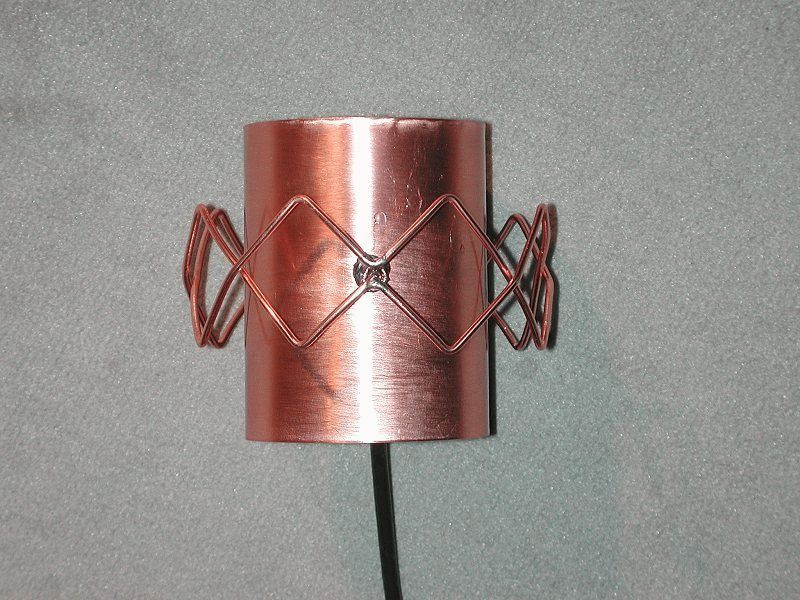
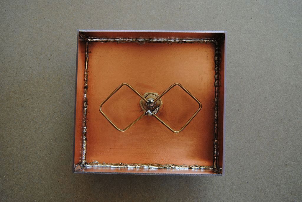
"Double Eight" is a continuation of Bi-Quad, the gain of which is 2 dB higher, i.e. is approximately 12 dB. During construction, pay attention to the fact that the copper wires do not touch at the intersection points. After construction, it is advisable to varnish the “double eight” to avoid oxidation/corrosion. The two photographs below demonstrate how important it is to maintain a distance of 15 mm between the reflector and the copper wire:


In order to avoid questions (there were in the first post), let's consider building an antenna with a circular diagram, in this case something around 270°.

First, from a copper plate (or other sheet metal/material), you need to bend a pipe with a diameter of 70 mm and a height of approx. 100 mm. Then bend a straight 6-element Quad from copper wire and, using, for example, a bottle, give it a corresponding, curved shape. I repeat for those who are not reading very carefully: the distance from the copper wire to the reflector in a circle should be 15 mm! It is important that the crossing wires do not touch each other!

Of course, this is not the only correct option for building such an antenna. The antenna with a circular diagram can be made larger,


In this case, signal loss in the antenna cable will be minimized.


Ideally it should look a little different, something like this:

but this is not so important, the main thing is that you can repeat the dimensions by printing. For those bending the “double eight” - the outer squares are not used. Those who do not have a printer can use the following drawing to make a frame: the dimensions are for a wire with a diameter of 2.5 mm

"Triple Eight" is another continuation of the "double eight", the gain coefficient of the "triple eight" can be 14 dB or a little more. This is what a colored “triple eight” looks like, in general, not bad:


For beginners! Please note that the stands supporting the antenna at a distance of 15 mm from the reflector must be made of dielectric material!
The “double eight” and the antenna with a pie diagram discussed above can be mounted together in one housing:


From another.

The antenna is closed. To make the protective housing, a piece of plastic pipe with a diameter of 125 mm, which is used in plumbing, was used; the lid is made of 2 cm plastic. The top fastening nut is made of plastic. Can be painted any color.


Manufacturing.
First of all, you need to make a reflector - this is a metal sheet 450x350 mm (the back of the antenna). It serves to reflect and transmit wifi waves to vibrators and also serves as the body of the antenna itself.
To do this, take a fairly thick sheet of iron. For example, a housing from an old washing machine or a baking tray will do the job. We cut out the required size with a grinder and clean it from rust. see photo 1 on the right
Let's put it aside For now, put the reflector blank aside and let’s start manufacturing vibrators, which will be located on a one-sided 1.5mm fiberglass laminate. To do this, you need to purchase a vinyl vibrator stencil with a self-adhesive mounting film. Such things are made in plotter cutting workshops according to the provided drawing.
Download drawing Delta Ds 2400-21. Copy to a USB flash drive. At a plotter cutting company, explain to the manager what the actual dimensions of the drawing parts should be!
Before gluing the stencil, remove small scratches and polish the copper surface of the fiberglass laminate using a scratch pad and GOI paste. Degrease the surface with a solvent (acetone)! Carefully transfer the stencil onto the copper surface of the fiberglass laminate. Let's start etching the antenna circuit board.
Pour hot water in a container of suitable size, add copper sulfate and table salt in a ratio of 1:3, mix thoroughly and lower the fiberglass glass down with copper. To prevent the board from sinking, first stick the foam on the opposite side using double-sided tape. Wait until the excess copper is completely dissolved. see photo 2 on the left.
When the process is finished, rinse the fiberglass with clean water and remove the vinyl from the vibrators and tracks. Make a hole for the contact of the N-235 TGT connector and tin. To protect from the external environment and from oxidation, cover the side of the antenna with vibrators with insulating varnish!
Place fiberglass on the reflector, make a mark and drill a hole for the n-type connector. Also make holes for external wifi antenna mounting kit, see photo 3 on the right.
Next we need to connect the reflector and the fiberglass board together. The gap between the reflector and the vibrators should be 9mm!
Here's what we'll do - glue 6mm pieces of laminate flooring to the reflector with a THIN layer of glue. Before this, place them evenly on fiberglass using double-sided tape, see photo 4 on the left.
Laminate 6 mm + fiberglass 1.5 mm + glue 1.5 mm = gap 9 mm.
Now we install it in its place and tightly tighten the N-235 TGT connector. After the glue has dried, peel off the fiberglass (held on with double-sided tape) from the reflector. We cover the laminate and the connector with masking tape, and paint the reflector on both sides with metal paint for outdoor use. The reflector is almost ready, we attach the external antenna mounting structure.
Next, apply a thin layer of “moment” glue to the laminate and connect the reflector with fiberglass laminate. Having inserted the contact of the n-type connector into the hole, solder its tip to the copper track of the vibrators. See photo 5 on the right.
In this example, a protective cover for the antenna is not provided. Instead, a hybrid adhesive-sealant “Soudal Fix All Crystal” is used and applied along the perimeter between the reflector and fiberglass, See photo 6 on the left. Then the front part of the wi-fi antenna is covered with three layers of white acrylic paint. First check the paint to see if it will shield your antenna. Paint a piece of thick paper and when the paint is completely dry, cover the front side of the wi-fi antenna. If the signal does not change, feel free to use this paint. See photo 7 on the right.
Let's check this product in action.
Here are the results of testing a DIY Wi-Fi antenna:
In order to connect the antenna, we need an external USB wifi adapter. This example uses "alfa awus036h 1000mw - Taiwan".
First, let's connect the adapter, without an antenna, and see what it shows us, and whether it even works? As it turned out, alfa found three points. We will focus on the connected point -66 dBm. For half an hour the signal hardly changed, and this was without any antenna. See photo 8 on the left.
Now, without changing the location, let’s check our homemade Wi-Fi antenna by pointing it towards the router. As you can see, the result is dramatically different for the better. See photo 9 on the right. The signal of the connected point has improved from -66 dBm to -45 dBm. Three more points were discovered.
66-45=21.
It turns out that the antenna gain is 21 dB.


