Program for testing electrical circuits in Russian. How to draw an electrical circuit on a computer - an overview of programs. Qucs - open-source CAD software for modeling electronic circuits
10 Best Free Online Circuit Simulators
List free programs electronic circuit simulation online is very useful for you. These circuit simulators that I offer do not need to be downloaded on a computer and can be run directly from the website.
1. EasyEDA electronic circuit design, circuit simulation and PCB design:
EasyEDA is an amazing free online circuit simulator which is very suitable for those who love electronic circuit. The EasyEDA team strives to do complex program design on the web platform for several years and now the tool is becoming amazing for the users. Software environment allows you to design the circuit yourself. Check the operation through the circuit simulator. When you make sure the circuit function is good, you will create the PCB with the same software. There are over 70,000+ charts available in their web databases along with 15,000+ Pspice library programs. On the site you can find and use many projects and electronic circuits, made by others, because they are public and open hardware. It has some pretty impressive import (and export) options. For example, you can import files into Eagle, Kikad, LTspice and Altium designer, and export files as .PNG or .SVG. There are many examples on the site and useful programs training that allows people to easily manage.
2. Circuit Sims: This was one of the first web based circuit emulators with open source I tested it a few years ago. The developer failed to improve the quality and increase the graphical user interface.
3. DcAcLab has visual and attractive plots, but is limited to circuit simulation. This is certain great program for learning, very easy to use. This makes you see the components as they are made. This will not allow you to design the circuit, but will only allow you to practice.
4. EveryCircuit is an online electronics emulator with well-made graphics. When you enter online program, and it will ask you to create a free account so you can save your designs and have a limited area to draw your diagram. To use it without restrictions, it requires an annual fee of $10. It can be downloaded and used on Android platforms and iTunes. The components have limited ability simulate with small minimum parameters. Very easy to use, it has a great system electronic design. It allows you to include (embed) simulations in your web pages.
5. DoCircuits: Although it leaves people with a first impression of confusion about the site, but it gives many examples of how the program works, you can see yourself in the video "will start in five minutes." Measurements of electronic circuit parameters will be demonstrated with realistic virtual instruments.
6.PartSim electronic simulator schemes online. He was capable of modeling. You can draw electrical circuits and test them. He's still new simulator, so there are several components to make simulations to choose from.
7. 123D Circuits Active program developed by AutoDesk, it allows you to create a circuit, you can see it on a breadboard, use the Arduino platform, simulate an electronic circuit and finally create a PCB. The components will be demonstrated in 3D in their actual form. You can program Arduino directly from this simulation program, (it) is really impressive.
8. TinaCloud This modeling program has advanced features. It allows you to simulate, in addition to conventional mixed-signal and microprocessor circuits, VHDL, SMPS electrical supply and radio frequency circuits. Calculations for electronic modeling are performed directly on the company’s server and allow excellent speed modeling
Electrical schematic software is a tool used by engineers to create electronic circuits for the purpose of designing and testing products during the design, manufacturing, and operational stages. Accurate display of parameters is done using a scale. Each element has its own designation in the form of symbols corresponding to GOST.
Software for electrical circuits: why do I need it?
Using electrical diagramming software, you can create precise drawings and then save them to in electronic format or print.
IMPORTANT! Almost all programs for drawing diagrams have ready-made elements in the library, so you don’t have to draw them manually.
Such programs can be paid or free. The former are characterized by great functionality, their capabilities are much wider. There are even whole automated systems CAD designs that are successfully used by engineers around the world. With the use of programs for drawing diagrams, the work is not only fully automated, but also extremely accurate.
Free programs are inferior in price functionality paid software, but with their help you can implement projects of initial and medium complexity.
The software allows you to simplify your work and make it more efficient. We have prepared a list popular programs to create circuits used by professionals around the world. But first, let's figure out what schemes are and what types they come in.
Programs: what schemes are they intended for?
The diagram is a design document graphic type. It displays the components of the device and the connections between them in the form of symbols.
The diagrams are part of the design documentation set. They contain the data necessary for the design, production, assembly, regulation, and use of the device.
When are diagrams needed?
- Design process. They allow you to determine the structure of the product being developed.
- Production process. They provide an opportunity to demonstrate the design. Based on them, it is being developed technological process, method of installation and control.
- Operation process. Using the diagrams, you can determine the cause of the breakdown, correct repair and maintenance.
Types of schemes according to GOST:
- kinematic;
- gas;
- energy;
- pneumatic;
- hydraulic;
- electrical;
- combined;
- optical;
- divisions;
- vacuum
Which program is better to work in?
Exists great amount paid and free programs for developing electrical drawings. The functionality is the same for all, with the exception of advanced features for paid ones.
Visio
QElectro Tech
sPlan
Visio
Pros of QElectro Tech
- export in png, jpg, bmp or svg format;
- checking the functionality of electrical circuits;
- It is easy to create electrical wiring diagrams, thanks to the presence of an extensive library; completely in Russian.
Cons of QElectro Tech
- limited functionality;
- creating a network diagram of initial and medium complexity.
- Stages of work
Simple interface. A collection of figures for assembling electrical circuits is located on the left in the main window. IN right side there is a work area.
- Create a new document.
- Drag with the mouse to work area required amount elements to create and simulate the desired result.
- Connect the parts together. Connections are automatically converted to horizontal and vertical lines.
- Save the file with the qet extension.
There is a construction function own elements and preservation in the library. The shapes can be used in other projects. Software in Russian. The program is suitable for Linux and Windows.
sPlan
A program for building electronic and electrical circuits, drawing boards. When moving elements from the library, they can be snapped to a coordinate grid. The software is simple, but allows you to create drawings and drawings of varying complexity.
Photo 3 - Process of drawing up a diagram in sPlan
sPlan's mission is to design and develop electronic circuit diagrams. To simplify the work, the developer has provided an extensive library with geometric designation templates electronic elements. There is a function for creating elements and saving them in the library.
Stages of work:
- Create a new document.
- Drag the required elements from the library of elements. Shapes can be grouped, rotated, copied, cut, pasted, and deleted.
- Save.
EDA (Electronic Design Automation) - software for development and testing of electronic equipment. In the very in a general sense EDA includes Sprint Layout, which is so widespread in the Russian-speaking environment. More well-known (and more complete products) include Eagle, DipTrace and Proteus. But they all have one small drawback - they are paid. Someone might object: the same Eagle supposedly has free version, albeit somewhat limited. However, these restrictions sometimes become not so much a hindrance as an irritation, such as the inability to position elements off the board, which makes it difficult to redistribute already located parts. Therefore, let's talk about KiCad - until recently little-known, but now gaining popularity software, somewhat burdened with cross-platform, but at the same time actively developing (the latest one is on this moment stable version published in October 2014). In a couple of articles I will try to talk about the basic techniques and pitfalls working with KiСad. As an example, let's take a simple Step-Up converter circuit on.
KiCad Program Overview
The main KiCad window is divided into several blocks
- The main menu where you can create or open a project, archive it in zip or unpack it, specify text editor for viewing files (for example, a list of items) and an application for PDF viewer, select a language (currently there are 19 languages in the list, including Russian), read the help and copy to the clipboard full information about the installed version.
- The second block contains (from left to right): creating a new project; creating a project from a template (there are no templates yet, but you can create them yourself; such templates will be added to the “Custom” list); opening an existing project; saving all files, be it a circuit diagram or a printed circuit board; archiving the current project in zip; updating the list of project files.
- The third block contains the actual list of files - everything that has a name that matches the name of the project is displayed here.
- The buttons of the fourth block allow you to navigate between the following editors: Eeschema - editor of electrical circuit diagrams of the device; CvPcb - comparison of component seats (in other words, selection of the body of a particular part); Pcbnew - printed circuit board editor; Gerbview - Gerber file viewer; Bitmap2Component - used to create logo images or to create components from existing images. Calculator - contains utilities such as a stabilizer calculator, tables of recommended track thicknesses for printed circuit boards, tables color coding resistors, etc.
- Finally, in last block the actions we performed with the current project are displayed (what was opened, what was saved, etc.).
The creation of any device begins with the creation of a new project. Therefore, click on the button “ Start a new project».

Select the folder for the future project, write its name, click “ Save", regardless of the style of my windows, in Windows they will be familiar and familiar.

The project name will appear in the left column and we can finally click on the button Eeschema. An editor like this will open...
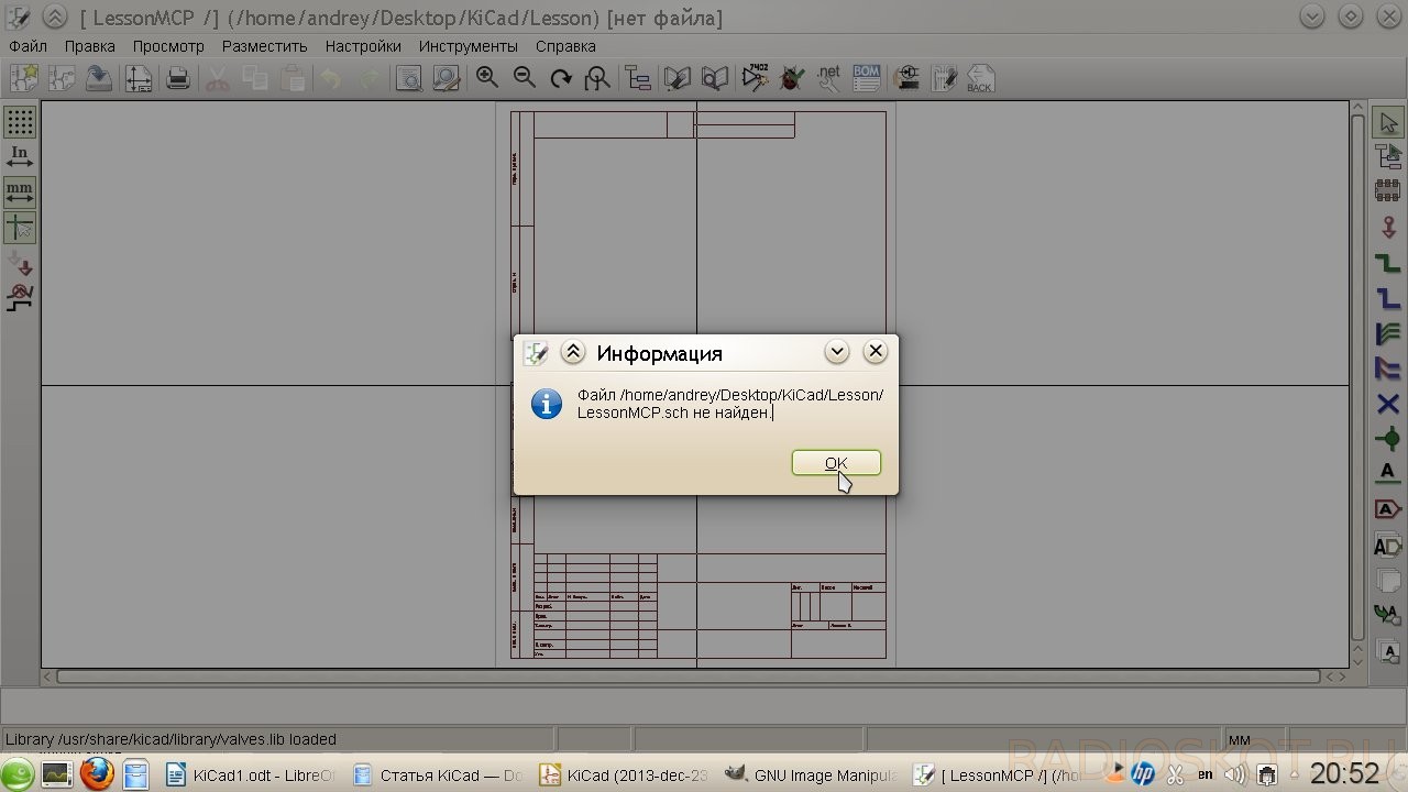
And KiCad will happily inform us that a certain file is missing. Everything is fine, it just reminds us that we haven't saved the schema yet, so it was created Blank sheet. In general, KiCad's twists and turns of logic are sometimes amazing. What’s even funnier is that this miracle is supported not by just anyone, but by CERN themselves.
But we digress, let's press OK. In the window that opens, we see the sheet on which our future diagram will be located. Actually, it can be located outside of this sheet, but these parts simply will not be printed. Around the workspace we see a bunch of different buttons; there is no point in explaining the purpose of each of them, because a hint pops up on each of them when you hover (naturally, in Russian). It is worth identifying only the main ones:

Don't be alarmed, everything is not as difficult as it seems at first. As a circuit, as mentioned above, I chose a converter based on MCP34063, also known as MC34063. The diagram is taken from the datasheet:

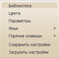
First of all, let’s look at the menu item “ Settings", where in addition to setting colors, parameters appearance(mesh pitch, connection thickness, etc.) we are interested in the item “ Library" Libraries in KiCad, like in Eagle, contain components used in constructing a circuit. Let's make sure that the files supplied with KiCad are connected and present in the list.

Other libraries can be easily Googled and added via the " Add"(which is quite logical). I also advise you to download component libraries converted from Eagle. However, you should not include all the files at once - this can lead not only to slower loading of the project, but also to annoying messages about duplication of components in libraries. Having dealt with the little things, click on the button “ Place a component" in the right panel (or the item " Component" on the menu " Post") and click anywhere on the sheet.


In the window that appears, write in the “Name” field: 34063 - here, unlike Eagle, you do not need to know the exact name of the component, just a part of it is enough.

You can also select a component from the list (button " List of all") or by selecting a suitable symbol (" Select by browsing"). Click OK. If the entered designation appears in several components, we are prompted to select the one we need.

Place the symbol on the sheet.

Attention, rake! KiCad inherited the good tradition of hotkeys from Unix systems. To move a positioned component, it is not enough to simply click on it. You should move the cursor over the component and press Latin [M] (from the English Move) on the keyboard, or right-click on the component and select context menu corresponding item. In the same way, turn with the [R] key and drag (that is, move without breaking away from the chains) with the [G] key. We add a component through the combination, and a conductor through it. The same thing can be done through the context menu. Hotkeys may seem awkward, but in fact most of them are intuitive to a user familiar with English words. In addition, by memorizing a couple of dozen combinations, you can significantly speed up your work. So don’t be lazy and read the certificate, fortunately it has been completely translated into Russian.
Following the microcircuit, we add the remaining components to the sheet. To add passive elements, just write their more or less generally accepted designations (R, C, CP, etc.) in the “Name” field. Once selected, components remain in the “History List” field for quick addition.

To complete adding components, press the key or select the item “ Set aside the tool" To connect the circuits we use “ Place Explorer».

It turns out something like this:

If the connection of conductors seems inconvenient (or if the circuit is divided into separate blocks), then it makes sense to use labels. They tie separate areas chains, just like the names in Eagle. KiCad has several types of labels (local, global and hierarchical). Global and hierarchical are used when the blocks of the diagram are located on several sheets and they need to be linked together. The most primitive one is enough for us, so we choose “ Place chain name(local label)".

Click on the desired connection and write the name of the label. At the same time, we select the orientation of the mark - where its connecting point will be located.

Attention, rake! KiCad does not permanently tie the tag to the connection like Eagle does. Once created, a tag can be moved like any other component, but in order for it to be “picked up” by a circuit, its connecting point must align with a connection on the circuit or component.

Having placed the necessary marks, we get the following picture:

Now let's add ground and power circuits. They belong to the tool " Place power port»

We write in the search bar “ GND».

Or choose required component through the button " List of all»

Having placed the land, we do the same with Vin, selecting the appropriate component. It will have to be connected to a separate conductor. To do this, take the tool “ Place Explorer", click on the desired section of the circuit and pull the conductor to the side. In order to end it not at the connection point, but in an arbitrary place on the sheet, double-click the mouse.

We place the power supply for our circuit. At the output it is enough to simply place a label like “ Vout».

Now let's designate the components and indicate their values. This is done quite simply: you need to hover the cursor over the component and press the [ key V] to assign a denomination and the [ U] to indicate the serial number. However, numbers can also be assigned automatically. To do this, press the button “ Label the components on the diagram»

In the window that appears, configure the notation parameters (you can leave it as is). If parts of the components have already been assigned serial numbers, then you can either continue the current numbering or start it again by first clicking on the button Reset designations».

Having finished with the preparation, click “Design components” and agree with the proposal to give serial numbers to everything. Let's arrange the denominations. Hover the cursor and press [ V]. If several components are in focus, KiCad displays a small menu asking us to specify which component we want to edit.


Finally, check the correctness of the diagram by clicking the “ Perform check...»

In the window that appears, you can configure the verification parameters - the rules for connections between pins (what is considered an error, what is a warning) on the “Parameters” tab.

On the “ERC” tab, click “ ERC test"... and we see error messages.

In this case, green arrow markers will appear on the diagram next to the problem areas. Selecting a line from the list of errors in the ERC window will take us to the corresponding marker. So what is our problem? Here's the thing: it's not enough for KiCad to just put a power port on the circuit; it also needs to indicate that the power port added through the power port is just a power port, and not something else. The apotheosis of crutches, in my opinion, but completely solvable. You just need to pick up the tool again " Place power port» and select the component in the list of ports PWR_FLAG.

The following symbol will appear on the diagram:

PWR_FLAG is displayed only on the diagram and is needed solely to successfully verify its correctness. We connect it to the positive power supply and the GND circuit. We run the ERC test again - there are no more errors.
Attention, rake! When microcircuits with pins that are not connected anywhere are used, the ERC test will swear in their direction. To prevent this from happening, the “Not Connected” flag should be set on all unused pins.
As a result, we ended up with this diagram:

To print it, click on top panel button " Printing the diagram", or select this item in the menu " File».

Attention, rake! Linux users may encounter a problem when a blank sheet is printed instead of a diagram. This is due to incorrect operation wxWidgets with printers.
- a) update wxWidgets to version 3.0;
- b) use the schema export to an accessible graphic format either in PDF file and then print it.
It’s not entirely clear what motivated the KiCad developers, but the familiar export is located in the “ Draw».

Here we select the format, configure color mode and image quality (default line thickness), choose whether we need to export the sheet frame along with the diagram. That's probably all you need to know to get started with EESchema. And next time we will talk about the intricacies and creation of new components for libraries. Author of the review - Vetinari.
Discuss the article SOFTWARE FOR DEVELOPING AND TESTING CIRCUITS
January 15, 2015 at 5:54 pmQucs - open-source CAD for electronic circuit modeling
- CAD/CAM
There aren't that many open-source CAD programs out there at the moment. However, among electronic CAD (EDA) there are some very worthy products. This post will be dedicated to the open-source electronic circuit simulator. source code. Qucs is written in C++ using the Qt4 framework. Qucs is cross-platform and released for Linux, Windows and MacOS.
The development of this CAD system began in 2004 by the Germans Michael Margraf and Stefan Jahn (currently not active). Qucs is currently being developed by an international team, which includes me. The project leaders are Frans Schreuder and Guilherme Torri. Below the cut we will talk about key capabilities our circuit simulator, its advantages and disadvantages compared to analogues.
The main window of the program is shown in the screenshot. There a resonant amplifier is modeled on field effect transistor and oscillograms of the voltage at the input and output and also the frequency response were obtained.
As you can see, the interface is intuitive. The central part of the window is occupied by the actual simulated circuit. Components are placed on the diagram by dragging and dropping from the left side of the window. Modeling views and equations are also special components. The principles of editing circuits are described in more detail in the program documentation.
The Qucs schema file format is XML based and comes with documentation. Therefore Qucs schema can be easily generated third party programs. This allows you to create circuit synthesis software that is an extension of Qucs. Proprietary software typically uses binary formats.
Let's list the main components available in Qucs:
- Passive RCL components
- Diodes
- Bipolar transistors
- Field effect transistors (JFET, MOSFET, MESFET and microwave transistors)
- Ideal op amps
- Coaxial and microstrip lines
- Library components: transistors, diodes and microcircuits
- File components: subcircuits, spice subcircuits, Verilog components
The component library uses a proprietary XML-based format. But you can import existing component libraries based on Spice (listed in the datasheets for electronic components).
Supported the following types modeling:
- DC Operating Point Simulation
- Frequency Domain Modeling on AC
- Time Domain Transient Simulation
- S-parameter modeling
- Parametric analysis
Simulation results can be exported to Octave/Matlab and data post-processing can be performed there.
Qucs is based on a newly developed circuit simulation engine. A distinctive feature of this engine is the built-in ability to simulate S-parameters and SWR, which is important for analyzing RF circuits. Qucs can convert S-parameters into Y- and Z-parameters.
The screenshots show an example of modeling the S-parameters of a wideband high-frequency amplifier.


So, distinctive feature Qucs is the ability to analyze complex frequency characteristics(CCH), construction of graphs on the complex plane and Smith diagrams, analysis of complex resistances and S-parameters. These capabilities are not available in the proprietary MicroCAP and MultiSim systems, and here Qucs even outperforms commercial software and achieves results unattainable by Spice-based circuit simulators.
The disadvantage of Qucs is the small number of library components. But this drawback is not an obstacle to use, since Qucs is compatible with the Spice format in which the models are presented electronic components in datasheets. The modeler is also slower than similar Spice-compatible modelers (such as MicroCAP (proprietary) or Ngspice (open-source)).
We are currently working on the ability to provide the user with a choice of engine for circuit simulation. It will be possible to use the built-in Qucs engine, Ngspice (a Spice-compatible console modeler similar to PSpice) or Xyce (a modeler that supports parallel computing via OpenMPI)
Now let’s look at the list of innovations in the recent release of Qucs 0.0.18 promising areas in Qucs development:
- Improved Verilog compatibility
- Porting of the interface to Qt4 continues
- Implemented a list of recent open documents in the main menu.
- Implemented export of graphs and diagrams to raster and vector formats: PNG, JPEG, PDF, EPS, SVG, PDF+LaTeX. This function is useful when preparing articles and reports containing simulation results
- Ability to open a schematic document from future version programs.
- Fixed bugs related to the modeler freezing under certain conditions.
- A system for synthesizing active filters for Qucs is being developed (expected in version 0.0.19)
- Development of interface with other open-source engines for modeling electronic circuits is underway (
A simulator with a user-friendly interface for the development and calculation of electronic circuits and circuits.
Quite Universal Circuit Simulator software is an editor with graphical interface with a complex technical capabilities for designing circuits. For driving complex circuits The ability to expand subcircuits and form blocks is included. The software includes a built-in text editor, applications for calculating filters and matched circuits, line calculators and attenuator synthesis. The drawing can be framed with a frame and a standard stamp.
Qucs includes a wide base of modern components, divided into categories: discrete (resistors, capacitors, etc.), nonlinear (transistors and diodes), digital (basic digital devices and logic gates) and others (sources, meters). Of particular interest are the figures and diagrams.

Qucs can be configured for many languages, including Russian.
The program runs on Mac OS, Linux and Windows XP, Vista, 7 and 8.
For free.
Simulator “The Beginning of Electronics”
There is very interesting program, which is a simple simulator for demonstrating the operation of electrical circuits and operation measuring instruments. Its convenience lies not only in its clarity, but also in the fact that the interface is in Russian. It allows you to model very simple circuit diagrams. The program is called “Beginnings of Electronics”. Link to it at the bottom of the page, video of Mikhail Mayorov’s channel.
This Chinese store has everything for radio amateurs and DIYers.
The program works from Windows 98 to Windows 7. The interface looks like this.
 Below is a drawing printed circuit board, but for us the greatest interest is the socket with development board. At the top there are control buttons: load the circuit from a file, save the circuit, clean the breadboard, get a multimeter, get an oscilloscope, show parameters of parts, condition of parts, reference book, (concepts about electricity are briefly outlined), a small list laboratory work for carrying them out independently, instructions for using the simulator, information about the authors, exiting the program.
The video shows how the circuit simulator works.
What can you build on a circuit simulator?
On this a simple simulator you can collect quite a lot of interesting things. First, let's model a regular flashlight. To do this, we need a light bulb, two batteries and, naturally, all this will need to be connected with jumpers. Well, what is a flashlight without a switch and a light bulb?
Double-click to open the battery parameters window. On the tab that appears we see the voltage, internal resistance, showing its power, minipolarity. IN in this case The battery lasts forever.
When the circuit is assembled, we press the switch twice and for some reason the light bulb burns out. Why? The total voltage of series-connected batteries is 3 volts. The default light bulb was 2.5 volts, which is why it burned out. We install a 3-volt light bulb and turn it on again. The light bulb glows happily.
Now let's take a voltmeter. His “palms” light up. These are measuring probes. Let's move the probes to the light bulb and take a measurement DC voltage with a limit of 20 Volts. The monitor shows 2.97 volts. Now let's try to measure the current. To do this, take a second multimeter. The device connected to the circuit showed almost 50 milliamps.
Almost like a real multimeter, you can measure many parameters. There is also an oscilloscope in the simulator, whose beam brightness can even be adjusted. In addition, there is a rheostat, you can move the engine. There is a variable capacitor, shunts, a heating stove, resistors, fuses and more. Unfortunately, there are no transistors in this simulator.


