Breadboards. Breadboard - electronic construction kit for everyone
Development boards can be assembled for any device. They are popular among beginner electronics engineers and experienced craftsmen. They are assembled with and without soldering. The former are durable and can be used as the main board, while the latter are more convenient to assemble due to the elimination of soldering work.
To begin production of any product, you need to make a mock-up of it, and then, after assessing the performance of the product and its other parameters, begin production of the series. In this case, you save money and time. But prototypes are made not only in production, they are also widely used in electronics and, first of all, this is associated with the production of breadboards.
Let's say you're about to make a new electronic device. Previously, a prototyping board prototype looked like a rectangle made of cardboard, in which holes were made and radio elements interconnected were inserted there, and then its operation was checked. If the device functioned normally, then production of the main board began using appropriate materials. Now the task is somewhat simplified - breadboards with already prepared holes and tracks are actively sold on the market, which can be found in specialized stores, for example, here at http://makerplus.ru/, where you can choose the appropriate option.
What types of breadboards are there?
Breadboards are made without soldering and with soldering. The solderless design consists of a plastic case with numerous holes with contact connectors. Parts are mounted in them. The holes are designed for wires with a diameter of 0.7 mm. The distance between them is 2.54 mm, which is enough to install a transistor and other elements.
The power paths are indicated by blue and red lines. The number of connector points can vary from 100 to 2500 pieces. The principle of working with such a board is simple. You mount electronic elements into the required holes and connect them with ordinary wires, or buy specially prepared jumper wires. If the circuit is assembled incorrectly, then you disassemble it and reassemble it.
Breadboard with soldering
This board differs from the option discussed above in that the elements installed in the case can be soldered. In this case, you can use it not only as a mock-up, but also as a real product. True, then the board will be somewhat larger. In addition, soldered structures have a lower price.
Boards with soldering, which, by the way, can be purchased on the online store page http://makerplus.ru/category/breadboard, have holes for wires with a diameter of up to 0.9 mm and are located in increments of one inch (2.54 mm). On one side of the structure there are straight insulated foil lines, and on the other side radio elements and jumpers are installed.
- Immediately cut the board to the required size. For this, ordinary scissors, a cutter, or a hacksaw are suitable. You can even just break it along the holes, but then clean the edges.
- If you are not going to use the board right now, then do not touch the areas with foil with your hands again. Hands may be wet, which will lead to surface corrosion and poor contact.
- If oxides or dirt occur, clean them with fine sandpaper or a regular eraser.
- Radio elements are installed on the side where there are no foil strips. The leads are inserted into the holes and sealed on the reverse side.
- The blue color of the conductive paths indicates the “minus” of the circuit, the red “plus”, and green is used at your discretion. The tracks are marked on the same side where the foil is located.
- The most important positioning of parts occurs in a vertical position, since in this case an error will lead to an incorrectly assembled chain.
Please note that both types of breadboards may have slots on the sides. This is necessary for those who assemble a large device consisting of several modules. The grooves allow you to assemble one large board from several small ones.
Hello everyone. Today we will talk about a breadboard. Radio amateurs will understand without any questions, since almost everyone went through crafts on breadboards at the beginning of their development. For the rest, a little more detail. A development board is needed for temporary installation of radio components when debugging electronic circuits and solving problems that arise during the manufacturing stage of the device.
In the days of my youth and total shortages, breadboards were made independently from a piece of foil getinax or fiberglass, drawing out the copper coating into a square with a cutter, so that there would be many pads to which contacts of radio components could be soldered according to the diagram. This was justified, since making the board yourself was quite labor-intensive. It even happened that homemade products remained in their original form on the breadboard, since no one inside the case could see how clumsily everything was made, but the circuit worked and the original goal was achieved. Saving time and resources is obvious.
A homemade breadboard often looked like this: 
But time passed, progress did not stand still. As skills grew, the circuits became more complex, the number of pins and soldering points increased proportionally, and homemade breadboards (breadboards) no longer completely solved the problem. This is where industrial breadboards began to appear, or rather they existed before, but were not available to everyone. And if for the guys from the radio club at first making a radio receiver or color music was an achievement, then later circuits with digital logic became even more difficult to implement. After all, we had to drill a lot of small holes and paint the conductors with nail polish, and finally etch them in copper sulfate. And if mistakes were made during manufacturing, then the appearance of the board quickly deteriorated to something terrible.
This is also a development board, but industrially manufactured: 
In the abundance of wires one can guess some kind of Spectrum clone.
At the moment, electronics engineers have access to various modern technologies for manufacturing boards, including orders of small series from factories at a relatively low price. But breadboards in any case occupy their niche and sooner or later they have to be used.
Order and delivery
In general, I didn’t really need a breadboard (hereinafter referred to as a breadboard), since I do not manufacture electronics professionally and exclusively for myself. But when I saw it on sale by chance, I decided to order it. The board was ordered in November last year, it arrived in a simple package without bubbles, in about a month. There was nothing inside except the board itself. There was no damage given the fragility of the getinax.
It looks like this: 

The color of copper foil is pleasant, almost natural. The breadboard tracks are coated with a protective compound resembling a weak solution of rosin in alcohol. At least when soldering, the amount of smoke is minimal and there are no traces of burnt rosin.
The dimensions are stated to be 9x15 cm, in fact they are, the thickness is 1 mm, which in my opinion is not enough considering the properties of the material. The foil layer has a thickness of approximately 20 microns. 
last date of verification =)

My micrometer hasn’t been checked for 31 years, so the readings are conditional. In production, the minimum foil thickness is 18 microns, which corresponds to the cheapest option.
There are 30 rows of 48 holes on the board, which ultimately gives 1440. The latter are squeezed out during the formation of the board. Drilling such a number of holes is not economically feasible. Hole diameter 1 mm. Unfortunately, parts with pins of 0.7 and 0.8 mm have to be fixed during soldering, otherwise they tend to fall out.

Octagon-shaped contact pads size 2 mm. There is no metallization in the holes. Since the life of the board is minimal and the price with metallization will be unreasonably high.

Getinax breadboard base
Getinax is an electrically insulating layered pressed material having a paper base impregnated with phenolic or epoxy resin.
Mainly used as the basis for printed circuit board blanks. The material has low mechanical strength, is easy to process and has a relatively low cost. It is widely used for the cheap production of circuit boards in low-voltage household equipment, since in a heated state it can be stamped, resulting in a circuit board of any shape along with all the holes.
I immediately remember boards from TVs. Due to their low resistance to mechanical and thermal loads, boards based on getinax are less maintainable and in some cases have even been sources of fire...
Trial application:
These are the ingredients I use
For soldering 
Solder with rosin inside, natural rosin, soldering iron 25 W, tip temperature approximately 330-350 degrees without adjustment.
And for cutting, a defort engraver + a set of Chinese cutters 

The cutters are of course terrible in terms of quality, I bought them for the New Year from JD, I couldn’t resist.
There was a reason to assemble a power supply for a +5V +12V-12V signal generator. At first I wanted to remake the mobile phone charger by home-winding the windings, but I couldn’t find one with a normal gap for the wires. Therefore, the choice fell on the breadboard.
A transformer of an unknown type played a cruel joke on me - since the pitch of the holes on the board is 2.54 mm - inch, I had to re-drill the holes in place. The board is drilled easily, and even a blunt drill does not particularly slow down the drilling process, although it knocks out pieces of the board from the back side.
Several photos of the finished power supply. This is exactly the case when I decided not to make the board.


The 7912 stabilizer played a cruel joke on me - the pinout does not match the 7812. Because of this, I burned the KTS407 diode bridge. Having realized my mistake, I re-soldered. While re-soldering, one contact pad fell off. So the quality of the board is to mock it up a couple of times and switch to a new one.
The contact pads were tinned with virtually no rosin, just the amount that was in the solder.

No matter how much I tried, I couldn’t make a drop on the contact; the solder always trails behind the soldering iron. Perhaps the temperature is not enough.
I'm trying to cut it off


It seems that the speed is high, but the getinax crumbles. However, the dust is not as harmful as that of fiberglass.
Why did I buy this particular breadboard and not more advanced ones - for rare use and I wouldn’t mind throwing it away. I practically don’t use metallization. A solderless breadboard was also purchased, but is currently unused. Compared to the one under review, it has a disadvantage - it requires leads of the required length and molded ones. And since I have huge stocks of old and used parts (I scold myself to constantly throw everything away), soldering is the only correct option.
Conclusions: budget layout. If you don't have a couple in stock, you can have them.
Where is the cat?
I'm planning to buy +13 Add to favorites I liked the review +24 +39Often, in order to quickly assemble a prototype of some electronic circuit on the table, it is convenient to use a breadboard, which allows you to do without soldering. And only then, when you are convinced that your circuit is working, can you bother creating a printed circuit board with soldering. For a person just starting to explore the world of electronics, it may not be at all obvious to use a tool such as a breadboard or breadboard. Let's see what a development board is and how to work with it.
Instructions for working with a solderless breadboard (breedboard)
We will need:
- Breadboard, buy;
- connecting wires (I recommend this set);
- LED (can be purchased);
- a resistor with a resistance of 330 Ohms or close to it (an excellent set of resistors of all popular values);
- 9 volt Krona battery.
1 Description breadboard
There are many types of breadboards. They differ in the number of pins, number of buses, and configuration. But they are all arranged according to the same principle. A development board consists of a plastic base with many holes, usually spaced at a standard 2.54mm pitch. The legs of the output microcircuits are usually located with the same pitch. The holes are needed to insert the leads of radio elements or connecting wires into them. A typical view of a breadboard is shown in the figure.
Various types of breadboards
This type of board received its English name - breadboard ("board for bread") due to comparison with a board for slicing bread: it is suitable for quickly "cooking" simple circuits.
There are also breadboards for soldering. They differ in that they are usually made of fiberglass, and their metallized pads are well suited for soldering wires and lead radio elements to them. In this article we do not consider such boards.
2 Device breadboard
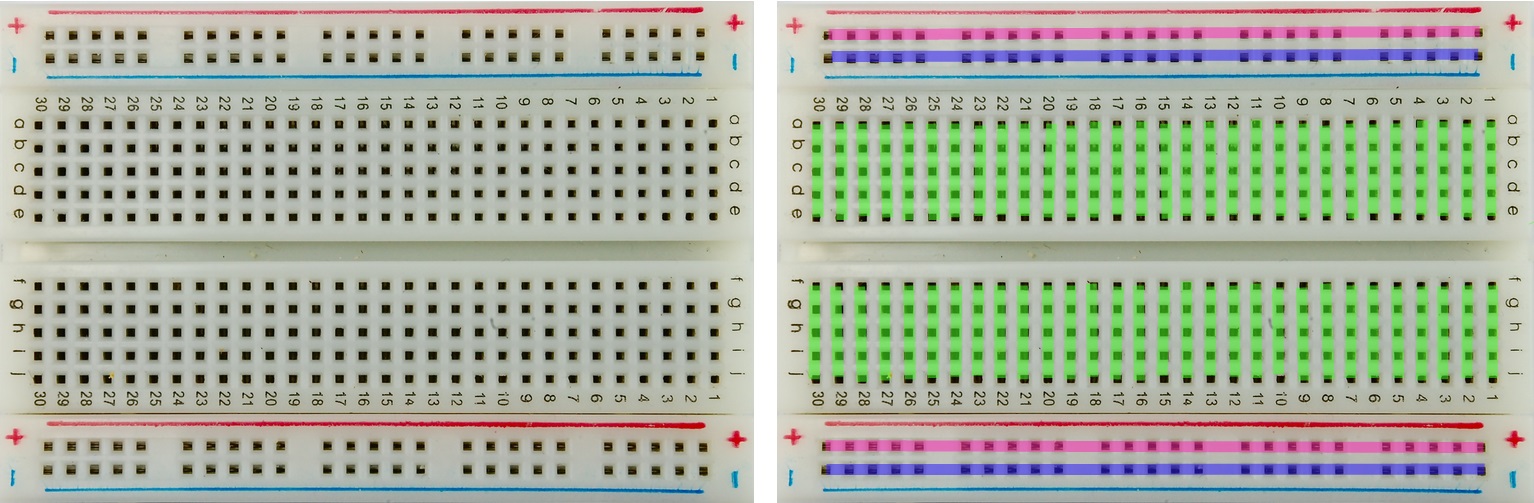
Let's see what's inside the breadboard. The figure on the left shows a general view of the board. On the right side of the figure, the conductor buses are indicated in color. Blue color is the “minus” of the circuit, red is the “plus”, green are conductors that you can use at your discretion to connect parts of the electrical circuit assembled on the breadboard. Note that the center holes are connected in parallel rows across the breadboard, not lengthwise. Unlike the power rails, which are located along the edge of the breadboard along its edges. As you can see, there are two pairs of power rails, which allows, if necessary, to supply two different voltages to the board, for example, 5 V and 3.3 V.
 Breadboard device
 The two groups of transverse conductors are separated by a wide groove. Thanks to this recess, microcircuits in DIP packages (cases with “legs”) can be placed on the breadboard. Like the picture below:

There are also radioelements for surface mounting (their “legs” during installation are not inserted into holes in the printed circuit board, but are soldered directly to its surface). They can be used with such a breadboard only with special adapters - clamping or soldering. Universal adapters are called “zero gain panels” or ZIF panels, using foreign terminology. Such adapters are most often for 8-pin microcircuits and for 16-pin microcircuits. An example of such elements and such an adapter is shown in the illustration.

The numbers and letters on the breadboard are needed so that you can more easily navigate the board and, if necessary, draw and label your circuit diagram. This can sometimes be useful when installing large circuits, especially if you are installing according to the description. Use them in much the same way as letters and numbers on a chessboard, for example: connect the resistor output to socket E-11, etc.
3 Assembling the circuit on a breadboard
To acquire the skill of working with a breadboard, let’s assemble a simple circuit, as shown in the figure. We connect the “plus” of the battery to the positive bus of the breadboard, the “minus” - to the negative bus. The bright red and black lines are the connecting wires, and the pale translucent ones are the connections provided by the breadboard, they are shown for clarity.
Breadboard (solderless circuit board) is one of the main tools for both those learning the basics of circuit design and professionals.
In this article you will get acquainted with where and how to use breadboard and what they are. After familiarizing yourself with the given basics, you will be able to assemble your own electrical circuit using a solderless breadboard.
Historical excursion
In the early 1960s, chip prototyping looked something like this:
Metal stands were installed on the platform, on which conductors were wound. The prototyping process was quite long and complex. But humanity does not stand still and a more elegant approach was invented: Carefree breadboards!
If you know that bread is translated as bread, and board is a board, then one of the associations that may arise when mentioning the word breadboard is a wooden stand on which bread is cut (as in the figure below). In principle, you are not far from the truth.

So where did this name come from - breadboard? Years ago, when electronic components were large and clunky, many DIYers in their garages assembled circuits using bread slicers (an example is shown in the picture below).

Gradually, electronic components became smaller and it was possible to reduce prototyping to the use of more or less standard conductors, connectors and microcircuits. The approach has changed somewhat, but the name has migrated.
Breadboard is a solderless circuit board. This is a great platform for developing prototypes or temporary circuits without the need for a soldering iron and all the hassle and time-consuming desoldering that comes with it.
Prototyping is the process of developing and testing a model of your future device. If you don't know how your device will behave under certain specified conditions, it is better to first create a prototype and test its performance.
Solderless circuit boards are used both for creating simple electrical circuits and for complex prototypes.
Another area of application for breadboards is testing new parts and components - for example, microcircuits (ICs).
As mentioned above, the electrical circuit you create may well change and this is the main advantage of using solderless circuit boards. For example, at any time you can include an additional LED in the circuit, which will respond to certain conditions in your circuit. The figure below shows an example of a circuit diagram for testing the functionality of the Atmega chip, which is used in Arduino Uno boards.

“Anatomy of solderless circuit boards”

The best way to explain exactly how a breadboard works is to figure out what the board looks like from the inside. Let's look at the example of a miniature board.
The picture below shows a breadboard with the base at the bottom removed. As you can see, the board has rows of metal plates installed on it.

Each metal plate looks like the figure below. That is, it is not just a plate, but a plate with clips that are hidden in the plastic part of the circuit board. It is into these clips that you connect your wires.

That is, as soon as you connect a conductor to one of the holes in a separate row, this contact will be simultaneously connected to the other contacts in a separate row.
Please note that there are five clips on one rail. This is the generally accepted standard. Most solderless circuit boards are implemented this way. That is, you can connect up to five components inclusive to a separate rail on the breadboard and they will be interconnected. But there are ten holes in a row on the board!? Why are we limited to five pins? You probably noticed that in the center There is a separate rail without pins on the circuit board? This rail isolates the plates from each other. We will discuss why this is done a little later. Now it is important to remember that the rails are isolated from each other and we are limited to five connected contacts, not ten.
The picture below shows an LED mounted on a solderless circuit board. Note that the two LED legs are mounted on insulated parallel rails. As a result, there will be no contact closure.

Let's now look at a large breadboard. On such boards, as a rule, two vertically located rails are provided. The so-called power rails.

These rails are similar in design to horizontal ones, but are connected to each other along the entire length. When developing a project, you often need power for many components. It is these rails that are used for power supply. They are usually marked with “+” and “-” and with two different colors - red and blue. As a rule, the rails are connected to each other to get the same power on both sides of the breadboard (see the figure below). By the way, there is no need to connect the plus specifically to the rail marked “+”, this is only a hint that will help you structure your project.

Center rail without contacts (for DIP chips)
A pinless center rail insulates the two sides of the solderless circuit board. In addition to insulation, this rail has a second important function. Most integrated circuits (ICs) are manufactured in standard sizes. In order for them to take up minimal space on the circuit board, a special form factor called Dual in-line Package, or DIP for short, is used.
For DIP microcircuits, the contacts are located on two sides and fit perfectly on two rails in the center of the breadboard. It is in this case that contact insulation is an excellent option, which allows you to route each contact of the microcircuit onto a separate rail with five contacts.
The figure below shows the installation of two DIP chips. Above is the LM358, below is the ATMega328 microcontroller, which is used in many Arduino boards.

Rows and Columns (horizontal and vertical rails)
You've probably noticed that solderless circuit boards have numbers and letters near the rows (horizontal rails) and columns (vertical rails). These markings are provided for convenience only. The prototypes of your devices very quickly become overgrown with additional components, and one error in the connection leads to the inoperability of the electrical circuit or even to the failure of individual components. It is much easier to connect a contact to a rail, which is marked with a number and a letter, than to count the contacts “by eye”.
In addition, many instructions also indicate the rail numbers, which makes assembling your circuit much easier. But do not forget that even if you use the instructions, the contact numbers on the breadboard do not have to match!
Pegs on breadboards
Some circuit boards are made on a separate stand on which special pegs are installed. These pegs are used to connect a power source to your breadboard. These breadboards are discussed in more detail below.
Other features
When you're designing an electrical circuit, you don't have to limit yourself to just one breadboard. Many circuit boards have special slots and tabs on the sides. Using these slots, you can connect several breadboards and create the workspace you need. The figure below shows four mini breadboard "a, connected together.

Some solderless circuit boards have a self-adhesive backing on the back. A very useful feature if you want to reliably install a breadboard on some surface.
On some large breadboards, the vertical rails to which power is supplied consist of two parts isolated from each other. It is very convenient if your project needs two different power sources: for example, 3.3 V and 5 V. But you need to be extremely careful and before using the breadboard, connect one power source and check the voltage at the two ends of the vertical rail using a multimeter.
We supply power to the breadboard
There are different ways to supply power to the breadboard.
If you are working with Arduino, you can connect the 5V (3.3V) and Gnd pins to two different breadboard rails. The picture below shows the connection of the Gnd pin from the Arduino to the mini breadboard rail.

Typically, the Arduino is powered from a USB port on the computer or from an external power source, which we can supply to the breadboard rail.
Solderless circuit boards with pegs
It was already mentioned above that some circuit boards have pins for connecting an external power source.
To get started, you need to connect the pegs to the rails on the breadboard "e using conductors. The pegs are not connected to any one rail, which gives you room to maneuver: which rail to supply power and ground to.
To connect the wire to the peg, unscrew the plastic cap and place the end of the wire into the hole (see photo below). After this, screw the cap back on.

Typically, you will need two pegs: one for power and one for ground. A third peg can be used if you need an alternative power source.
The pegs are connected to the rails, but that's not the end. Now you need to connect an external power source. There are several options.
You can use special jacks, as shown in the photo below.

You can use "crocodiles" and even ordinary conductors. Depends entirely on your preferences and the parts you have available.
One of the fairly universal options is to solder the contacts on the jack for your power source and connect the wires to the pegs, as shown below.

You can also use special power stabilizer modules, which are produced for solderless circuit boards. Some modules make it possible to power the breadboard from a USB port, some are made with standard jacks for power supplies. Most of these power stabilizer modules provide voltage regulation. For example, you can select the voltage that will go to the rail: 3.3 V or 5 V. One of the options for such voltage regulator/stabilizer modules is shown in the figure below.

Simple circuit using solderless circuit board
We've covered the basics of working with a solderless circuit board. Let's look at an example of a simple electrical circuit in which we will use a breadboard.
Below is a list of nodes that will be needed for our chain. If you do not have these exact parts, you can replace them with similar ones. Don't forget: the same electrical circuit can be assembled using different components.
- Breadboard
- Voltage regulator/stabilizer
- power unit
- LEDs
- Resistors 330 Ohm 1/6 W
- Connectors
- Tact buttons (12 mm square)
Assembling an electrical circuit
A photo of the assembled electrical circuit using a solderless circuit board is shown below. The project uses two buttons, resistors and LEDs. Please note that two similar circuits are assembled differently.

The red board on the left is a voltage stabilizer that provides 5V power to the breadboard rails.
The circuit is assembled as follows:
- The positive leg (anode) of the LED is connected to 5 V power from the corresponding breadboard rail.
- The negative leg (cathode) of the LED is connected to a 330 Ohm resistor.
- The resistor is connected to the clock button.
- When the button is pressed, the circuit is completed to ground and the LED lights up.
When prototyping, it is important to understand electrical circuits. Let's take a quick look at the electrical diagram of our small electrical circuit.
An electrical diagram is a schematic diagram that uses universal symbols for individual electrical components and shows the sequence in which they are connected. Similar electrical circuits can be obtained using the Fritzing program.
The electrical circuit of our project is shown in the figure below. The 5V supply is represented by the arrow at the top of the diagram. 5V is connected to the LED (triangle and horizontal line with arrows). After this, the LED is connected to a resistor (R1). After this, a button (S1) is installed, which closes the circuit. And at the end of the chain is ground (Gnd is the horizontal line from below).

Surely the question arises: why do we need electrical circuits if we can simply create a wiring diagram using the same Fritzing? For example, like in a similar picture:

As mentioned above, you can assemble the same circuit in different ways, but the electrical circuit diagram will remain the same. That is, practical implementation may differ, which gives you space for imagination and a more general understanding of the processes that occur in your project.
Making a printed circuit board at home is so easy that it’s even funny to talk about. It is enough to print a picture with conductors on a laser printer, and then press it onto the blank of the future board with an iron. All that remains is to soak the paper with water and etch the board in the etching solution.
The technology is so good and, one might say, lazy that even when only one copy is made, a printed circuit board is made. Although printed circuit boards do not have any advantages compared to surface-mounted installations, unless the production of several copies of the same device is required.
But, before assembling a printed circuit board, the circuit is most often assembled on a breadboard. In the simplest case, on a piece of textolite, plywood or thick cardboard, power buses made of tinned wire with a diameter of at least 1 mm are fixed at the edges so that the mechanical strength of the installation is sufficient. Everything that should be connected to them is soldered to the power buses, and the remaining connections are made through the leads of the parts.
Assembling such a layout diagram is an art. Some specialists managed to assemble on such a board circuits of twenty or more microcircuit packages in DIP-14 type packages. At the same time, pins 7 and 14 are soldered to the power buses, or as they now say in a foreign manner, pins (from English pin) 7 and 14, and all the remaining connections are made with insulated mounting wire of a suitable diameter. In addition to the power buses, you can install additional pads in the form of pieces of wire inserted into the holes of the board.
But such prototyping methods sometimes led to disastrous results. As a result of numerous re-solderings, the leads of the parts simply burned out and fell off. Such parts were simply unsuitable for further use. Such situations can be avoided by modern solderless breadboards. What is it and what is it eaten with? Let's try to figure this out.
Solderless breadboards- This is an indispensable thing for experiments with electronic equipment. In English it is called breadboard, which translates as a breadboard for ease of experimentation, a layout of an electronic circuit (the “Multitran” dictionary). One such board is shown in Figure 1.
Figure 1. Basic solderless breadboard.
When developing electronic circuits, you often have to follow the path of trial and error. Even if the circuit is not our own design, but simply a repetition of someone else’s design, sometimes selection of modes of transistors and microcircuits is required. The assembled circuit requires frequent replacement of parts, which, you see, with repeated soldering can lead to consequences, if not tragic, then, in any case, difficult to correct.
Homemade breadboards. Is it possible to save money on them?
Some enthusiasts still propose making solderless breadboards using a makeshift method. Similar descriptions can be found on the Internet. The materials for such homemade boards are textolite, tin from cans and rivets.
Moreover, all this is done manually or, as they often say, on the knee: tin is cut into strips and bent in a certain way. After which, again manually, the textolite plate is marked and holes are drilled in it. Then homemade contacts are riveted. (On branded breadboards, the contacts are made of springy metals, which will be discussed below.) The reliability and durability of such a design will not be the highest.
Again, as in some other cases, the time of one’s own work is not taken into account. And at the same time, if you go at least to online stores, you can make sure that the cost of development boards is not too high. For example, the cost of the board shown in Figure 1 is about 10 dollars, or about 300-odd rubles.
Of course, there are boards of larger sizes, and naturally their cost increases. When purchasing development boards on e-bay or Aliexpress, the price may be even lower.
What types of breadboards are there and how are they designed?
The solderless breadboard consists of a plastic base with square holes at 2.54 mm or 0.1 inch pitch on the top side. This is precisely the step taken by the conclusions of imported microcircuits. This quantity in English-speaking countries has its own name: line, in this case a measure of length.
Domestic-made microcircuits have a pin pitch of exactly 2.5 mm, because we have a metric system. If the microcircuit body is not very long, then such a discrepancy is practically not noticeable. It is easy to calculate that for ten pins there will be a difference of 0.4 mm, and if the microcircuit has 40 legs (twenty on each side) then the discrepancy is already 0.8 mm, the pins have to be moved apart somewhat. True, domestic microcircuits in such large packages are currently not used at all.
Figure 2 shows another prototype board option. It is not much different from the board shown in Figure 1, except for the numbering of the holes with letters and numbers. This is quite convenient: if on the circuit diagram near the rations you mark with a pencil their positions on the breadboard, then in the future it will be much easier to figure out where everything comes from. (Sometimes it happens that a half-assembled circuit lies for quite a long time, and what was done before is simply forgotten.)

Figure 2. Solderless breadboard
Between the power buses there are holes, also grouped in groups of 5. Their connection inside the board is shown in Figure 3.

Figure 3. Solderless breadboard design
And Figure 4 shows the design of the contacts.

Figure 4. Solderless breadboard pin design
There are latches on the sides of the breadboards that allow you to produce larger boards. Such a board is shown in Figure 5.

Figure 5. Large size solderless breadboard
On the bottom surface of the board there is double-sided tape covered with wax paper. If this paper is peeled off, the finished board can be attached inside any structure. This is quite acceptable if you simply don’t have enough time to design and solder a real printed circuit board.
The reliability of branded solderless boards is quite high, as can be judged by the product label shown in Figure 6.

Figure 6. Product label on solderless breadboard
Of course, everything is written in English, but you can roughly figure it out. The very top line says that this is a solderless breadboard with square holes in an ABS plastic case, produced by the Chinese company EIC. On the surface of the board there is a color print indicating the power lines and hole numbering.
The board is designed to operate at temperatures up to 84 o C. The contacts are made of phosphor bronze (it has good springing properties) and coated with a layer of nickel. The durability of the contacts is 50,000 connections, which is quite enough for several years of operation. The diameter of the parts and conductors inserted into the holes of the leads is in the range of 0.4...0.7 mm. (Remember homemade contacts made from tin cans).
The number of holes on the board is 400, board dimensions are 84*54 mm. Board model EIC-801. To increase the size, the board allows you to attach additional boards.
Figure 7 shows a circuit assembled on a breadboard using chips in DIP packages.

Figure 7. Circuit on breadboard
Connecting wires from old TVs
Connecting wires are also sold with the boards, sometimes as kits. For some reason, the price of such wires is quite high, so you can simply use pieces of mounting wire of a suitable diameter or make such wires yourself.
The easiest way for these purposes is to use a flat cable from TVs of the 3USTST series. Remember, there were pin contacts coming out of plastic cases? Such televisions have long been thrown into landfills as morally and physically obsolete. Such a loop is shown in Figure 8.

Figure 8. Loop from old radio equipment
The connector shown in the photo should be disassembled into separate wires, the same contacts should also be soldered onto the reverse ends, and. Everyone probably imagines this process, so there is no need to describe it here.
That seems to be all that can be said about the use of solderless breadboards. But there will be a very attentive reader who will exclaim: “Excuse me, why isn’t a word said about prototyping circuits on SMD chips?” and, perhaps, he will be right. After all, it is they, with their numerous thin and not very strong conclusions, that will first of all become victims of experiments with electricity.
For prototyping with this type of component, adapter boards should be used that convert SMD-mounted housings into DIP housings. Some adapter boards are shown in Figures 9 - 10.

Figure 9.

Figure 10.
In the next article I will share some secrets for using solderless breadboards.


