Windows network utilities. Learning Windows Command Line Network Utilities
ipconfig, ping And tracert.1. PURPOSE OF THE WORK
Defining settings for connecting to local network and to Internet networks using the utility ipconfig. Study of probabilistic-time characteristics of Internet fragments using the utility ping. Studying the topology of Internet network fragments using the utility tracert .
2. METHODOLOGICAL INSTRUCTIONS FOR PERFORMING LABORATORY WORK
2.1. Addressing in IP networks
2.1.1. Address types: physical (MAC address), network (IP address) and symbolic (DNS name)
Each computer on a TCP/IP network has three levels of addresses:
· The local address of the node, determined by the technology with which the separate network to which this node belongs is built. For hosts included in local networks, this is the MAC address of the network adapter or router port, for example, 11-A0-17-3D-BC-01. These addresses are assigned by equipment manufacturers and are unique addresses because they are managed centrally. For all existing local network technologies, the MAC address has a 6-byte format: the upper 3 bytes are the manufacturer’s company identifier, and the lower 3 bytes are assigned uniquely by the manufacturer itself.
· IP address consisting of 4 bytes, for example, 109.26.17.100. This address is used at the network layer. It is assigned by the administrator during the configuration of computers and routers. An IP address consists of two parts: the network number and the host number. The network number can be chosen arbitrarily by the administrator, or assigned on the recommendation of a special Internet division (Network Information Center, NIC), if the network must operate as component Internet. Typically, Internet Service Providers obtain address ranges from NICs and then distribute them to their subscribers. The node number in the IP protocol is assigned regardless of local address node. The division of the IP address into the network number and host number fields is flexible, and the boundary between these fields can be set quite arbitrarily. A node can be part of several IP networks. In this case, the node must have several IP addresses, according to the number network connections. Thus, the IP address does not characterize separate computer or router, but one network connection.
· Symbolic identifier-name, for example, SERV1.IBM.COM. This address is assigned by the administrator and consists of several parts, for example, machine name, organization name, domain name. This address, also called a DNS name, is used at the application level, e.g. FTP protocols or telnet.
2.1.2. Three Main Classes of IP Addresses
An IP address is 4 bytes long and is usually written as four numbers representing the value of each byte in decimal form, separated by periods, for example:
128.10.2.30 - traditional decimal form of address representation,
10000000 00001010 00000010 00011110 - binary form of representation of the same address.
| reserved |
The address consists of two logical parts - the network number and the node number in the network. Which part of the address relates to the network number, and which part to the node number, is determined by the values of the first bits of the address:
· If the address starts with 0, then the network is classified as class A, and the network number occupies one byte, the remaining 3 bytes are interpreted as the node number in the network. Class A networks have numbers ranging from 1 to 126. (Number 0 is not used, and number 127 is reserved for special purposes, as discussed below.) In Class A networks, the number of nodes should be greater than 2 16, but not exceed 2 24 .
· If the first two bits of the address are equal to 10, then the network belongs to class B and is a medium-sized network with the number of nodes 2 8 - 2 16. In class B networks, 16 bits, that is, 2 bytes, are allocated for the network address and for the node address.
· If the address begins with the sequence 110, then this is a class C network with no more than 2 8 nodes. 24 bits are allocated for the network address, and 8 bits for the host address.
· If the address begins with the sequence 1110, then it is a class D address and denotes a special, multicast address. If a packet contains a class D address as a destination address, then all nodes to which this address is assigned must receive such a packet.
· If the address begins with the sequence 11110, then it is a class E address and is reserved for future use.
The table shows the ranges of network numbers corresponding to each class of networks.
2.1.3. Mapping symbolic addresses to IP addresses: DNS service
DNS (Domain Name System) is a distributed database that supports hierarchical system names to identify nodes on the Internet. DNS service intended for automatic search IP addresses by known symbolic host name. The DNS specification is defined by RFC 1034 and 1035. DNS requires a static configuration of its tables that map computer names to IP addresses.
The DNS protocol is a service protocol application level. This protocol is asymmetrical - it defines DNS servers and DNS clients. DNS servers store part of a distributed database of symbolic names and IP addresses. This database is distributed across administrative domains of the Internet. DNS server clients know the IP address of the DNS server of their administrative domain and send a request via IP protocol in which they report the known symbolic name and ask to return the corresponding IP address.
If the data about the requested match is stored in the database of this DNS server, then it immediately sends a response to the client, but if not, then it sends the request to a DNS server of another domain, which can process the request itself or transfer it to another DNS server. All DNS servers are connected hierarchically, in accordance with the Internet domain hierarchy. The client queries these name servers until it finds the mappings it needs. This process is accelerated by the fact that name servers continually cache the information provided by queries. Client computers can use the IP addresses of several DNS servers in their work to increase the reliability of their work.
The DNS database has a tree structure called a domain namespace, in which each domain (node in the tree) has a name and can contain subdomains. The name of a domain identifies its position in this database in relation to the parent domain, with dots in the name separating the parts corresponding to the nodes of the domain.
The DNS database root is managed by the Internet Network Information Center. Domains top level are assigned on a country-by-country basis as well as on an organizational basis. The names of these domains must follow international standard ISO 3166. Three-letter and two-letter abbreviations are used to identify countries, and various types organizations use the following abbreviations:
· com - commercial organizations (for example, microsoft.com);
· edu - educational (for example, mit.edu);
· gov - government organizations (for example, nsf.gov);
· org - non-profit organizations (for example, fidonet.org);
· net - organizations that support networks (for example, nsf.net).
Each DNS domain is administered by a separate organization, which typically splits its domain into subdomains and delegates the administration of those subdomains to other organizations. Each domain has unique name, and each of the subdomains has a unique name within its domain. The domain name can contain up to 63 characters. Each host on the Internet is uniquely identified by its fully qualified domain name domain name, FQDN), which includes the names of all domains in the direction from host to root. Example of a fully qualified DNS name:
server.aics.acs.cctpu.edu.ru
2.1.4. Automation of the process of assigning IP addresses to network nodes - DHCP protocol
IP addresses can be assigned manually by the network administrator. This is a tedious procedure for the administrator. To complicate matters further, many users do not have sufficient knowledge to configure their computers to work on the Internet and must therefore rely on administrators.
Protocol Dynamic Host Configuration Protocol (DHCP) was designed to free the administrator from these problems. The main purpose of DHCP is to dynamically assign IP addresses. However, in addition to dynamic, DHCP can support more simple ways manual and automatic static assignment of addresses.
In the manual procedure for assigning addresses, the administrator takes an active part, providing the DHCP server with information about the correspondence of IP addresses to physical addresses or other client identifiers. These addresses are provided to clients in response to their requests to the DHCP server.
In the automatic static method, the DHCP server assigns an IP address (and possibly other client configuration parameters) from a pool (set) of available IP addresses without operator intervention. The boundaries of the pool of assigned addresses are set by the administrator when configuring the DHCP server. There is still a constant mapping between the client ID and its IP address, as with manual assignment. It is established at the time of initial appointment DHCP server IP addresses to the client. For all subsequent requests, the server returns the same IP address.
At dynamic distribution addresses The DHCP server issues an address to the client on limited time, which makes it possible to subsequently reuse IP addresses with other computers. Dynamic address division allows you to build an IP network, the number of nodes in which far exceeds the number of IP addresses available to the administrator.
2.2. System utilities network diagnostics
2.2.1. Utility ipconfig
The ipconfig (IP configuration) utility is designed to configure the IP protocol for the Windows operating system. In this laboratory work This utility will only be used to obtain information about the local network connection. To get this information, go to Start → Run → cmd and at the command prompt enter:
In the "Adapter" section Ethernet Connection over local network" for this lab the fields "DHCP", "IP address" and "DNS servers" will be required.
2.2.2. ping utility
The ping (Packet Internet Groper) utility is one of the main tools used for debugging networks and is used to force a response from a specific machine. It allows you to check the operation of TCP/IP programs on remote machines, addresses of devices on the local network, address and route for remote network device. The ping command involves the routing system, address resolution schemes, and network gateways. This is a utility low level, which does not require the presence of server processes on the machine being checked, so a successful result when passing a request does not at all mean that any service programs high level, but indicates that the network is in working condition, the power of the machine being tested is turned on, and the machine has not failed (“does not hang”).
In Windows, the ping utility is included in the package and is a program that can be launched from command line.
Requests from the ping utility are sent using the Internet Control Message Protocol (ICMP). Having received such a request, software, which implements the IP protocol at the destination, sends an echo response. If the machine being scanned was loaded with higher-priority work at the time the request was received (for example, processing and redirecting a large volume of traffic), then the response will not be sent immediately, but as soon as the higher-priority task is completed. Therefore, it should be taken into account that the delay calculated by the ping utility is caused not only by the bandwidth of the data transmission channel to the machine being tested, but also by the load on this machine.
Echo requests are sent a specified number of times (switch -n). By default, four requests are sent, after which statistics are displayed.
Note: because from the utility ping begins hacker attack, some servers may not send echo replies for security reasons (for example, www . microsoft . com ). Don't wait in vain, enter the interrupt command ( CTRL + C ).
Command Format: ping [-t][-a][-n][-l][-f][-i TTL][-v TOS]
[-r][machine name][[-j Node list]|[-k Node list]][-w]
Ping utility parameters
In practice, most of the options in the command format can be omitted, then the command line can be: ping hostname (to loop the output of connection information, use the option - t; to display information n times, use the –n number of times option).
Example :
ping –n 20 peak.mountin.net
Exchange of packets with peak.mountin.net of 32 bytes:
Response from 207.227.119.2: number of bytes=32 time=734ms TTL=231
Timed out request.
Response from 207.227.119.2: number of bytes=32 time=719ms TTL=231
Response from 207.227.119.2: number of bytes=32 time=1015ms TTL=231
Timed out request.
Response from 207.227.119.2: number of bytes=32 time=703ms TTL=231
Response from 207.227.119.2: number of bytes=32 time=688ms TTL=231
Response from 207.227.119.2: number of bytes=32 time=782ms TTL=231
Response from 207.227.119.2: number of bytes=32 time=688ms TTL=231
Response from 207.227.119.2: number of bytes=32 time=688ms TTL=231
Response from 207.227.119.2: number of bytes=32 time=688ms TTL=231
Timed out request.
Response from 207.227.119.2: number of bytes=32 time=687ms TTL=231
Response from 207.227.119.2: number of bytes=32 time=735ms TTL=231
Response from 207.227.119.2: number of bytes=32 time=672ms TTL=231
Response from 207.227.119.2: number of bytes=32 time=704ms TTL=231
Ping statistics for 207.227.119.2:
Packets: sent = 20, received = 16, lost = 4 (20% loss),
Approximate transmission and reception times:
lowest = 672ms, highest = 1015ms, average = 580ms
An example of determining a host name from an IP address
ping –a 194.67.57.26
Exchange of packets with mail.ru of 32 bytes: ...
2.2.3. tracert utility
The tracert utility allows you to identify the sequence of routers through which an IP packet passes on the way to its destination.
Command Format: tracert machinename
machine_name can be the hostname or IP address of the machine. The output is a list of machines, starting from the first gateway and ending with the destination.
Example:
tracert peak.mountin.net
Route trace to peak.mountin.net
with a maximum number of jumps of 30:
| Host DNS name and/or IP address |
||||
| SLAVE |
||||
| gw.b10.tpu.edu.ru |
||||
| news.runnet.tomsk.ru |
||||
| ra.cctpu.tomsk.su |
||||
| spb-2-gw.runnet.ru |
||||
| spb-gw.runnet.ru |
||||
| 20.201.atm0-201.ru-gw.run.net |
||||
| fi-gw.nordu.net |
||||
| s-gw.nordu.net |
||||
| dk-gw2.nordu.net |
||||
| sl-gw10-cop-9-0.sprintlink.net |
||||
| sl-bb20-cop-8-0.sprintlink.net |
||||
| sl-bb21-msq-10-0.sprintlink.net |
||||
| sl-bb21-nyc-10-3.sprintlink.net |
||||
| sl-bb22-nyc-14-0.sprintlink.net |
||||
| p1-0.nycmny1-nbr1.bbnplanet.net |
||||
| so-6-0-0.chcgil2-br2.bbnplanet.net |
||||
| so-7-0-0.chcgil2-br1.bbnplanet.net |
||||
| p1-0.chcgil2-cr9.bbnplanet.net |
||||
| p2-0.nchicago2-cr2.bbnplanet.net |
||||
| p8-0-0.nchicago2-core0.bbnplanet.net |
||||
| fa0.wcnet.bbnplanet.net |
||||
| core0-s1.rac.cyberlynk.net |
||||
| peak.mountin.net |
Tracing is complete.
Packets are sent in threes to each node. For each packet, the screen displays the time interval between sending the packet and receiving the response. The symbol * means that the answer to Current Package was not received. If the node does not respond, then if the response timeout is exceeded, the message “Request timeout exceeded” is displayed. The response interval can be changed using the –w option of the tracert command.
The tracert command works by setting the time-to-live (hop count) field of an outgoing packet so that the time expires before the packet reaches its destination. When the lifetime expires, the current gateway will send an error message to the source machine. Each increment of the time-to-live field allows the packet to travel one router further.
Note:
To output information to a file, use the output redirection symbol ">". This symbol is valid for both ping and tracert .
Example:
tracert 195.208.164.1 > tracert.txt
A route trace report to the specified node will be placed in the tracert.txt file.
3. LABORATORY WORK TASK
The laboratory work report must be prepared in OpenOffice Word or MS Word. The report file must be named following format: "LABORATORY GROUP NUMBER FULL NAME1 FULL NAME2", for example: "1 8820 Ivanov A.S. Petrov V.M." The report file must be copied to the folder "\server\Student\Student\For exchange\Internet technologies". You can place an image of the current window in the report in the following way: press ALT+PrintScreen, go to the editor and press CTRL+V. You can copy text from the command line window as follows: highlight required text using the mouse and click on the selected area right click mouse, then go to text editor and press Ctrl+V. The list of node addresses for all options is given in the 4th paragraph.
3.1. Using the ipconfig utility, determine the IP address and physical address of the main network interface computer, IP address of the gateway, IP addresses of DNS servers and whether DHCP is used.. Present the results in table form .
3.2. Check the connection status with any two nodes (working) in accordance with the task option. The number of requests sent must be at least 20. As a result, reflect for each of the nodes being studied in the form of a table :
a. percentage of lost packets;
b. average reception and transmission time;
c. the number of routers (including the gateway) to the polled node;
d. Host IP address.
e. class of the network to which this node belongs;
f. hostname derived from the host's IP address.
The report should explain how the values were determined.
3.3. Trace two operational nodes in accordance with the task option. Record the results in a table.
If the travel time values three packages differ by more than 10 ms, or if there is packet loss, then for the corresponding nodes the average transit time must be determined using the ping utility using 20 packets. . Based on the results of the table in the report, provide schedule changes in the average packet transit time. In the report, provide one copy of the window with the results of the tracert command. For each node being polled, determine the section of the network between two neighboring routers, which is characterized by the greatest delay when sending packets. For found routers using Whois service determine the name of the organization and contact information (tel., email). The information received must be included in the report.
operating room Windows system has many auxiliary tools for diagnostics and configuration of local network and Internet access. Most of them are intended mainly for system administrators. But some may also be useful to ordinary home users. These tools are command line programs (commands). To use them, you must first open a command prompt window ( Start — Programs(All programs) - Standard — Command line).
Windows Internet Protocol Configuration Tool (ipconfig)
To view network connections, you can use the command ipconfig. To do this, on the command line, enter ipconfig and press Enter key. The utility will display information about all network connections, which contains , subnet mask and gateway IP address. Local network connections that are not used to access the Internet may not have a gateway address. If the computer has direct connection to the Internet, then the displayed address corresponds to the address of the computer on the Internet. If the computer is connected through a router, the displayed address may differ from the address used to access the Internet.
Ping
Team ping designed to be sent to a designated address to measure response time. With its help, you can determine whether the destination address is accessible, the quality of communication in terms of loss transmitted information and delivery speed. To use the command, enter at the command line ping<hostname> <hostname> ping yandex.ru). The result of the command will contain information about the address of the computer being pinged, the amount of information transmitted and the response time, as well as statistical (total) information on all sent packets.
Tracing (tracert)
Team tracert is intended to determine the route along which information is delivered via specified address. With its help, you can determine through which network segments information is transmitted, and, if there is no connection with the specified computer, determine the location of the “break.” To trace the route, enter at the command line tracert<hostname> and press the Enter key, where instead <hostname> should be specified Domain name or the computer's IP address (for example, tracert yandex.ru). As a result, a list of nodes will appear in the command line in the form of response time (ping) and IP addresses through which Internet packets pass when delivered to their destination.
Path ping
Team pathping is a collection of traces and pings to each route node. It allows you to determine on which node the loss of packets occurs during their transmission to their destination. To use the command, enter at the command line pathping <hostname> and press the Enter key, where instead <hostname> you should specify the domain name or IP address of the computer (for example, pathping yandex.ru). When executing the command, it will first trace and then ping each node in the trace. A command execution report will be displayed in the command line window. Executing this command may take up to 5-10 minutes due to big amount pings.
Network connection statistics (netstat)
Team netstat displays information about active internet connections and on the computer. For more information, enter on the command line netstat-a and press Enter. After executing the command, the command line will display information about active connections in the form of the protocol used, local IP address and port, remote ip address and port, as well as connection status. If your computer has open ports, then the command will display information about them as well.
Send your good work in the knowledge base is simple. Use the form below
Students, graduate students, young scientists who use the knowledge base in their studies and work will be very grateful to you.
Posted on http://www.allbest.ru/
Studying network utilities team Windows strings
Purpose of the work: to study Windows command line utilities designed to control and monitor networks built on the basis of the TCP/IP protocol stack.
Basic information:
The Windows network operating system contains a set of utilities that are useful in diagnosing a network. The main objectives of these programs are:
1. Determine network health
2. Determination of network parameters and characteristics
3. In case of improper functioning of the network - localization of the service or service causing the malfunction.
The main parameters of network connections are their channel and network addresses and parameters that affect the operation network layer.
The only link layer parameter that can be viewed is the MAC address network adapters. To view them, you can use the IPCONFIG utility, which will show the MAC addresses for each adapter, or, for latest versions Windows, using ROUTE PRINT. To change MAC addresses, you should use the drivers of the corresponding network adapters, if, of course, they allow such an operation.
1. IPCONFIG
IP parameters are viewed using the IPCONFIG utility.
Usage:
ipconfig | /renew [adapter] |
/flushdns | /displaydns /registerdns |
/showclassid adapter |
/setclassid adapter [set_dhcp_class_code] ]
Options:
adapter - full name or a name containing the wildcards "*" and "?" (* - any number of characters, ? - any one character). See examples
/? - display this help message.
/all - display full information about setting parameters.
/release - release the IP address for the specified adapter.
/renew - update the IP address for the specified adapter.
/flushdns - Flush the DNS resolution cache.
/registerdns - renew all DHCP leases and re-register DNS names
/displaydns - Display the contents of the DNS resolution cache.
/showclassid - display all valid DHCP class IDs for this adapter.
/setclassid - change the DHCP class code (ID).
By default, only the IP address, subnet mask, and default gateway are displayed for each connected adapter that is bound to TCP/IP.
For the /release and /renew keys, if the adapter name is not specified, the IP address issued for all adapters for which there are TCP/IP bindings will be released or updated.
For the /setclassid switch, if a class code (ID) is not specified, then the existing class code will be removed.
ipconfig - displays brief information.
DNS suffix of this connection
Auto-configuration IP address. 169.254.236.138
Subnet mask: 255.255.0.0
Main send
Main - PPP adapter:
IP address: 82.209.222.238
Default gateway: 82.209.222.238
ipconfig /all - displays complete information.
Setting up the IP protocol for Windows
Computer name: home
Primary DNS suffix:
Node type. unknown
IP routing enabled no
WINS proxy enabled no
LAN connection 2 - Ethernet adapter:
DNS suffix for this connection:
Description: Realtek RTL8029(AS)-based
Ethernet adapter (Universal) #2
Physical address: 52-54-05-E2-77-88
Dhcp enabled: yes
Auto-tuning enabled: yes
Auto-configuration IP address: 169.254.236.138
Subnet mask: 255.255.0.0
Main gate:
Main - PPP adapter:
DNS suffix for this connection:
Description: WAN (PPP/SLIP) Interface
Physical address: 00-53-45-00-00-00
Dhcp enabled: no
IP address: 82.209.222.238
Subnet mask: 255.255.255.255
Default gateway: 82.209.222.238
DNS servers: 194.158.206.206
NetBIOS over TCP/IP. disabled
ipconfig /renew - updates information for all adapters.
ipconfig /renew EL* - updates information for adapters starting with EL
ipconfig /release *ELINK?21* - releases IP addresses for all adapters whose names match the request: ELINK-21 or myELELINKi21adapter, etc.
2.ARP
The correspondence between MAC and IP addresses is performed by the ARP service. An ARP utility is available to work with this service.
The ARP service works with an ARP table consisting of two columns: IP address and MAC address (physical address). If it is necessary to send a packet to some IP address, the corresponding MAC address is found in the ARP table and link level transmit information. If the transfer is made through a gateway, then the MAC address of the gateway is looked for in the table and a packet is transmitted with the recipient’s IP address and the MAC address of the gateway.
If the ARP table does not contain the required IP address, then a request is sent - special package ARP by recipient IP address with broadcast MAC address. The recipient, having received such a packet, sends a response from its IP address and its MAC address. The sender, having received this response, adds an entry to the ARP table.
The ARP table is dynamic, so an entry “lives” in it for some time, after which it is deleted, but it is possible to create permanent (static) entries in the table.
Display and modify the IP-to-physical address translation tables used by the Address Resolution Protocol (ARP).
Usage:
ARP -s inet_addr eth_addr
ARP -d inet_addr
ARP -a [-N if_addr]
Options:
A - Displays current ARP entries by querying for current protocol data. If inet_addr is specified, then IP and physical addresses will be displayed only for specified computer. If more than one network interface uses ARP, then entries for each table will be displayed.
G - the same as the -a switch.
inet_addr - defines the IP address.
N if_addr - displays ARP entries for the network interface specified in if_addr.
D - deletes the node specified by inet_addr. inet_addr can contain the * wildcard character to remove all nodes.
S - adds a node and associates the internet address inet_addr with the physical address eth_addr. The physical address is specified by 6 bytes (in hexadecimal), separated by a hyphen. This connection is permanent.
eth_addr - defines the physical address.
if_addr - if the parameter is specified, it specifies the Internet address of the interface whose address translation table should change. If not specified, the first available interface will be used.
arp -s 157.55.85.212 00-aa-00-62-c6-09 - adds a static entry.
arp -a - displays the ARP table.
1 ICMP protocol
A protocol has been developed and used to monitor and manage data networks ICMP On its basis you can:
1. Check the availability of network addresses
2. Determine the route
3. Determine the time it takes for packets to reach network nodes.
This is solved by sending special packages.
The routing and timestamp options are quite interesting because they provide a way to monitor or control how gateways route datagrams.
The route entry option allows the source to create empty list IP addresses and force each gateway processing the datagram to add its IP address to this list. Whenever a machine processes a datagram that has a route entry option, it adds its address to the route entry list (the option must be allocated enough space by the original sender to accommodate all the required elements).
When a datagram arrives, the receiving machine must allocate and process a list of IP addresses.
If the recipient processes the datagram normally, it will ignore the recorded path.
Note that the sender must allow the route record option, and the recipient must agree to process the resulting list; The car itself will not automatically receive information about the route traveled automatically if it turns on the route recording option.
The timestamp option works similar to the route record option in that the timestamp option starts with an empty list and each gateway along the path from source to destination populates an element in that list.
Each item in the list consists of two 32-bit parts: the IP address of the gateway that populated the item, and a 32-bit integer that is a timestamp.
Timestamps identify the time and date that the gateway processed the datagram, and are expressed in milliseconds after midnight GMT. If a standard time representation is not possible, the gateway may use any local time representation.
3. PING
To determine the reachability of a given address, the PING utility is used
Operating principle: sends a packet of a given size to the recipient, which, when received by the recipient, is sent back. The program checks and shows the time between sending and receiving a packet. This allows you to evaluate the possibility of delivering a packet to a given address and, by assessing the transmission speed, determine the average throughput networks according to the following formula:
Usage:
ping [-t] [-a] [-n number] [-l size] [-f] [-i TTL] [-v TOS] [-r number] [-s number] [[-j list of Nodes] | [-k list of Nodes]] [-w timeout] finalName
Options:
T - sends packets to the specified node before the interrupt command. To display statistics and continue, click
A - determination of addresses by host names.
N number - the number of requests sent.
L size - send buffer size.
F - setting a flag that prohibits packet fragmentation.
I TTL - setting the packet lifetime (the "Time To Live" field).
V TOS - setting the type of service (field "Type Of Service").
R number - record of the route for the specified number of transitions.
S number - time stamp for the specified number of transitions.
J list of Nodes - free choice route according to a list of nodes.
K list of Nodes - tough choice route according to a list of nodes.
W timeout - timeout of each response in milliseconds.
ping 192.168.10.155
Exchange of packets from 192.168.10.155 to 32 bytes:
Reply from 192.168.10.155: number of bytes=32 time=141ms TTL=62
Response from 192.168.10.155: number of bytes=32 time=134ms TTL=62
Reply from 192.168.10.155: number of bytes=32 time=133ms TTL=62
Reply from 192.168.10.155: number of bytes=32 time=132ms TTL=62
Ping statistics for 192.168.10.155:
Packets: sent = 4, received = 4, lost = 0 (0% loss),
Approximate round trip time in ms:
Minimum = 132ms, Maximum = 141ms, Average = 135ms
It should be noted that by changing the size of the packets sent, you can estimate the network throughput.
4. TRACERT
windows network utility
To evaluate the route of packets, use the TRACERT (trace route) utility
Unlike PING, probe packets of constant size are responded to by every node through which the packet passes. The program measures and displays the time between sending a packet and receiving a response.
Usage:
tracert [-d] [-h maxNumber] [-j Nodelist] [-w interval] name
Options:
D - no resolution to host names.
H maxNumber - the maximum number of hops when searching for a node.
J list of nodes - free choice of route according to the list of nodes.
W interval - the waiting interval for each response in milliseconds.
TRACERT allows you to detect some routing errors in the network. Such errors are the absence of a routing rule in any gateway, or a loop of default routes.
An example of the absence of a rule on a node:
tracert 10.249.0.100
Trace route to 10.249.0.100
1 13 ms 14 ms 14 ms10.7.11.11
2 * * *Network unavailable
Tracing is complete.
Example routing loop:
tracert 10.250.0.100
Trace route to 10.250.0.100
with a maximum number of jumps of 30:
1 13 ms 14 ms 14 ms10.7.11.11
2 18 ms 17 ms 17 ms10.7.10.11
3 19 ms 18 ms 24 ms10.7.11.11
4 28 ms 14 ms 19 ms10.7.10.11
5 23 ms 14 ms 22 ms10.7.11.11
6 19 ms 16 ms 33 ms10.7.10.11
It is clearly visible that gateway 10.7.11.11 sends a packet to 10.7.10.11, and 10.7.11.11 to 10.7.10.11. This is possible if either the network to which the address 10.250.0.100 belongs has incorrect routing rules, or the default routing on one or both nodes is incorrect.
5. NSLOOKUP
Available special service, which matches Internet domain addresses with IP addresses - DNS (domain name service). To check its functionality, use the NSLOOKUP utility. For this utility to work, you must have the DNS server in the computer's IP settings. With its help, name recognition will be performed.
Usage:
nslookup [-subcommand...] [(search_computer| [-server])]
Options:
Subcommand... - Specifies one or more nslookup subcommands as command line options.
search_computer - looks up data for the search_computer parameter using the current default DNS name server if no other server is specified
Server - indicates that this server should be used as a DNS name server. If the -server parameter is not specified, the default DNS server is used.
Help|? - Outputs short description nslookup subcommands.
2 Tasks to complete
1. Explore the capabilities of utilities IPCONFIG, ARP and ICMP protocol. File the research result in the form of a report file.
2. Send packets to network participants directly and through the gateway. Explain the resulting ARP table entries.
3. Using the PING utility, determine the network bandwidth to the addresses 192.168.10.1, 192.168.10.141, 192.168.10.10, 192.168.10.100.
4. Trace the route to:
v Znahar; Rock; ukr_dekanat
5. Determine the IP addresses of www.microsoft.com, www.hp.com, www.rambler.ru, ftp.cdrom.ru using the NSLOOKUP utility.
3 Security questions
1 What is the PING utility used for?
2 How to estimate network bandwidth using the PING utility? Explain the formula.
3 What is a routing loop?
4 What do routing rules that form a loop look like?
5 Why is an ARP table needed?
6 Explain the difference in time between calls to the same host by name and IP address.
Posted on Allbest.ru
Similar documents
Description of the general functions of the network layer of the OSI model: logging, routing and logical addressing. Studying the principles of operation of the TCP/IP network protocol and command line network utilities. Local network address and Internet class definition.
presentation, added 12/05/2013
Concept and use of the command line. Opening the command line. Commands executed using the command line. How to run a command with elevated privileges. Change appearance Command Prompt windows using command line options.
presentation, added 10/22/2014
Concept system administration, tasks and functions of network operating systems, their implementation. Features, capabilities and Windows tools Server 2003, the concept of "roles", managing FSMO role media. Functions of a set of command line utilities.
course work, added 10/04/2010
Windows XP - a universal operating system Windows family NT, its modifications. Tools included in the OS as standard components. System requirements OS to hardware resources. Graphical user interface and command line.
test, added 12/19/2011
View information about your computer's network connections using Windows. Setting network protocol parameters (ipconfig command), usage report. NetBios name resolution. Checking IP addresses, tracing routes, NET network commands.
laboratory work, added 09/11/2013
Turbo debugger windows, View, Module, Wathes, Breakpoints, Stack, Log menus. Window Windows messages(Windows Messages). Preparation of Turbo Assembler programs. Commands available from the main menu. Menu Yo ( system menu). Command line options.
report, added 09/22/2008
Hub architecture motherboards. Unix System V command line interface. Command line structure of the sh and ksh interpreters. System, daemon and application processes. Methods for generating and launching "demons". Working with UNIX signals.
abstract, added 05/11/2012
Project development using built-in C# language tools, based on network stack And network functions Windows. Specifics of creation convenient interface programs with using Windows Forms, which is capable of sending data to a remote computer.
course work, added 06/16/2013
Rules for assigning IP addresses. Creating a logical topology. Using Cisco Packet Tracer Software. Settings network equipment using GUI and command line interface. Labeling of network components.
course work, added 01/10/2016
The concept of an operating system as a basic complex computer programs, which provides control of computer hardware, working with files, input and output of data, and execution of utilities. History of the development of operating systems of the Windows family.
A hack employee is a disaster for any enterprise or company. Therefore, the question constantly arises of how to monitor an employee’s work computer and ensure that there are no unauthorized actions.
Let us immediately note that the employee must be notified (in writing, with a signature) of what is being carried out covert surveillance at a computer on a local network. Perhaps only this fact will help to avoid violations and put the employee on the path of a “hard worker.” If not, then here is the solution for full control over computers on the local network.
So, the software is called “Mipko Employe Monitor” - a version specifically for corporate networks.
After installation and launch, and you can run it from the desktop or by pressing “ctrl+alt+shift+k”, you need to configure user interface- what exactly needs to be monitored and controlled on the local network.
- 1. On the top left is a section where you select a user from your network whose log is monitored in this moment: When expanded, a list of recorded actions will be displayed (depending on settings).
- 2. Now directly about the functionality of “Tools” - “Settings”. For each user, the tracking parameters can be configured individually.
Monitoring allows you to track the following actions:

- - keystrokes;
- - screenshots;
- - activity on social networks;
- - messaging on Skype;
- - websites visited;
- - saving the clipboard;
- - program activity;
- - pictures from a webcam;
- - call recording;
- - operations with files.
Quite extensive functionality. The main thing that an employer is usually interested in when monitoring users on a local network is screenshots and websites visited.
In order not to face claims of interference with personal information (for example, if you set up a view of the web pages you visited and saw personal correspondence on social networks), set the blocking of all social networks and chats, as well as a ban on installing third-party software - only what is required for work.
Remote monitoring of a computer on a local network
As a rule, the employer is interested in only two aspects - a screenshot of the local network user’s computer and his viewing of web pages (as mentioned above, employees are familiar with this information).
- 3. Screenshot settings include the following components:
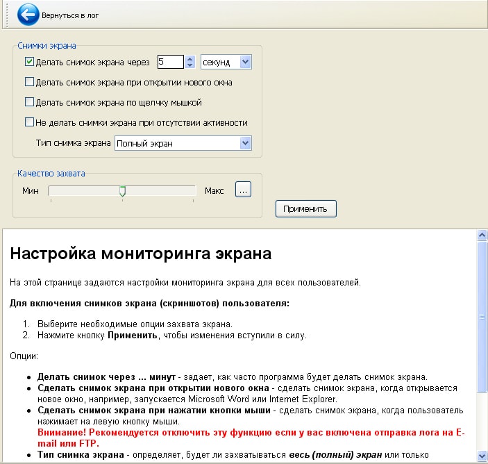
- - choice of time interval, indicated either in minutes or seconds;
- - take a photo when opening a window;
- - take a photo with a mouse click;
- - do not take a photo when you are not active;
- - snapshot mode ( Full Screen, window);
- - and the quality of the image.
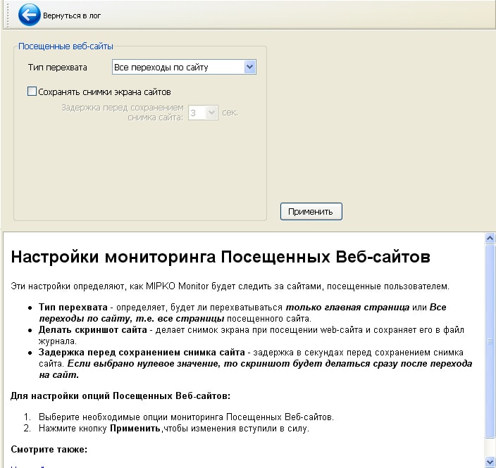
- 4. In the “visited websites” section, it’s even simpler: select the “interception type” and whether to save a screenshot.
- 5. Now about where all this will be saved or sent. In the settings section “Sending”:
- - first, set the “Log type” and the pop-up list;
- - set in what format the report “HTML” or archive “ZIP” will be saved;
- - select the sorting type and time interval for sending the report;
- - the most basic thing is where the report will be sent: to email/ftp/folder on your computer.
- - then enter your username and password and click “Apply”.
That's it, now the employees are, as they say, “Under the hood” - you can monitor the users of the local network.


