Low frequency preamplifiers. Assembling a tube preamplifier. Economical ULF with three transistors
Circuit design and application
Tube amplifier low frequencies
An audio amplifier usually consists of a preamplifier and a power amplifier (PA). The preamplifier is designed to increase the voltage and bring it to the value required for the operation of the final power amplifier; it often includes volume controls, tone controls or an equalizer; sometimes it can be structurally designed as separate device. The power amplifier must supply the specified power of electrical oscillations to the load (consumer) circuit. Its load can be sound emitters: acoustic systems (speakers), headphones (headphones); radio broadcast network or radio transmitter modulator. A low-frequency amplifier is an integral part of all sound reproducing, recording and radio broadcasting equipment.

Power amplifier as a separate unit

Technics preamplifier
Classification

Signal half-wave cutoff angles in various modes
By type of processing input signal and the circuit diagram of the amplifier output stage:
- class “A” - analog signal processing, linear mode of operation of the amplification element
- class “AB” - analog signal processing, operating mode with a large cut-off angle (>90°)
- class “B” - analog signal processing, operating mode with a cutoff angle of 90°
- class “C” - analog signal processing, operating mode with a small cutoff angle (<90°)
- class “D” - digital signal processing, pulse-width modulation is used, the amplification element operates in key mode
- class “T” - digital signal processing, pulse-width modulation is used with changing the frequency and duty cycle of the pulses

IC for use in power amplifiers
By type of application in the amplifier design of active elements:
- tube- on electronic, vacuum tubes. They formed the basis of the entire ULF fleet until the 70s. In the 60s, tube amplifiers of very high power (up to tens of kilowatts) were produced. They had significant dimensions and weight, low efficiency. and high heat dissipation. Currently, low power tube amplifiers (a few watts) are used only as part of high fidelity circuits.
- transistor- on bipolar or field-effect transistors. This design of the final amplifier stage is quite popular due to its simplicity and the ability to achieve high output power, although recently it has been actively replaced by integrated ones even in powerful amplifiers.
- integral- on integrated circuits (ICs). There are microcircuits that contain both preamplifiers and final power amplifiers on the same chip, built according to different circuits and operating in different classes. Among the advantages are the minimum number of elements and, accordingly, small dimensions.
- hybrid- some of the cascades are assembled on semiconductor elements, and some on electronic tubes. Sometimes hybrid amplifiers are also called amplifiers that are partially assembled on integrated circuits ah, and partly on transistors or vacuum tubes.
Transformer matching with load
By type of matching of the amplifier output stage with the load:
- transformer- this matching circuit is mainly used in tube amplifiers. This is due to the need to match the high output resistance of the lamp with the low load resistance. High-end transistor amplifiers also have transformer matching to the load.
- transformerless- the most common matching circuit for transistor and integrated amplifiers, because the transistor stage has a low output resistance, which is well suited to low-resistance loads.
Links
Wikimedia Foundation.
2010.
See what a “Low Frequency Amplifier” is in other dictionaries: low frequency amplifier
See what a “Low Frequency Amplifier” is in other dictionaries:- ULF Amplifier designed to amplify audio frequency signals; in a radio receiver, the ULF is turned on after the detector. [L.M. Nevdyaev. Telecommunication technologies. English-Russian explanatory dictionary reference book. Edited by Yu.M. Gornostaeva... ...
- žemadažnis stiprintuvas statusas T sritis automatika atitikmenys: engl. low frequency amplifier vok. Niederfrequenzverstärker, m rus. low frequency amplifier, m pranc. amplificateur à basse fréquence, m … Automatikos terminų žodynas audio amplifier - NDP. low frequency amplifier Electronic signal amplifier audio frequency . [GOST 24375 80] Inadmissible, not recommended low-frequency amplifier Topics radio communications General terms radio transmitters ...
- žemadažnis stiprintuvas statusas T sritis automatika atitikmenys: engl. low frequency amplifier vok. Niederfrequenzverstärker, m rus. low frequency amplifier, m pranc. amplificateur à basse fréquence, m … Automatikos terminų žodynas- 360 audio amplifier; UZCH (Low frequency amplifier) Amplifier for electrical audio signals Source: PR 45.02 97: Industry standardization system. Principles for the development of regulatory documents 360. Sound amplifier... ... Dictionary-reference book of terms of normative and technical documentation
It is proposed to rename this page to Audio Amplifier. Explanation of the reasons and discussion on the Wikipedia page: To rename / November 3, 2012. Perhaps its current name does not correspond to the norms of the modern Russian language ... Wikipedia
An electronic amplifier is an amplifier of electrical signals, the amplification elements of which use the phenomenon of electrical conductivity in gases, vacuum and semiconductors. An electronic amplifier can be an independent... ... Wikipedia
amplifier- 3.1.1 amplifier: An amplifier for audio frequency signals in a block-type detachable design or included in a single-case equipment.
Jan 15
According to the already established tradition, once a year you need to solder something worthwhile, new and useful, and since there is no cure for sound disease, for which they have not yet come up with a name and, accordingly, a cure, I wanted to do something related to sound. There is a normal amplifier, acoustics too....Oh! Pre with tone control is not enough! Well, it began. See below. To be honest, this all started about a year ago. The scheme was chosen, the parts were purchased, but suddenly, as often happens, all the zeal and desire disappeared somewhere. I put all the documentation and components into the body of the future and froze the project until better times. These times came with the onset of cold weather. And then let's go point by point.
1- Selecting a Pre-Amplifier Circuit
The most difficult theoretical part is to choose a scheme that combines high repeatability and quality of the result obtained. They dissuaded us from multiband equalizers and tone block circuits using ready-made microcircuits specially sharpened for this purpose on the forum, saying that this is a GE and is not at all suitable for obtaining high-quality sound. I also tried this preamplifier circuit with a tone control
Preamplifier circuit for TL072
In general, not bad, and for most amplifiers assembled on popular microcircuits, such as TDAхххх this will be enough. The adjustment of HF and LF is in a fairly wide range, in terms of noise it’s not the worst option, and the ease of manufacture is captivating, but you want to get results above average, so we’ll look further.
I looked at Solntsev's preamplifier. The scheme has been known for a long time, is not difficult to assemble and configure, and in terms of the ratio of good/bad reviews, the good ones outweigh by a large advantage. However, man is such a harmful creature who always wants more. I didn’t want to use Soviet components from the last century. You can assemble Solntsev using modern imported components instead of domestic ones, and people assemble them, so why not try?...
The next task was to select a tone control circuit. Active, passive, operational amplifiers, there are many options, but you need to choose one. Again, while researching the forums, I came across a discussion of Matyushkin’s tone control. A passive tone control, in which, apart from resistors and capacitors, there are no more elements, but according to reviews, such a correctly calculated TB produced some kind of special sound, very pleasant and different from other RTs.
I started “smoking” how to connect the Matyushkin tone control with the Solntsev pre-amplifier and wandered onto the сxem.net forum where I came across the topic of a high-quality Nataly pre-amplifier. This preamplifier uses just a combination of PU similar to Solntsevsky and Matyushkin’s RT. I spent several days reading the topic, which at that time was about 90 pages, but the time spent was worth it. In the end, I came to the decision to make this particular preamplifier!
2 - Adjustment of the preamplifier circuit for yourself.
The original circuit of the Natalie preamplifier and the ready-made printed circuit boards available for it did not suit me for a number of reasons. Firstly, the original has a two-level supply +/- 15V to power the op-amp and +/-30V for the rest. Well, that’s half the problem, connect the op-amp supply resistor to the +/- 30 bus and instead of 30, apply 15V in a matter of seconds. The main thing that prompted me to change the circuit and board was the size of the existing case, and according to estimates, with the boards that are available on the forum and tested, I in no way fit into the dimensions of the box. There is only one way out - to simplify the circuit a little and throw away unnecessary parts in order to reduce the size of the PCB, and this should make the board layout easier.
This is the original diagram

Nataly preamp circuit
And this is mine, a little simplified

Pre-amplifier circuit
Main differences:
1-removed several electrolytes for power supply, instead of them installed capacitors of larger capacity.
2 – cut out the tone control bypass and balance adjustment from the circuit
3 – and the third change – I also cut out the loudness compensation block at the preamplifier output.
These changes made it possible to slightly reduce the size of the printed circuit board, which was enough for the normal installation of the PCB in the PU housing.
This is how I tried on all the boards printed on paper.

Preamp Layout
It turned out that the finished device consists of 7 separate boards, or blocks. Below I will dwell on each block in more detail and try not to repeat what I wrote in a series of articles about this preamplifier in the “In Progress” section
3 – Full description of the preamplifier
3.1 – Pre-amplifier board

Signet for preamplifier
I'll start with the preamplifier board. No matter how much I would like to shove other opamps here, I will say from my sad experience - save your time and nerves, and install what you need, but you need OPA134 or their dual version OPA132. Unfortunately, at the time of ordering, these op-amps were not available in the online store, and I ordered NE5534, which, by the way, is better in overload capacity than op-amps. How much I fussed with them later, when I started setting up the pre in endless and unsuccessful attempts to get rid of the constant at the preamplifier output. I even installed 100 Ohm multi-turn trimmers, instead of resistors R9-R10, R30-R31, marked *. The output of the op-amp can be set to 0, and the output of the buffer also remains -100 - -150 mV. It seems to have no effect on hearing or sound, does not introduce any distortion, and there is no hum characteristic of constant voltage, but these millivolts should not exist!
The victims of these experiments were the headphones, one ear of which bravely died during the process of setting up the preamplifier. I eliminated the excitation in one channel, shorted the input of the opera to ground through a capacitor, soldered a capacitor of several pf, I don’t remember where, I looked at the oscilloscope and the excitation disappeared. I unsolder the capacitor, thereby opening the input and, without bothering to poke the oscilloscope into the buffer output, I connect the headphones. Something strange, there is sound in one channel, in another something farted and went silent... I looked with an oscilloscope, and there was an excitation with an amplitude of about 10 volts, which mercilessly killed the small defenseless headphone speaker. The reason for this was the same capacitor that eliminated excitation from closed entrance, but repeatedly strengthened it with open. In general, I toiled and toiled, and in the end there was nothing left but to remove these NE5534 and order OPA134.
I plugged the OPAS into the sockets, turned on the power and with trembling hands I touched the buffer output with the oscilloscope probe, and the oscilloscope beam remained in the same position! Maybe the microcircuits are defective and do not enhance anything at all? I increase the sensitivity of the oscillator, and I see that there is still a constant, but it is at the level of several mV. What is the output of the op-amp? The output is a little more, but with the help of trimmers it is reduced to zero.
Hence the conclusion. Guys, there is no need to put parts into the diagram that are not intended for this purpose. Perhaps in another scheme the same NE5534 will behave even better than the OPA, but here, among the inexpensive op-amps, it is the OPA that is needed.
3.2 – Matyushkin tone control board

Matyushkin tone control circuit
Why Matyushkin? Again, there are several reasons. Well, firstly, the original Nataly preamplifier has exactly this tone block. Secondly, the rather large dimensions of the board are compensated by the ease of assembly and the absence of any settings; it is enough to simply select the values of the parts as accurately as possible. Thirdly, my personal opinion is that any electronic enhancer, such as active tone controls, introduces its own additional bad features, and a passive tone block does not have this drawback. And the fourth reason is the shape of the frequency response of the Matyushkin tone control, which differs from other RTs. I wanted to hear it with my own ears and compare it with other tone blocks.

RT Matyushkina board
The board for RT also had to be redesigned with reduced dimensions. And besides, I didn’t find Matyushkin’s RT signet on the network with switching to the RES47 relays I have. I didn’t change anything here except the resistor that sets the depth of HF adjustment. In the original there is a 4.7 kOhm tuning resistor, but instead I soldered in a regular, constant 4.7 kOhm resistor. The control, as I said, is organized on the RES47 relay.
3.3 – control and indication board
As they say, a bad head gives no rest to your hands. The fixed buttons are small in size; attaching LEDs to them to show which relay is currently turned on would not be much work, but no! The fixed switches are somehow not interesting (it’s good that it didn’t occur to me to make touch controls), and the LEDs look rather simple. It is necessary to make a digital display and non-fixed switching, and better with one button. Write firmware? Ha! It’s no big deal when you know how to do it...damn, I don’t know how. Then there is only one way out - logic chips Made in USSR-Russia. I will not go into detail and describe the algorithm of operation of these microcircuits; I did it as best I could in the article “Nataly Preamplifier - Part 2. Control of the tone block relay and indication”, which I recommend for reading to everyone interested in this type of control.

PU control unit diagram
This is what the circuit diagram of this small board looks like, although it could consist of only eight elements S1-S4 and HL1-HL4. In general, switching of the RT relay occurs cyclically, i.e. The relays on the tone block board are switched on and off one by one and at the same time the indicator reading changes from 0 to 4. “0” corresponds to the tone control being turned off and then the bass rise increases in an incremental 1-2-3 manner. There are a lot, a lot, a lot of bottom three! If we compare it with the only factory amplifier I have, the Vega 10U-120S, the number 4 on the indicator will sound about the same as if you turn up the bass control on the Vega to the maximum and at the same time turn on the loudness compensation. So bass lovers can assemble the fourth part of Matyushkin’s RT, corresponding to the maximum low-frequency level, and enjoy life. Well, adjust the high frequencies with a variable as in conventional tone blocks.

Control and display unit board
Two more buttons switch the preamplifier inputs and the “dot/column” signal level indication mode. It can also be called an unnecessary function, but what can you do, show-off is worth more than money. And of course, I couldn’t help but make a signal level indicator, because when the LEDs blink beautifully, it looks more interesting.

Signal strength indicator on LM3915
The indicator is assembled according to a circuit tested by many on the LM3915 MS, one per channel. And since I was again limited in the size of the board, and the entire area of the main board was occupied by parts for the switches, and the central part of the LED block was forced to make a kind of two-story composite board.

Signal level indicator board on LM3915
The LM3915 microcircuits and all their hardware are on a small board, connected to the main board with a pin connector.
3.4 – power supply board
Where does the power supply start? That's right - from a transformer! But use satellite receiver as a housing for a preamplifier, dictated its own conditions for choosing a transformer for the power supply, because The height of the case is only about 4 cm and you can’t put any transformer there. Fortunately, at work I found a disassembled intercom, luckily for me, with a TP-30 transformer.

Transformer for preamplifier
An excellent transformer, easily disassembled and therefore easily rewound to the required voltage, and most importantly, in height, it seems to have been created specifically for my case. The power of the transformer is approximately 30 watts, which is enough to use this trance in a preamplifier.
I rewound it to the required voltage, assembled it using epoxy resin as usual, apparently I guessed well with the ratio of resin and hardener, and after assembly the transformer does not make a sound.

Preamp power supply
For the pre it was necessary to get three different voltages: +/- 15V to power the preamp board, 9V to power the relay and indication board, and 5V for the sound card. For each voltage, I wound a separate winding and installed three diode bridges.

Power supply circuit for preamplifier
I love stabilized voltage, so I made a stabilized power supply on LM317 / LM337 to power the preamplifier. To fine-tune the output voltage, multi-turn trimmers were installed in each arm for the LMok. At the output, for additional smoothing, I soldered 1 Ohm resistors. A relay located on the indication board rested on one of the LMoks, so she moved to live on the back side of the board.

LM317 power supply for preamplifier
I also made a 5V stabilizer using LM317 standard scheme, but without a trimmer, but with an ordinary constant resistor, because There are additional stabilizers on the DAC board.
9 Volt made it even simpler by using the 7809 chip as a stabilizer. Here, the presence of noise will not affect the sound in any way and the circuit can be simplified, but stabilization is required for stable operation of logic chips
Next in line >>>
3.5 – feeUSBsound card onPCM 2704

Sound card based on PCM2704
A series of articles about “DAC building” on the datagor pushed me to try to build a USB for myself sound card. This card represents digital-to-analog converter, i.e. when you connect this board to a computer, it is determined as sound device. Incoming digital signal payment goes through USB cable, and at the output we get the usual one, familiar to our ears sound signal. I chose to repeat the most simple diagram on the PCM2704 chip in order to listen to whether such a sound card actually plays better than the sound card installed in the computer.

Scheme USB audio cards on PCM2704
Before that, I listened to all amplifiers and headphones via the Creative Audigy2 PCI card and was very pleased with it. I’ll skip the assembly part, after all, this is not specifically about assembling the DAC, but about brief overview sound card as part of a preamplifier. I can say that the result exceeded my expectations. In fact, the sound made by this little card turned out to be better sound with Audigy 2 and especially built-in motherboard chip. During the assembly of the preamplifier, I was forced to switch again to “in-computer” sound due to the impossibility turning on USB, and what a weak and blurry sound it is that comes from the built-in chip. There is no transparency or airiness, as if the drawing was drawn with a pencil, and then all the lines were lightly erased with a finger. It seems that there is bass and highs, but everything is somehow different and not natural.
Now, as for directly USB installation sound card into the preamplifier housing. At the beginning I didn’t even plan to place it in the preamp housing, but after thinking and estimating that one and a half meters of cheap signal cable from the preamplifier to the amplifier would be better than one and a half meters of “preamplifier-amplifier” cable + the same amount from the “audio-preamplifier”, as this would be the case if the sound card was used in the form in which it was, that is, in a separate case. Therefore, I placed the sound card board in the preamplifier housing, thereby reducing the length of the “sound card-preamplifier” cable from one and a half meters to 10 centimeters. Meals were planned to be made, not from USB input, but from the preamplifier power supply, because in theory, the quality of power from a separate transformer source should be better than that, which comes from the computer USB input. In fact, I didn’t notice the difference either with my ears or with an oscilloscope. And the five-volt power supply bus of the power supply was left hanging in the air without use. The sound box is powered the same way - from USB, and there’s one thing about it: big advantage– you don’t need to turn on the preamp every time you want to listen to music through headphones.
So, I advise everyone to assemble at least such a simple sound card, you will be very pleased with the result. Or buy a ready-made one if you lack the skills to assemble digital devices.
3.6 – volume and treble control board

Volume and HF control board
The smallest board of the entire device, not of particular interest. There are only two parts installed on it - a variable volume control resistor and a treble control variable. Two wire loops go from this board, one, a volume control cable, to the input selector board. The second RF control loop goes to the tone control board. There is nothing more to write about this board.
3.7 – input selector board

Input selector board
And the last part of the preamplifier is the input selector board, although it might be a stretch to call it that, it still has only 2 inputs. The board has three connectors: 2 double tulips and a mini jack. Switching occurs through relay RES 47, also installed on this board. In the absence of power to the relay, the contacts coming from the sound card are closed with the input contacts of the preamplifier board; when power is supplied to the relay, this circuit breaks and the contacts of the preamplifier input are closed with the “tulip” audio input. That is, the board has the ability to switch only two inputs, or the sound is coming with a sound card built into the PU case, or with external source via tulip connectors. Another double “tulip” is designed to output a signal from the preamplifier, and the mini jack is rigidly connected to the output of the sound card. You can connect another amplifier to it, which will receive a “clean” signal not decorated with a pre-amplifier, or, as in my case, I use this output from the sound card to connect headphones.
4 – pre-amplifier settings
By by and large There is only one part of the preamp that needs tuning, and that part is the preamp board itself. For normal operation circuit, you need to set the quiescent current of the output transistors and this is done by selecting the resistance of resistors R9-R10, R30-R31 in (the original circuit is 51 Ohm). For this circuit, the recommended quiescent current is 20-22mA, which corresponds to a voltage drop of 300-350mV across resistors R20,R21,R40,R42 with a nominal value of 15 Ohms. Calculating the quiescent current is very simple; to do this, you need to divide the voltage drop across these resistors by their resistance. 300:15=20, i.e. when the voltage drop across resistors R20, R21, R40, R42 is 300 mV, our quiescent current will be 20 mA. One important point, in which some novice solders make a mistake. The voltage drop across resistors is measured by connecting the voltmeter probes of one terminal of the resistor to another terminal of the same resistor, and not to the common wire. An obvious thing, but out of habit you can connect one terminal to a resistor and the second to the common one, and get a very surprising result. If your voltage drop is outside the range of 300-350 mV, then depending on the deviation up or down, you need to change the value of resistors R9-R10, R30-R31. To increase the current, you need to increase the resistance of the resistors, and to decrease it, respectively, solder resistors with lower resistance. In general, to reduce problems with the selection of these resistors, you can do the following - solder tuning multi-turn 100 Ohm resistors in place of the constant resistors and easily adjust and change the quiescent current at your discretion.

Setting the Preamplifier Quiescent Current
The board does not provide for the installation of such resistors, but since... For adjustment, only 2 pins of the trimmer are used out of 3; we simply solder the middle leg of such a resistor to one of the outer ones, and solder it in place of the permanent one. In the future, for the final setting of the quiescent current, you can measure the resistance at the trimmer and already with high accuracy select a constant resistor of the required resistance.
Now you need to look at the presence of a constant at the output of each buffer and all 4 operational amplifiers. At correct assembly and using exactly those components that are needed, it should be several mV, no more than 5-10 mV. If you see several tens of mV there, it means either you have something soldered incorrectly somewhere, or you soldered in a resistor of the wrong value by mistake, or there is an exciter somewhere, and you will need an oscilloscope to find it. If you have trimming resistors installed, you can try to set it to “0” by selecting the resistance of these two resistors, for example R9 and R10 for the first buffer. There will be a slight imbalance in the resistance of the resistors in the positive and negative arms, but there will be a stable zero at the output of the op-amp and buffer. It should be remembered that changing the resistance of these resistors leads to a change in the quiescent current, so I advise you to connect two voltmeters, or a voltmeter + oscilloscope and observe their readings. So that the voltage drop does not go beyond the recommended limits, and the constant is close to zero. I forgot to say that all these adjustments must be made with the preamplifier input closed.
To search for an excitation, you need to look at the signal shape at various points. Depending on the point on the diagram to which you will connect the oscilloscope, there should be a straight line, without various “hedgehogs” characteristic of excitation. In my case, such a “hedgehog”, i.e. a 0.5V signal shaped like a sine wave of several megahertz was at the emitter of the VT3 transistor; this problem was easily solved by soldering a 20pF capacitor between the base and collector of this transistor. I did not detect any excitation in the other three buffers.

Checking the square wave on the preamplifier
At the output we should see clear rectangles, but if there is some kind of nasty stuff there, we look for an error.
Regarding the errors. Parts should be selected very carefully, and each part should be additionally checked before installation. Again a case from personal experience. Everything works, the meander is good, I connect it to the generator and see that after 7 kHz there is a clear blockage. After a careful inspection, which took a lot of time, I discovered that instead of a 10pF capacitor, which stands between the 2 and 6 legs of the op-amp and serves to eliminate possible excitation at high frequencies (several MHz), I have a 100pF capacitor, which cuts off everything above 7 kHz. I replaced it with the required one, 10pF, and the frequency response became uniform.
As for the relay control and indication board. Not everything is so smooth and clear here. Firstly, I was unpleasantly surprised by the quality of domestic parts, half of which turned out to be defective. Secondly, those who seem to be workers behave completely incomprehensibly. Either they work every other time, or they work in an algorithm known only to them. Let me explain what exactly I mean.
Let's take the K176IE4 microcircuit. When the power is turned on, for a reason known only to her, either 0 or 1 lights up on the screen. When it turns on with one, everything is fine, the tone block modes correspond to the number on the indicator, i.e. 0 – minimum LF, 3 – maximum. When it turns on with zero, then the minimum is already at 3, and the maximum at 2. It turns out that the K561IE9A counter counts everything correctly, but the IE4 is glitching. In addition to this, sometimes false positives occur, i.e. I press the button once, and the number from 1 jumps to 3 or even 0.
The same thing with K155TM2, which controls the input selector and switching signal level modes. I assembled two switches using absolutely the same circuit, in the end one switch works like a clock, the other needs to be pressed 5 times for it to work. How can this be?...They solder in another microphone, it doesn’t want to switch anything at all. IN general method I soldered it at scientific level, I don’t remember which legs of the capacitors of several pF, and now the switching seems to be stable. I will not indicate these capacitors on the diagram so as not to mislead, assemble according to the standard connection diagram, and then be guided by the circumstances.
5. – Ground layout
I was afraid of this moment based on personal experience, because problems usually arise at this stage with the correct ground wiring and connecting the common wire. A clear sign incorrect wiring is a characteristic hum, indicating that an earth loop or other irregularities have formed somewhere. In the case of the preamplifier, I took a different route, to do it not in a more beautiful way and with fewer wires, but in a more correct way. And ultimately I got a positive result. There is no background, even with the volume knob turned up to maximum, there is no hum from the wrong ground either, overall result exceeded my expectations.

Preamplifier ground routing
How did I connect the common wires...Very simple. I brought everything to one point, and this point turned out to be a board for volume and treble controls. For example, in the power supply of the pre-amplifier board, the positive and negative wires were soldered to the PU board itself, and the common wire to the regulator board, and then a short wire was soldered from the RG and HF board to the common track of the PU board. I did the same with other general wiring, numerous tentacles of the electric octopus they go from the adjustment board to all the others.

Pre-amplifier block diagram
I tried to draw a flowchart of all this. I hope that I didn’t confuse anything and that it turned out more or less clear.
6. Body.
The case, as I already said, fits perfectly with the Odissey satellite receiver. It won me over with its large window, which displayed the clock, channel number and other information, as well as the size of the case. Cases similar in size from DVD players significantly lower, and also have a compartment for loading a disk, which entails redoing the front panel; in this case, nothing needed to be remade. For final finishing, all I had to do was drill two holes in the “face” for attaching the volume and treble controls, and paint over the unnecessary inscriptions. I used paint as usual - aerosol from a car dealership. The matte black color matched the color of the panel exactly, so there was no need to even paint the entire panel; the work was reduced to carefully painting over the inscriptions and installing aluminum handles.

Preamplifier front panel

Volume and tone control knobs
I used some tricks when installing the input selector board. Standard way It was not possible to install it, because... The tone control board was in the way, and I had no choice but to screw it upside down and additionally tighten it with a plastic clamp.

Input selector board
All boards are secured through plastic bushings. A screw is screwed into the bushing (or spacer), a hole is drilled in the board along the outer diameter of the bushing, the whole thing is tightened from above with a nut, and the board is reliably isolated from contact with the case.

Insulator for board from case
You can also see that small L-shaped radiators cut from an aluminum plate were screwed to the transistors on the preamplifier board. The radiators are not large at all, but the temperature of the transistors has decreased significantly.
For reliability, all the wires soldered to the boards were filled with hot glue.
I put a cardboard spacer under the power supply board, just in case.

Insulating gasket for power supply board
Although there is a margin of several mm between the board and the case, I made additional control insulation to be on the safe side. After all, there is a power switch on the board and you accidentally get on metal case There is no particular desire for contact with 220V.
The result was as in the saying “In cramped conditions, but don’t be offended.” Everything is crowded, everything is dense, but nothing gets in the way.

Pre-amplifier layout
The 3G card board feels like a king, there are still a couple of free centimeters around it! In order to reduce possible interference from the transformer, I covered it with a metal cover. And during the tests it turned out that the 9-volt stabilizer gets very hot. I had to attach a small radiator to it.
7. – conclusion.

Preamplifier housing
This is not a small article, but the work done was also not small, and what I would like to say in conclusion. Do you want to be honest? Made another toy! Yes, it glows and winks, yes, the sound has become brighter and it’s possible to adjust high and low frequencies, yes, in fact, Matyushkin’s tone control somehow decorates the sound in its own special way, but overall there’s some kind of dramatic improvement , which makes you want to jump to the ceiling, unfortunately not... The sound has become more interesting, but nothing more. Do not think that I speak badly about the scheme or dissuade you from repeating it, under no circumstances! If you are a real radio amateur “sick with sound”, then you will get a lot of pleasure from the very process of assembling the device, and I myself don’t even regret the time and effort spent, because in the end I got quite a lot in my arsenal quality item, which allows you to enrich the sound and customize it to your preferences. I won’t hide the fact that after assembling the preamp, I listen to music not directly through the sound card, but through this preamplifier. All I'm saying is that my auditory receptors couldn't make me squeal with joy. Perhaps the acoustics are not right, perhaps the amplifier, perhaps the ears. Speaking of the amplifier, I have only connected this pre so far to a hybrid on the field, I will need to connect it to my favorite pure tube amplifier on G807 and listen to what he has to say about this combination.

Collected pre!
In general, friends! Here are the finished seals, personally tested by me. I would like to warn you about the control board, it may differ slightly from the diagram, because... has been improved many times.
Solder, try, experiment, maybe this is exactly what you were looking for! Don’t listen to anyone, including me, because each of you has your own tastes and preferences, as they say, taste and color... I hope the article was useful and will give some of you the starting kick for assembling this pre-amplifier.
As is known, the rated output voltage of modern audio frequency signal sources (3Ch) does not exceed 0.5 V, while the rated input voltage of most 3Ch power amplifiers (UMZCH) is usually 0.7..1 V. To increase the signal voltage to level that ensures normal operation of the UMZCH, as well as to match the output impedances of the signal sources with its input impedance, 3CH pre-amplifiers are used. As a rule, it is in this part of the sound reproduction path that volume, timbre and stereo balance are adjusted. The main requirements for preamplifiers are low nonlinear signal distortion (harmonic distortion - no more than a few hundredths of a percent) and a low relative level of noise and interference (not higher than -66..-70 dB), as well as sufficient overload capacity. All these requirements are largely met preamplifier Muscovite V. Orlov (he took the AU-X1 amplifier circuit of the Japanese company "Sansui" as a basis). Nominal input "and output voltage amplifier 0.25 and 1 V, respectively, the harmonic coefficient in the frequency range 20..20000 Hz at the rated output voltage does not exceed 0.05%, and the signal-to-noise ratio is 66 dB. The input impedance of the amplifier is 150 kOhm, the tone control limits (at frequencies of 100 and 10000 Hz) are from -10 to +6 dB. The device is designed to work with UMZCH, the input impedance of which is at least 5 kOhm.
The amplifier (Fig. 1 shows a schematic diagram of one of its channels) consists of a source follower on transistor VT1, a so-called bridge passive tone control (elements R6-R11.1, C2-C8) and a three-stage symmetrical signal voltage amplifier. The volume control - variable resistor R1.1 - is included at the amplifier input, which reduces the likelihood of its overload. The timbre in the region of lower frequencies of the audio range is regulated by a variable resistor R7.1, in the region higher frequencies- variable resistor R11.1 (resistors R7.2 and R11.2 are used in another channel of the amplifier). The transfer coefficient of a symmetrical amplifier is determined by the ratio of the resistances of resistors R18, R17 and, with the values indicated in the diagram, is approximately 16. The operating mode of the final stage transistors (VT6, VT7) is determined by the voltage drop created by the collector currents of transistors VT4, VT5 on diodes VD1 connected in the forward direction - VD3. Trimmer resistor R15 serves to balance the amplifier. The amplifier can be powered either from the source that powers the UMZCH, or from any unstabilized rectifier with output voltages of +18..22 and -18..22 V.
A possible version of the printed circuit board for one channel of the device is shown in Fig. 2.
 |
It is made of foil fiberglass laminate with a thickness of 1.5 mm and is designed for the installation of resistors MLT and SP4-1 (R15), capacitors MBM (C1, C4, C8, C11), BM-2 (C3, C5-C7) and K50-6 , K50-16 (rest). Capacitors MBM and BM-2 are mounted vertically on the board (one of their terminals is extended to the locally required length using tinned wire with a diameter of 0.5..0.6 mm). Double variable resistor R1 of any type of group B, resistors R7 and R11 - group B. Transistors KP303D can be replaced with KP303G, KP303E, transistor KP103M - with KP103L, transistors KT315V and KT361V - with transistors of these series with index G. Field-effect transistors must be selected according to the initial drain current, which at voltage Uс=8 V should not go beyond 5.5..6.5 mA. D104 diodes are completely replaceable with diodes of the D220, D223, etc. series. The adjustment comes down to setting the trimmer resistor R15 to zero voltage at the output and selecting the resistor R18 until an output voltage equal to 1 V is obtained at an input voltage of 250 mV with a frequency of 1000 Hz (the sliders of resistors R7, R11 are in the middle position, and resistor R1 is in the upper position in the circuit ).
A significant drawback of the described, and many others similar devices on transistors - comparatively big number elements and, as a consequence, quite large dimensions circuit board. Pre-amplifiers based on operational amplifiers (op-amps) are much more compact.
An example is a device developed by Muscovite Yu. Solntsev based on the general-purpose OS K574UD1A (Fig. 3).
 |
His studies showed that the harmonic coefficient of this op-amp strongly depends on the load: it is quite acceptable when its resistance is more than 100 kOhm, it increases to 0.1% when the load resistance decreases to 10 kOhm. To obtain small enough nonlinear distortion the author added to the specified op-amp a so-called parallel amplifier, characterized by the virtual absence of “step” distortion, even without a negative feedback(OOS). With OOS, the harmonic coefficient does not exceed 0.03% in the entire audio frequency range with a load resistance of more than 500 Ohms. The remaining parameters of the pre-amplifier are as follows: nominal input and output voltages 250 mV, signal-to-noise ratio at least 80 dB, overload capacity 15..20 dB. As can be seen from the diagram, the device consists of linear amplifier with horizontal frequency response on op-amp DA1 and transistors VT1-VT4 ("parallel" amplifier) and a passive bridge tone control (elements R12-R14, R17-R19, C6-C9). If necessary, this regulator can be excluded from the path using relay K1 (the signal in this case is removed from the voltage divider R10R11). The amplifier's transmission coefficient is determined by the ratio of the resistance of resistor R3 to the total resistance of resistors R2, R4. The bridge regulator has no special features. At lower frequencies, the timbre is adjusted with a variable resistor R18.1, at higher frequencies with a resistor R13.1. Resistors R12, R14 prevent monotonous rise and fall of the frequency response outside the nominal frequency range of the amplifier. For normal operation of the tone control, the load resistance must be at least 50 kOhm. When working with a signal source whose output voltage contains a constant component, it is necessary to turn on a separating capacitor at the amplifier input (shown in the diagram with dashed lines).
 |
All parts of the amplifier, with the exception of the tone control elements, are mounted on printed circuit board made of foil fiberglass (Fig. 4 shows part of it for one channel). The board is designed for mounting resistors MLT, SP4-1 (R4), capacitors K53-1a, K53-18 (C1, C4), KM-6B (C2, C3, C5, C6) and MBM (others). Double variable resistors R13 and R18 - any type of group B. The tone control elements are mounted directly on their terminals and connected to the board with shielded wires. Instead of those indicated in the diagram, transistors KT3107I, KT313B, KT361K (VT1, VT4) and KT312V, KT315V (VT2, VT3) can be used in the amplifier. Relay K1 - brand RES60 (passport RS4.569.436) or any other with suitable dimensions and operating current and voltage. Diode VD1 - any with acceptable reverse voltage not less than 50 V. For connection to the amplification path, a detachable connector MRN14-1 is used (its plug is installed on the board). To power the amplifier, a bipolar power supply is required, capable of delivering a current of about 30 mA to the load at a ripple voltage of no more than 10 mV (otherwise, if the installation is unsuccessful, a noticeable background may appear). Adjusting the amplifier comes down to setting the required transmission ratio with and without a connected tone control. In the first case, the desired result is achieved by changing the resistance trim resistor R4 (and if necessary, then by selecting resistor R2), in the second - by selecting resistor R11. The amplifier is designed to work with UMZCH, described in the article by Yu. Solntsev “High-quality power amplifier” (Radio, 1984, No. 5, pp. 29-34). The volume control (double variable resistor of group B with a resistance of 100 kOhm) is switched on in this case between its input and the output of the pre-amplifier. The same resistor, but group A, is used as a stereo balance regulator (one of its outer terminals and the engine output in each channel is connected to the volume control slider, and the other outer terminal is connected to the UMZCH input).
In recent years, the industry has mastered the production of integrated circuits (ICs KM551UD, KM551UD2), specially designed for operation in the input stages of audio frequency paths of household radio equipment (preamplifiers-correctors of electric players, amplifiers for recording and playback of tape recorders, microphone amplifiers, etc. devices). They are distinguished by a reduced level of self-noise, low harmonic distortion, and good overload capacity.
 |
Figure 5 shows the circuit of a pre-amplifier based on the KM551UD2 IC (proposed by Muscovite A. Shadrov). This IC is a dual op-amp with a supply voltage from +5 to +16.5 V. An IC with index A differs from a device with index B in half the input common-mode voltage (4 V) and the normalized noise voltage referred to the input (no more than 1 µV when the signal source resistance is 600 Ohms; for KM551UD2B it is not standardized). The nominal input and output voltages of this amplifier are the same as those of the device according to the circuit in Fig. 1, harmonic distortion in the frequency range 20..20000 Hz no more than 0.02%, signal-to-noise ratio (unweighted) 90 dB, Adjustment range volume and timbre (at frequencies 60 and 16000 Hz) respectively 60 and +10 dB, transition attenuation between channels in the frequency range 100..10000 Hz is not less than 50 dB. The input and output impedances of the amplifier are 220 and 3 kOhm, respectively. Bridged tone control included in this case into the OOS circuit, covering the op-amp DA1.1 (hereinafter, the pin numbers of the second op-amp of the microcircuit are indicated in parentheses). At the input there is a fine-compensated volume control on a variable resistor R2.1 with a tap from a conductive element. Loudness compensation (raising low-frequency components at low volume levels) can be turned off using switch SA1.1. Stable operation of the KM551UD2 IC (its frequency response has three bends) is ensured by capacitor C7 and circuit R5C5, the values of which are selected for the transfer coefficient Ki = 10 (the rate of rise of the output voltage with such amplification reaches 3..4 V/μs). Capacitors C12, C13 prevent the amplifier from interconnecting with other devices in the path when powered from a common source. The variable resistor R12.1 (in another channel R12.2) regulates the stereo balance.
 |
All parts of the amplifier, except for variable resistors R2, R7, R11 and switch SA1, are mounted on a printed circuit board made of foil fiberglass. It is designed for the installation of MLT resistors, capacitors MBM (C1, C10), BM-2 (C3-C5, C11), KM (C6, C7, C12, C13) and K50-6, K50-16 (others). Capacitors MBM and BM-2 are mounted vertically. Any dual variable resistors of group A are suitable for regulating volume and stereo balance; resistors of group B are suitable for regulating tone. The amplifier does not require adjustment. The frequency response of bridge tone controls, as is known, has fixed inflection frequencies, therefore, in essence, only the slope of the frequency response sections to the left and right of these frequencies is smoothly adjusted, and its maximum value does not exceed 5..6 dB per octave. To obtain the required limits of tone control at higher and lower frequencies of the audio range, the inflection frequencies must be selected in the mid-frequency region. Such a regulator is ineffective if it is necessary to suppress low- or high-frequency interference in the signal spectrum. For example, with a corner frequency of 2 kHz, the tone control can reduce the level of interference at a frequency of 16 kHz by 15 dB, only at the same time attenuating the spectrum components of 8 and 4 kHz by 10 and 5 dB, respectively. It is clear that in such a case This is not a way out, therefore, to suppress interference at the edges of the spectrum, switchable low-pass (LPF) and high-pass (HPF) filters with a large slope of the frequency response slope outside the transparency band are sometimes used. However, in this case too desired result This is not always achieved, since these filters usually have fixed cutoff frequencies. It's a different matter if the filters are made tunable in frequency. Then, by smoothly shifting the boundaries of the transmitted frequency range in the desired direction, it will be possible to “remove” the interference beyond its limits without affecting the shape of the frequency response within the range. By the way, it is advisable to make such filters non-switchable: they will help combat infra-low-frequency interference from the mechanism of an insufficiently advanced electric player.
Low frequency amplifiers (LF) are used to convert weak signals predominantly in the audio range over powerful signals, acceptable for direct perception through electrodynamic or other sound emitters.
Note that high-frequency amplifiers up to frequencies of 10... 100 MHz are built according to similar circuits; the difference most often comes down to the fact that the capacitance values of the capacitors of such amplifiers decrease as many times as the frequency of the high-frequency signal exceeds the frequency of the low-frequency one.
A simple amplifier with one transistor
The simplest ULF, made according to the scheme with common emitter, shown in Fig. 1. A telephone capsule is used as a load. The permissible supply voltage for this amplifier is 3...12 V.
It is advisable to determine the value of the bias resistor R1 (tens of kOhms) experimentally, since its optimal value depends on the supply voltage of the amplifier, the resistance of the telephone capsule, and the transmission coefficient of a particular transistor.
Rice. 1. Circuit of a simple ULF on one transistor + capacitor and resistor.
For selection initial value resistor R1, it should be taken into account that its value should be approximately one hundred or more times greater than the resistance included in the load circuit. To select a bias resistor, it is recommended to connect a constant resistor with a resistance of 20...30 kOhm in series and variable resistance 100... 1000 kOhm, after which, applying a small amplitude audio signal to the amplifier input, for example, from a tape recorder or player, by rotating the knob variable resistor achieve the best signal quality at the highest volume.
The capacitance value of the transition capacitor C1 (Fig. 1) can range from 1 to 100 μF: the larger the value of this capacitance, the lower frequencies the ULF can amplify. To master the technique of amplifying low frequencies, it is recommended to experiment with the selection of element values and operating modes of amplifiers (Fig. 1 - 4).
Improved single-transistor amplifier options
More complicated and improved compared to the diagram in Fig. 1 amplifier circuits are shown in Fig. 2 and 3. In the diagram in Fig. 2, the amplification stage additionally contains a chain of frequency-dependent negative feedback (resistor R2 and capacitor C2), which improves the quality of the signal.

Rice. 2. Diagram of a single-transistor ULF with a chain of frequency-dependent negative feedback.

Rice. 3. Single-transistor amplifier with a divider to supply bias voltage to the base of the transistor.

Rice. 4. Single-transistor amplifier with automatic bias setting for the transistor base.
In the diagram in Fig. 3, the bias to the base of the transistor is set more “rigidly” using a divider, which improves the quality of operation of the amplifier when its operating conditions change. “Automatic” bias setting based on an amplifying transistor is used in the circuit in Fig. 4.
Two-stage transistor amplifier
By connecting two simple amplification stages in series (Fig. 1), you can obtain a two-stage ULF (Fig. 5). The gain of such an amplifier is equal to the product of the gain factors of individual stages. However, it is not easy to obtain a large stable gain with a subsequent increase in the number of stages: the amplifier will most likely self-excite.

Rice. 5. Circuit of a simple two-stage low-frequency amplifier.
New developments of low-frequency amplifiers, the diagrams of which are often given on the pages of magazines recent years, pursue the goal of achieving a minimum nonlinear distortion factor, increasing output power, expanding the amplified frequency band, etc.
At the same time, during setup various devices and conducting experiments, you often need a simple ULF, which can be assembled in a few minutes. Such an amplifier must contain a minimum number of scarce elements and operate over a wide range of changes in supply voltage and load resistance.
ULF circuit based on field-effect and silicon transistors
The circuit of a simple low-frequency power amplifier with direct coupling between stages is shown in Fig. 6 [Rl 3/00-14]. The input impedance of the amplifier is determined by the rating of potentiometer R1 and can vary from hundreds of ohms to tens of megohms. You can connect a load with a resistance from 2...4 to 64 Ohms and higher to the amplifier output.
For high-resistance loads, the KT315 transistor can be used as VT2. The amplifier is operational in the range of supply voltages from 3 to 15 V, although its acceptable performance is maintained even when the supply voltage is reduced to 0.6 V.
The capacitance of capacitor C1 can be selected in the range from 1 to 100 μF. In the latter case (C1 = 100 μF), the ULF can operate in the frequency band from 50 Hz to 200 kHz and higher.
Rice. 6. Scheme simple amplifier low frequency on two transistors.
The amplitude of the ULF input signal should not exceed 0.5...0.7 V. The output power of the amplifier can vary from tens of mW to units of W depending on the load resistance and the magnitude of the supply voltage.
Setting up the amplifier consists of selecting resistors R2 and R3. With their help, the voltage at the drain of transistor VT1 is set equal to 50...60% of the power source voltage. Transistor VT2 must be installed on a heat sink plate (radiator).
Track-cascade ULF with direct coupling
In Fig. Figure 7 shows a diagram of another seemingly simple ULF with direct connections between cascades. This kind of communication improves frequency characteristics amplifier in the low-frequency region, the circuit as a whole is simplified.

Rice. 7. Schematic diagram three-stage ULF with direct connection between stages.
At the same time, tuning the amplifier is complicated by the fact that each amplifier resistance has to be selected individually. Approximately the ratio of resistors R2 and R3, R3 and R4, R4 and R BF should be in the range (30...50) to 1. Resistor R1 should be 0.1...2 kOhm. Calculation of the amplifier shown in Fig. 7 can be found in the literature, for example, [R 9/70-60].
Cascade ULF circuits using bipolar transistors
In Fig. 8 and 9 show circuits of cascode ULFs using bipolar transistors. Such amplifiers have a fairly high gain Ku. Amplifier in Fig. 8 has Ku=5 in the frequency band from 30 Hz to 120 kHz [MK 2/86-15]. ULF according to the diagram in Fig. 9 with a harmonic coefficient of less than 1% has a gain of 100 [RL 3/99-10].

Rice. 8. Cascade ULF on two transistors with gain = 5.

Rice. 9. Cascade ULF on two transistors with gain = 100.
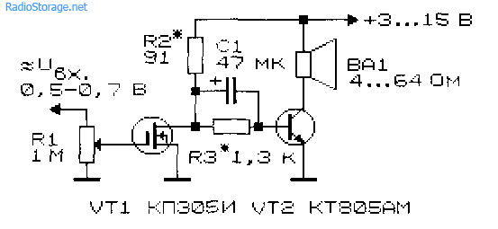
Economical ULF with three transistors
For portable radio-electronic equipment important parameter is the efficiency of ULF. The diagram of such a ULF is shown in Fig. 10 [RL 3/00-14]. Here, a cascade connection of field-effect transistor VT1 and bipolar transistor VT3, and transistor VT2 is turned on in such a way that it stabilizes the operating point of VT1 and VT3.
As the input voltage increases, this transistor shunts the emitter-base junction of VT3 and reduces the value of the current flowing through transistors VT1 and VT3.

Rice. 10. Simple scheme economical amplifier LF on three transistors.
As in the above circuit (see Fig. 6), the input resistance of this ULF can be set in the range from tens of ohms to tens of megohms. A telephone capsule, for example, TK-67 or TM-2V, was used as a load. The telephone capsule, connected using a plug, can simultaneously serve as a power switch for the circuit.
Voltage ULF power supply ranges from 1.5 to 15 V, although the functionality of the device is maintained even when the supply voltage is reduced to 0.6 V. In the supply voltage range of 2... 15 V, the current consumed by the amplifier is described by the expression:
1(μA) = 52 + 13*(Upit)*(Upit),
where Upit is the supply voltage in Volts (V).
If you turn off transistor VT2, the current consumed by the device increases by an order of magnitude.
Two-stage ULF with direct coupling between stages
Examples of ULFs with direct connections and minimal selection of operating modes are the circuits shown in Fig. 11 - 14. They have high gain and good stability.

Rice. 11. Simple two-stage ULF for a microphone (low noise level, high gain).

Rice. 12. Two-stage low-frequency amplifier using KT315 transistors.

Rice. 13. Two-stage low-frequency amplifier using KT315 transistors - option 2.
The microphone amplifier (Fig. 11) is characterized low level self-noise and high gain [MK 5/83-XIV]. An electrodynamic type microphone was used as the VM1 microphone.
A telephone capsule can also act as a microphone. Stabilization of the operating point (initial bias at the base of the input transistor) of the amplifiers in Fig. 11 - 13 is carried out due to the voltage drop across the emitter resistance of the second amplification stage.

Rice. 14. Two-stage ULF with field-effect transistor.
The amplifier (Fig. 14), which has a high input resistance (about 1 MOhm), is made on a field-effect transistor VT1 (source follower) and a bipolar transistor - VT2 (with a common one).
Cascade low frequency amplifier field effect transistors, which also has a high input impedance, is shown in Fig. 15.

Rice. 15. circuit of a simple two-stage ULF using two field-effect transistors.
ULF circuits for working with low-Ohm loads
Typical ULFs designed to operate with low-impedance loads and having output power tens of mW and above are shown in Fig. 16, 17.

Rice. 16. A simple ULF for working with a low-resistance load.
Electrodynamic head BA1 can be connected to the output of the amplifier, as shown in Fig. 16, or diagonally to the bridge (Fig. 17). If the power source is made of two series-connected batteries (accumulators), the right output of the head BA1 according to the diagram can be connected to their midpoint directly, without capacitors SZ, C4.

Rice. 17. Circuit of a low-frequency amplifier with the inclusion of a low-resistance load in the diagonal of the bridge.
If you need a circuit for a simple tube ULF, then such an amplifier can be assembled even using one tube, look at our electronics website in the corresponding section.
Literature: Shustov M.A. Practical circuit design (Book 1), 2003.
Corrections in the publication: in Fig. 16 and 17, instead of diode D9, a chain of diodes is installed.
©The word "preamp" is used in different ways by different manufacturers, marketers, and users. This is one of the most widely interpreted terms when discussing audio equipment; if you ask for "pre-amp", you may also ask for "furniture". No one will know exactly what you want. Let's figure out what a preamplifier is?
Why do I need a preamp and do I need one?
A preamplifier is a “head amplifier,” and as the name suggests, it prepares the signal coming from the source or microphones for further amplification. There are a number of reasons to buy:
Whether or not a preamp is needed.
When you plug your DAC or microphone directly into an amplifier, what does it sound like?
- Is this signal enough?
- Is it balanced?
- Clean?
If this is not the case, then you probably need to buy a preamp.
By the way, a good separate preamplifier produces less interference, interference and other noise than, for example, a full one  amplifier. Whenever a signal is amplified, the goal is to maintain the signal-to-noise ratio as
  possible in best quality. This makes a lot of sense because interference and interference from the preamp can cause a non-linear sound when the signal is amplified. To avoid introducing additional noise from the preamp, it should be placed in a separate unit and as close to the signal source as possible, like this.
A preamp is part of an amplifier. This means that the preamplifier will allow you to connect a variety of sources, such as a CD tuner or a DAC. 
The preamp allows you to change the volume and possibly change the HF and LF parameters.
By the way, 90% of preamps have a phono stage, which is what you need to connect your turntable.
Finally, one of the reasons to buy a preamp is to switch multiple signals.
All combined systems require pre-amplification.
There's also a multi-channel preamp that combines the signals for you and creates a single output signal for the amplifier. The multi-channel preamp also allows you to adjust the equalizer and power of each signal depending on your needs.

An amplifier can be divided into two main parts - a preamplifier and a power amplifier.
Amplifier 
One way to get more High Quality sound was to separate the two sections of the amplifier. By separating the preamp and power amplifier, you could design a dedicated power supply to drive electronics with finer signals without outside intervention noisy circuits power amplifier. In some cases, even the power supply is split in another case to reduce noise in the preamp.
Preamplifiers can also be "passive". They do not require power since the components (mostly  switch and volume control) are operated directly from your sources (). Theoretically this is The best way, but in practice they have quite a lot of disadvantages, but a passive preamplifier is a relatively rare type.
When we talk about a preamplifier, we usually mean a preamplifier in a separate unit. Such a preamplifier is housed in a separate housing, and it has many controls for controlling the power amplifier to control the acoustics and switch.

The preamp can also be built in as an instrument, pedal, rack unit, mixer, sound card, or a variety of other forms; and the preamplifier can also act as the input stage of each head amplifier. 
Not every preamp can effectively drive a power amplifier. Others may be designed to increase the signal level to drive the input.
Some preamps have gain control, while others have a fixed gain amount. In any case, they typically have a volume knob that simply passively turns the overall signal level at the very end of the preamp chain. Also, the preamp may have a tone, which can include something like an equalizer control. Some people want a lot of tonal Shift and EQ control, other people want absolute control.

Find your preamp!
Tell us about your sound system, audio-video equipment, construction, configuration, etc.on .
Send by email: [email protected] text, photos, marked diagrams on, if you don’t know where to start, how to write, then write, we will help you, we will send you a list of ready-made questions for an interview.
Don't be afraid of me and join me


