Correct connection of the light bulb. Connecting spotlights. Connecting two lamps to one switch
After you have drawn up a plan for the placement of spotlights on the ceiling, in the cabinet lighting, you have to think about their electrical connection. How to connect spotlights, according to what diagrams, what wires and cables - more on all this later.
You can connect spotlights in series, although this is not the best solution. Despite the fact that this type of connection requires a minimum number of wires, it is practically not used in everyday life. This is because it has two significant drawbacks:
It is for these reasons that this type of connection is used exclusively in Christmas tree garlands, where a large number of low-power light sources are collected. You can, of course, use the first disadvantage: connect 18 or 19 12 V light bulbs in series to a 220 V network. In total they will give 220 V (with 18 pieces 216 V, with 19 - 228 V). In this case, you don’t need a transformer, which is a plus. But if one of them burns out (or even the contact deteriorates), it will take a long time to find the cause. And this is a big minus that negates all the positive aspects.

If you decide to connect spotlights in series, this is easy to do: the phase bypasses all the lamps one after another, zero is supplied to the second contact of the last bulb in the chain.
If we talk about the actual implementation, then the phase from the distribution box is supplied to the switch, from there to the first spotlight, from its second contact to the next... and so on until the end of the chain. The neutral wire is connected to the second contact of the last lamp.

This scheme has one practical application - in the entrances of houses. You can connect two incandescent light bulbs in parallel to a regular 220 V network. They will glow incandescently, but will burn out extremely rarely.
Parallel connection
In most cases, a parallel circuit for connecting spotlights (lamps) is used. Even though a large number of wires are required. But the voltage is supplied to all lighting fixtures at the same level; if one burns out, one does not work, all the others work. Accordingly, no problems with finding the location of the breakdown.

How to connect spotlights in parallel
There are two ways to connect in parallel:

Radial
The beam connection scheme is more reliable - if problems occur, then only this light bulb does not light up. There are two disadvantages. The first is high cable consumption. You can put up with it, since the wiring is done once and for a long time, and the reliability of such an implementation is high. The second disadvantage is that a large number of wires converge at one point. High-quality connection of them is not an easy task, but it can be solved.
You can connect a large number of wires using a conventional terminal block. In this case, a phase is supplied from one side and, using jumpers, it is distributed to the required number of contacts. On the opposite side, the wires going to the light bulbs are connected.

In almost the same way, you can use Vago terminal blocks for the corresponding number of contacts. You need to select a model for parallel connection. It is better if they are filled with a paste that prevents oxidation. This method is good - it’s easy to implement (strip the wires, insert them into the sockets and that’s it), but there are a lot of low-quality fakes, and the originals are expensive (and it’s not a fact that they will sell you the original). That's why many people prefer to use a regular terminal block. By the way, there are several types, but carbolite ones with a protective screen are considered more reliable (they are black in the picture above).
And the last acceptable method is to twist all the conductors with subsequent welding (soldering will not work here, since there are too many wires, it is very difficult to ensure reliable contact). The downside is that the connection is permanent. If something happens, you will have to remove the welded part, so you need a “strategic” supply of wires.

To reduce cable consumption with the radial connection method, a line is drawn from the switch to the middle of the ceiling, fixed there, and wires are routed from it to each lamp. If you need to make two groups, install a two-key (two-position) switch, draw a separate line from each key, then turn it off
Daisy chain connection
Daisy chain connections are used when there are a lot of lamps and it is very expensive to run a separate line to each one. The problem with this method of implementation is that if there is a connection problem in one place, all others also become inoperative. But localization of the damage is simple: after a normally working lamp.

In this case, you can also divide the lamps into two or more groups. In this case, you will need a switch with the appropriate number of keys. The connection diagram in this case does not look very complicated - just add one more branch.

Actually, the diagram is valid for both methods of implementing parallel connection. If necessary, you can make three groups. There are also such three-position switches. If you need four groups, you will have to install two two-position ones.
Connecting recessed ceiling lights with 12 V LED lamps
Spotlights can also operate from a reduced voltage of 12 V. Then LED bulbs are installed in them. They are connected in a parallel circuit, power is supplied from a transformer (voltage converter). It is placed after the switch, and voltage is supplied from its outputs to the lamps.

In this case, the power of the transformer is found as the total power of the load connected to it, with a margin of 20-30%. For example, you need to install 8 lighting points of 6 watts each (this is the power of LED bulbs). The total load is 48 W, we take a margin of 30% (so that the trans does not work at the limit of its capabilities and lasts longer). It turns out that you need to look for a voltage converter with a power of at least 62.4 W.
If you want to divide the light sources into several groups, you will need several transformers - one for each group. You will also need a multi-position switch (or several regular ones).

Both of these schemes have one drawback - if the adapter fails, a group of lamps or even all of them do not work. If desired, you can connect 12-volt spotlights to increase the reliability of their operation. To do this, each light source is equipped with its own transformer.
Connecting 12 V spotlights with a personal transformer
From an operational point of view, the almost ideal connection diagram for 12-volt lamps is with a transformer for each lighting element.

In this case, transformers are connected in parallel, and the lamps themselves are connected to their outputs. This method is more expensive. But when the transformer fails, only one lamp does not light up and there are no problems with identifying the damaged area.
Selection of wire cross-section
When a low voltage is supplied, the current flows to the lamps large and the losses along the length will be significant. Therefore, to connect 12 V spotlights, it is important to choose the correct cable cross-section. The easiest way to do this is according to the table, focusing on the length of the cable laid to each lamp and the current consumption.

The current can be calculated by dividing the power by the voltage. For example, we connect four spotlights with 7 W LED lamps. Voltage - 12 V. Total power - 4 * 7 = 28 W. Current - 28 W/12 V = 2.3 A. In the table we take the nearest higher current value. In this case, it is 4 A. For a line length of up to 8.5 meters, you can take a copper cable with a cross section of 0.75 mm 2. Such a small cross-section is obtained solely due to the low power of LED lamps. When using housekeepers, halogen or incandescent lamps, the cross-section will be much larger, since the currents increase significantly.
This method of calculating the cable cross-section is suitable for a loop-type parallel connection with one transformer. With beam lighting, the same actions have to be performed for each lamp.
Installation features
Spotlights are usually mounted in suspended or tensioned streams. Another option is cabinet lighting. In any case, according to the PUE, the gasket is hidden, and it is recommended to use a cable in a non-flammable sheath. The most popular option is to connect spotlights with a cable. If desired, you can choose an even safer version - VVGng Ls, which emits little smoke during a fire.
The use of cables or wires that do not contain the letters NG in the marking is at your own peril and risk. Because when the lighting operates, heat is generated, which can lead to a fire.
If spotlights are mounted in a suspended ceiling, the cable can be laid in transverse profiles to which plasterboard is not attached. It is not worth putting it in longitudinal ones, since there is a high chance of damaging the insulation with a self-tapping screw when installing plasterboard sheets. Another option is to attach the cables to the profiles from the side, securing them with plastic ties.

In this case, first assemble the frame, then stretch the wires, leaving the ends 20-30 cm for ease of installation. When using 12 V lamps, transformers are located in close proximity to one of the holes. If damaged or maintenance is required, you can reach it by pulling out the lamp.
If a suspended ceiling is planned, the cables are attached first of all directly to the ceiling. In this case, they are often placed in a corrugated hose to increase fire safety. You can use any suitable one - ties, dowel ties, clips of a suitable size, wire trays, etc.
Often a situation arises when it is necessary for the light bulbs in one of the rooms to be turned on from different places. For such cases, on flights of stairs there are pass-through switches, which are difficult to install, so it is usually impractical to install such switches in apartments.
It is much easier to turn on several light bulbs from one regular switch. How to connect two light bulbs to one switch will be discussed in this article.

Switch device
The main element of the switch is the working part, mounted in the socket box. It is a metal structure with an attached drive. The drive is used to turn the device on and off. The drive is a moving contact that closes and opens an electrical circuit between two static contacts.
The first contact is called incoming: it is connected to a phase from the mains. The second contact (outgoing) is connected to the phase conductor coming from the lighting device. When the switch is positioned correctly, both fixed contacts are initially in an open state. When you press the device button, the moving contact provokes the closure of both fixed contacts. As a result, current flows through the closed circuit of their electrical network to the light bulb, and it lights up.
To ensure safety, the working part of the switch is housed in a housing made of dielectric material. The cases are made of plastic or porcelain.
Other components of the switch are the frame and keys. These elements are usually made from plastic. The keys are fixed on the drive of the working part. Moving as a result of pressing, the key changes the position of the contact, which leads to turning the light on or off.

The frame is designed to prevent a person from accidentally touching the switch contacts. In other words, the frame acts as a barrier between the energized elements and the person. The frame is fixed with screws or latches made of plastic.
The only difference between a two-key device and a single-key device is the presence of a pair of output contacts. Each contact is connected to a phase conductor of one of the lamps.
Regular switch for one lamp
The figure below shows a diagram of connecting a light bulb to a regular light switch.

The switch is installed in a phase gap. Zero is directed to the lighting fixture. If you set the switch to zero, the contacts will soon burn out. The reason is the increased load when electricity passes through the zero contact.
Another reason for breaking a phase conductor is the need to quickly disconnect voltage from the consumer in the event of an emergency. Zero does not allow the system to be de-energized, but only opens the circuit.
Note! Electrical installation work should only be carried out in a de-energized electrical network. If it is not possible to determine the phase conductor by color scheme, it is allowed to supply current to carry out “ringing”. Before checking, you need to make sure that there are no short circuits in the exposed wiring.
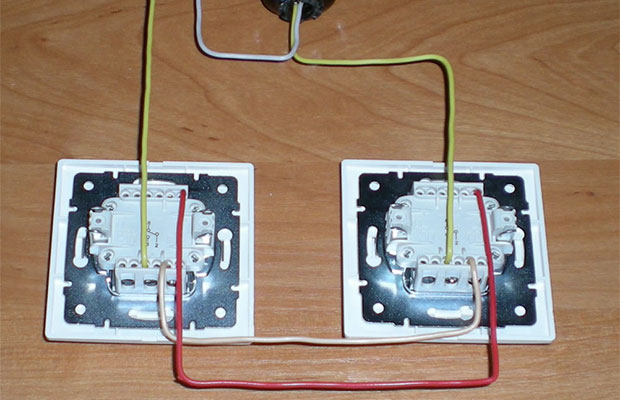
Two lamps per switch
The diagram for connecting two lamps to one switch is similar to the rules for connecting one lamp. The neutral conductor is sequentially directed from the junction box through all lighting sources. The phase wire running through the switch is connected to the second contacts of the light bulbs.
The contacts must be connected as securely as possible. It is recommended to use terminal blocks. Connections are made with screws or Wago blocks (the conductor is pressed with a spring).
Note! It is unacceptable to twist wires of different metals (copper and aluminum). Otherwise, the result of such actions will be an oxidation process, which will lead to loosening of the contact and overheating.
The diagram below shows the connection of two light bulbs to a single-key switch.

Each light source has a marking indicating the load limit. This information must be kept in mind when calculating the total power of connected lighting fixtures.
Two-gang switch
Two-key switches are used in rooms with separate lighting, when you need to connect a chandelier with several arms. Such switches are used in separate units (installed between the doors to the bathroom and toilet).
A two-key switch has a more compact size compared to two single-key switches, so its installation is justified in all cases where you need to save space on the wall.
Separate lighting
A similar scheme is often used in office buildings, where it is necessary to separately illuminate many local areas. The separate lighting scheme is not particularly complicated, although it requires special knowledge.

The switch is placed in a phase break. The devices are equipped with one input and two output voltage contacts. The phase wires after the switch go to the lighting fixtures. The neutral conductor will be common to all light sources in the room.
As a result, pressing one of the keys turns on only the devices connected to a specific phase. Other light sources do not turn on.
Chandelier with multiple arms
To connect a multi-lane lighting device using a two-key switch, you will need a three-wire conductor. One core is shortened so that it goes into the junction box, and a couple of other wires should reach the switch.
The phase wire is directed to the breaker. The outgoing conductors are fixed in the terminal blocks of the switch. The lighting device comes with an output of three wires: neutral and two phase. The zero from the distribution box is directed to the zero contact, and the outgoing wires from the switch are connected to the phases of a multi-arm chandelier.
The connection diagram for a chandelier with five arms is shown in the figure below.

The result is a connection where pressing one key turns on only a pair of lamps. Another key controls three lamps. If you want to turn on all the lights, you must press both keys. Ultimately, this design provides a choice of three light intensity options: with two, three or five bulbs.
In retail chains there are switches with three keys. Their connection diagram is a little more complicated, but generally similar to those given earlier.
Connection from an outlet
In some cases, you need to connect an additional lighting fixture with a dedicated switch. In such a situation, connecting from an existing outlet will do.

When installing a single-key switch, you will need a two-wire wire and a switching device. For a voltage breaker installed above the socket, zero and phase are removed from it. The phase wire is interrupted inside the switch, and the neutral wire is left intact. Other lighting devices in the circuit are provided with power in a similar way to the above circuits.
For electrical installation work, you will need three wires (zero and two phases). For a three-key switch, one more phase core is required.
Connecting lamps with converter
To organize lighting for point consumers, you can use 220-volt networks or 12-volt converters. The latter create a switch-on delay of several seconds, after which they smoothly transfer current to electrical appliances.
The circuit allows you to take care of incandescent lamps or halogen light sources, since it protects them from voltage surges.
The connection diagram is shown in the figure below.

If a converter is used, the switch is installed before it. There are two important technological reasons for this:
- Reduced voltage is associated with significant current. Breakers are not designed for this mode of operation, as a result of which the contacts may burn out.
- The converter allows you to turn on the lamp smoothly. If you place a breaker after the converter, it will not be possible to ensure a smooth start, and the electricity will flow intermittently after pressing a key.
If you are installing a switch with two keys, you will need a second converter. Its power supply will come from the second line. The neutral conductor will be common.
Electrical installation requires special attention to safety. You should start working only after the network has been de-energized. If you do not have confidence in your abilities and at least basic knowledge of electrical engineering, it is better to seek help from a qualified electrician.
The switching circuit for fluorescent lamps is much more complex than that of incandescent lamps.
Their ignition requires the presence of special starting devices, and the life of the lamp depends on the quality of these devices.
To understand how launch systems work, you must first become familiar with the design of the lighting device itself.
A fluorescent lamp is a gas-discharge light source, the luminous flux of which is formed mainly due to the glow of a phosphor layer applied to the inner surface of the bulb.

When the lamp is turned on, an electronic discharge occurs in the mercury vapor that fills the test tube and the resulting UV radiation affects the phosphor coating. With all this, the frequencies of invisible UV radiation (185 and 253.7 nm) are converted into visible light radiation.
These lamps have low energy consumption and are very popular, especially in industrial premises.
Scheme
When connecting fluorescent lamps, a special starting and regulating technique is used - ballasts. There are 2 types of ballasts: electronic - electronic ballast (electronic ballast) and electromagnetic - electronic ballast (starter and choke).
Connection diagram using electromagnetic ballast or electronic ballast (throttle and starter)
A more common connection diagram for a fluorescent lamp is using an electromagnetic amplifier. This starter circuit.
Operating principle: when the power supply is connected, a discharge appears in the starter and
the bimetallic electrodes are short-circuited, after which the current in the circuit of the electrodes and the starter is limited only by the internal resistance of the inductor, as a result of which the operating current in the lamp increases almost three times and the electrodes of the fluorescent lamp instantly heat up.
At the same time, the bimetallic contacts of the starter cool down and the circuit opens.
At the same time, the choke breaks, thanks to self-induction, creates a triggering high-voltage pulse (up to 1 kV), which leads to a discharge in the gas environment and the lamp lights up. After which the voltage on it will become equal to half of the mains voltage, which will not be enough to re-close the starter electrodes.
When the lamp is on, the starter will not participate in the operating circuit and its contacts will and will remain open.
Main disadvantages
- Compared to a circuit with electronic ballast, electricity consumption is 10-15% higher.
- Long start-up of at least 1 to 3 seconds (depending on lamp wear)
- Inoperability at low ambient temperatures. For example, in winter in an unheated garage.
- The stroboscopic result of a flashing lamp, which has a bad effect on vision, and the parts of machine tools rotating synchronously with the mains frequency appear motionless.
- The sound of the throttle plates humming, growing over time.

Switching diagram with two lamps but one choke. It should be noted that the inductance of the inductor must be sufficient for the power of these two lamps.
It should be noted that in a sequential circuit for connecting two lamps, 127 Volt starters are used; they will not work in a single-lamp circuit, which will require 220 Volt starters

This circuit, where, as you can see, there is no starter or throttle, can be used if the filaments of the lamps have burned out. In this case, the LDS can be ignited using step-up transformer T1 and capacitor C1, which will limit the current flowing through the lamp from a 220-volt network.

This circuit is suitable for the same lamps whose filaments have burned out, but here there is no need for a step-up transformer, which clearly simplifies the design of the device

But such a circuit using a diode rectifier bridge eliminates the flickering of the lamp at the mains frequency, which becomes very noticeable as it ages.

or more difficult

If the starter in your lamp has failed or the lamp is constantly blinking (along with the starter if you look closely under the starter housing) and there is nothing at hand to replace it, you can light the lamp without it - enough for 1-2 seconds. short-circuit the starter contacts or install button S2 (caution of dangerous voltage)

the same case, but for a lamp with a burnt-out filament

Connection diagram using electronic ballast or electronic ballast
An electronic ballast (EPG), unlike an electromagnetic one, supplies the lamps with a high-frequency voltage from 25 to 133 kHz rather than the mains frequency. And this completely eliminates the possibility of lamp flickering noticeable to the eye. The electronic ballast uses a self-oscillator circuit, which includes a transformer and an output stage using transistors.
The switching circuit for fluorescent lamps is much more complex than that of incandescent lamps.
Their ignition requires the presence of special starting devices, and the life of the lamp depends on the quality of these devices.
To understand how launch systems work, you must first become familiar with the design of the lighting device itself.
A fluorescent lamp is a gas-discharge light source, the luminous flux of which is formed mainly due to the glow of a phosphor layer applied to the inner surface of the bulb.
When the lamp is turned on, an electronic discharge occurs in the mercury vapor that fills the test tube and the resulting UV radiation affects the phosphor coating. With all this, the frequencies of invisible UV radiation (185 and 253.7 nm) are converted into visible light radiation.
These lamps have low energy consumption and are very popular, especially in industrial premises.
Scheme
When connecting fluorescent lamps, a special starting and regulating technique is used - ballasts. There are 2 types of ballasts: electronic - electronic ballast (electronic ballast) and electromagnetic - electronic ballast (starter and choke).
Connection diagram using electromagnetic ballast or electronic ballast (throttle and starter)
A more common connection diagram for a fluorescent lamp is using an electromagnetic amplifier. This starter circuit.
Operating principle: when the power supply is connected, a discharge appears in the starter and
the bimetallic electrodes are short-circuited, after which the current in the circuit of the electrodes and the starter is limited only by the internal resistance of the inductor, as a result of which the operating current in the lamp increases almost three times and the electrodes of the fluorescent lamp instantly heat up.
At the same time, the bimetallic contacts of the starter cool down and the circuit opens.
At the same time, the choke breaks, thanks to self-induction, creates a triggering high-voltage pulse (up to 1 kV), which leads to a discharge in the gas environment and the lamp lights up. After which the voltage on it will become equal to half of the mains voltage, which will not be enough to re-close the starter electrodes.
When the lamp is on, the starter will not participate in the operating circuit and its contacts will and will remain open.
Main disadvantages
- Compared to a circuit with electronic ballast, electricity consumption is 10-15% higher.
- Long start-up of at least 1 to 3 seconds (depending on lamp wear)
- Inoperability at low ambient temperatures. For example, in winter in an unheated garage.
- The stroboscopic result of a flashing lamp, which has a bad effect on vision, and the parts of machine tools rotating synchronously with the mains frequency appear motionless.
- The sound of the throttle plates humming, growing over time.
Switching diagram with two lamps but one choke. It should be noted that the inductance of the inductor must be sufficient for the power of these two lamps.
It should be noted that in a sequential circuit for connecting two lamps, 127 Volt starters are used; they will not work in a single-lamp circuit, which will require 220 Volt starters
This circuit, where, as you can see, there is no starter or throttle, can be used if the filaments of the lamps have burned out. In this case, the LDS can be ignited using step-up transformer T1 and capacitor C1, which will limit the current flowing through the lamp from a 220-volt network.
This circuit is suitable for the same lamps whose filaments have burned out, but here there is no need for a step-up transformer, which clearly simplifies the design of the device
But such a circuit using a diode rectifier bridge eliminates the flickering of the lamp at the mains frequency, which becomes very noticeable as it ages.
or more difficult
If the starter in your lamp has failed or the lamp is constantly blinking (along with the starter if you look closely under the starter housing) and there is nothing at hand to replace it, you can light the lamp without it - enough for 1-2 seconds. short-circuit the starter contacts or install button S2 (caution of dangerous voltage)
the same case, but for a lamp with a burnt-out filament
Connection diagram using electronic ballast or electronic ballast
An electronic ballast (EPG), unlike an electromagnetic one, supplies the lamps with a high-frequency voltage from 25 to 133 kHz rather than the mains frequency. And this completely eliminates the possibility of lamp flickering noticeable to the eye. The electronic ballast uses a self-oscillator circuit, which includes a transformer and an output stage using transistors.
Gone are the days when the wiring diagram for electrical appliances, including lamps, was “tailored” to the existing switching devices, taking care of the optimal location of the latter. Currently, there is such a variety of switches, switches, and so on, different in functionality and technical capabilities, that you can safely do the wiring in such a way that turning on and off the electrical appliances used is as convenient as possible for their user. A special case is lighting control from two places (points), that is, a pair of switches.
Options and advantages of using lighting control with two switches
The classic diagram for connecting one lamp (lamp) is known to everyone. You need 1 switch, which is located in the most accessible or convenient place for lighting control: at the beginning or middle of passage rooms, long corridors, galleries, alleys (); at the entrance to the premises or entrance, and so on. Almost everyone has encountered how inconvenient this can be.
And now the same and other options for controlling lighting devices, but using 2 switches:
- In walk-through rooms and premises, as well as buildings with two entrances (garages, sheds, outbuildings for keeping pets or poultry), especially when they are opposite. Installing one switch for each input will eliminate the unpleasant need to walk in the dark to turn on the light or after turning it off. After all, it often happens that you need to enter through one door and exit through another.
- In corridors, galleries, alleys (paths in the garden), etc., especially when they are long, connecting two switches - one at each end of these objects - will ensure not only convenient use of light, but also its saving. After all, it will be possible to use the lighting when moving in any direction and immediately turn it off after passing this section of the path.
- In the entrance of a residential apartment building or on the stairs between the floors of a private two-story building. There are also 2 switches here, both convenient and economical.
- In the bedroom. If you place one switch at the entrance and the other at the head of the bed, you won’t have to get up to turn off the light when it’s time to fall asleep. And vice versa, when you wake up, you can immediately, without getting up, turn on the lighting, and then turn it off only when leaving the bedroom, without returning to the bed. This is especially convenient when the bedroom is large.
- And in many other cases, when there is a need to control one lighting fixture from two places.

As you can see from the examples, 2 switches are not only very convenient, but also save energy, that is, ultimately, money. After all, the light can be turned off as soon as it is no longer needed. And it does not need to be left all night, as was the case with the 1st switch, for example, in long corridors, when returning to their beginning to de-energize the lamps did not make sense. After all, the light was turned on to go through this corridor.
What switches are needed to control the light from two points - name and design
The considered use of two switches assumes that, regardless of the position of the switching contacts of one of them, the other can always turn the lighting on or off at any time. Conventional switches, which humanity has used since the invention of electricity, are completely unsuitable for this. After all, they are not initially structurally designed for such work, because in one of their two positions they open (break) the electrical circuit. Therefore, no matter how you connect them, it doesn’t matter if one of them has open contacts, the other will never turn on the electrical appliance. And they must be connected somehow to each other, since it is assumed that they will be used to control the operation of the same lamp, that is, installed as part of one common electrical circuit.
To independently control lighting and other electrical appliances from two places, so-called pass-through switches, which have recently appeared on the market of electrical products, are used.
They are also called pass-through switches or changeover switches and switches. And there are also cross switches, but these are slightly different and more complex devices, used in conjunction with pass-through switches to control electrical appliances from three or more points. They can be installed instead of walk-throughs, but they will cost more, but vice versa cannot be changed. Externally, from the front side, these switches are no different from ordinary switches. The same body and 1 or 2 keys (sometimes a different type of control part) for turning on and off.
Externally, a pass-through switch differs from a regular switch in the following: on the back of the case, where they are connected, it has 3 terminals for them. That is, 3 conductors are connected to the pass-through switch. A regular switch has only 2 terminals (a cross switch has 4). This is if the switching device is single-key.
If you need to control 2 groups of lamps of one lamp, that is, you will need two-key (double) pass-through switches, then you need to look for devices with six terminals for the connected wiring. Dual conventional switches have only 3 terminals (crossover switches have 8).
And now about the internal design differences and the resulting differences in work. The circuit supplied to the pass-through switch leaves it along 2 lines, between which it switches. That is, in each of its 2 positions, this switch closes one line coming out of it and breaks the second. It turns out that he never breaks the chain passing through him. How this works in practice and provides independent control of 1 electrical appliance using 2-pass switches is discussed in the next chapter and is clearly visible in the diagrams given therein.
Connection diagrams and operating principle of two pass-through switches in one circuit
There is only one way to connect two pass-through switches to switch one lighting or some other electrical appliance or several connected in series, that is, combined into one group. So it's impossible to go wrong with this. Below is a wiring diagram for one lamp.

In this typical diagram it can be seen that pass-through switches are connected in series one after another in a circuit break between the electricity consumer and the phase. Moreover, they must be connected by 2 wires. In the following diagram of two switches for one light bulb, you can more clearly examine the operation of the entire circuit as a whole.

In the previous figure, the electrical appliance was turned on, and in this one it was turned off with switch No. 2. Obviously, the same action could have been done with switch No. 1. And from the current position of the switches it is clear that any of them can again power the electrical appliance.
It is very simple to assemble such a circuit. For switches, exactly as shown in the figures, the input (common) terminal for phase or zero is located on one side of the housing, and 2 output terminals are on the other. So, feel free to connect them, in any order, with 2 wires to each other. And then, to the already connected switches, we connect the rest of the wiring: to one of them, to which the zero is connected, and to the other - the phases. Since all electrical devices must be connected through a junction box, below is a diagram of the correct assembly of the entire circuit using it.

To turn 2 groups of electrical appliances on and off, you will need dual (with two keys) pass-through switches. The following diagram is just for such a circuit, assembled using a junction box.

It is clearly visible in the figure and in the comments to it it is written that pass-through switches of 2 different modifications will be required - one with a phase connection from above, and the other from below. Despite its apparent complexity, this circuit is quite simple to make. On the switches, exactly as shown in the figure, there are arrow-shaped marks that tell you which wire goes where.


