Period of electromagnetic oscillations. Oscillatory circuit. Free electromagnetic oscillations. Conversion of energy in an oscillatory circuit. Thompson's formula. Processes in an oscillatory circuit
Thomson's formula named after the English physicist William Thomson, who derived it in 1853, and connects the period of natural electrical or electromagnetic oscillations in a circuit with its capacitance and inductance.Thomson's formula is as follows:
see also
Write a review about the article "Thomson's Formula"
Notes
Excerpt characterizing Thomson's Formula
- Yes, yes, I know. Let’s go, let’s go...” said Pierre and entered the house. A tall, bald old man in a dressing gown, with a red nose, and galoshes on his bare feet, stood in the hallway; Seeing Pierre, he muttered something angrily and went into the corridor.“They were of great intelligence, but now, as you can see, they have weakened,” said Gerasim. - Would you like to go to the office? – Pierre nodded his head. – The office was sealed and remains so. Sofya Danilovna ordered that if they come from you, then release the books.
Pierre entered the same gloomy office that he had entered with such trepidation during the life of his benefactor. This office, now dusty and untouched since the death of Joseph Alekseevich, was even gloomier.
Gerasim opened one shutter and tiptoed out of the room. Pierre walked around the office, went to the cabinet in which the manuscripts lay, and took out one of the once most important shrines of the order. These were genuine Scottish deeds with notes and explanations from the benefactor. He sat down at a dusty desk and put the manuscripts in front of him, opened them, closed them, and finally, moving them away from him, leaning his head on his hands, began to think.
Topics of the Unified State Examination codifier: free electromagnetic oscillations, oscillatory circuit, forced electromagnetic oscillations, resonance, harmonic electromagnetic oscillations.
Electromagnetic vibrations- These are periodic changes in charge, current and voltage that occur in an electrical circuit. The simplest system for observing electromagnetic oscillations is an oscillatory circuit.
Oscillatory circuit
Oscillatory circuit is a closed circuit formed by a capacitor and a coil connected in series.
Let's charge the capacitor, connect the coil to it and close the circuit. Will start to happen free electromagnetic oscillations- periodic changes in the charge on the capacitor and the current in the coil. Let us remember that these oscillations are called free because they occur without any external influence - only due to the energy stored in the circuit.
The period of oscillations in the circuit will be denoted, as always, by . We will assume the coil resistance to be zero.
Let us consider in detail all the important stages of the oscillation process. For greater clarity, we will draw an analogy with the oscillations of a horizontal spring pendulum.
Starting moment: . The capacitor charge is equal to , there is no current through the coil (Fig. 1). The capacitor will now begin to discharge.

Rice. 1.
Even though the coil resistance is zero, the current will not increase instantly. As soon as the current begins to increase, a self-induction emf will arise in the coil, preventing the current from increasing.
Analogy. The pendulum is pulled to the right by an amount and released at the initial moment. The initial speed of the pendulum is zero.
First quarter of the period: . The capacitor is discharging, its charge is currently equal to . The current through the coil increases (Fig. 2).

Rice. 2.
The current increases gradually: the vortex electric field of the coil prevents the current from increasing and is directed against the current.
Analogy. The pendulum moves to the left towards the equilibrium position; the speed of the pendulum gradually increases. The deformation of the spring (aka the coordinate of the pendulum) decreases.
End of first quarter: . The capacitor is completely discharged. The current strength has reached its maximum value (Fig. 3). The capacitor will now begin recharging.

Rice. 3.
The voltage across the coil is zero, but the current will not disappear instantly. As soon as the current begins to decrease, a self-induction emf will arise in the coil, preventing the current from decreasing.
Analogy. The pendulum passes through its equilibrium position. Its speed reaches its maximum value. The spring deformation is zero.
Second quarter: . The capacitor is recharged - a charge of the opposite sign appears on its plates compared to what it was at the beginning (Fig. 4).

Rice. 4.
The current strength decreases gradually: the eddy electric field of the coil, supporting the decreasing current, is co-directed with the current.
Analogy. The pendulum continues to move to the left - from the equilibrium position to the right extreme point. Its speed gradually decreases, the deformation of the spring increases.
End of second quarter. The capacitor is completely recharged, its charge is again equal (but the polarity is different). The current strength is zero (Fig. 5). Now the reverse recharging of the capacitor will begin.

Rice. 5.
Analogy. The pendulum has reached the far right point. The speed of the pendulum is zero. The spring deformation is maximum and equal to .
Third quarter: . The second half of the oscillation period began; processes went in the opposite direction. The capacitor is discharged (Fig. 6).

Rice. 6.
Analogy. The pendulum moves back: from the right extreme point to the equilibrium position.
End of the third quarter: . The capacitor is completely discharged. The current is maximum and again equal to , but this time it has a different direction (Fig. 7).

Rice. 7.
Analogy. The pendulum again passes through the equilibrium position at maximum speed, but this time in the opposite direction.
Fourth quarter: . The current decreases, the capacitor charges (Fig. 8).

Rice. 8.
Analogy. The pendulum continues to move to the right - from the equilibrium position to the extreme left point.
End of the fourth quarter and the entire period: . The reverse recharging of the capacitor is completed, the current is zero (Fig. 9).

Rice. 9.
This moment is identical to the moment, and this figure is identical to Figure 1. One complete oscillation took place. Now the next oscillation will begin, during which the processes will occur exactly as described above.
Analogy. The pendulum returned to its original position.
The considered electromagnetic oscillations are undamped- they will continue indefinitely. After all, we assumed that the coil resistance is zero!
In the same way, the oscillations of a spring pendulum will be undamped in the absence of friction.
In reality, the coil has some resistance. Therefore, the oscillations in a real oscillatory circuit will be damped. So, after one complete oscillation, the charge on the capacitor will be less than the original value. Over time, the oscillations will completely disappear: all the energy initially stored in the circuit will be released in the form of heat at the resistance of the coil and connecting wires.
In the same way, the oscillations of a real spring pendulum will be damped: all the energy of the pendulum will gradually turn into heat due to the inevitable presence of friction.
Energy transformations in an oscillatory circuit
We continue to consider undamped oscillations in the circuit, considering the coil resistance to be zero. The capacitor has a capacitance and the inductance of the coil is equal to .
Since there are no heat losses, energy does not leave the circuit: it is constantly redistributed between the capacitor and the coil.
Let's take a moment in time when the charge of the capacitor is maximum and equal to , and there is no current. The energy of the magnetic field of the coil at this moment is zero. All the energy of the circuit is concentrated in the capacitor:
Now, on the contrary, let’s consider the moment when the current is maximum and equal to , and the capacitor is discharged. The energy of the capacitor is zero. All the circuit energy is stored in the coil:
At an arbitrary moment in time, when the charge of the capacitor is equal and current flows through the coil, the energy of the circuit is equal to:
Thus,
(1)
Relationship (1) is used to solve many problems.
Electromechanical analogies
In the previous leaflet about self-induction, we noted the analogy between inductance and mass. Now we can establish several more correspondences between electrodynamic and mechanical quantities.
For a spring pendulum we have a relationship similar to (1):
(2)
Here, as you already understood, is the spring stiffness, is the mass of the pendulum, and is the current values of the coordinates and speed of the pendulum, and is their greatest values.
Comparing equalities (1) and (2) with each other, we see the following correspondences:
(3)
(4)
(5)
(6)
Based on these electromechanical analogies, we can foresee a formula for the period of electromagnetic oscillations in an oscillatory circuit.
In fact, the period of oscillation of a spring pendulum, as we know, is equal to:
In accordance with analogies (5) and (6), here we replace mass with inductance, and stiffness with inverse capacitance. We get:
(7)
Electromechanical analogies do not fail: formula (7) gives the correct expression for the period of oscillations in the oscillatory circuit. It is called Thomson's formula. We will present its more rigorous conclusion shortly.
Harmonic law of oscillations in a circuit
Recall that oscillations are called harmonic, if the oscillating quantity changes over time according to the law of sine or cosine. If you have forgotten these things, be sure to repeat the “Mechanical Vibrations” sheet.
The oscillations of the charge on the capacitor and the current in the circuit turn out to be harmonic. We will prove this now. But first we need to establish rules for choosing the sign for the capacitor charge and for the current strength - after all, when oscillating, these quantities will take on both positive and negative values.
First we choose positive bypass direction contour. The choice does not matter; let this be the direction counterclock-wise(Fig. 10).

Rice. 10. Positive bypass direction
The current strength is considered positive class="tex" alt="(I > 0)"> , если ток течёт в положительном направлении. В противном случае сила тока будет отрицательной .!}
The charge on a capacitor is the charge on its plate to which positive current flows (i.e., the plate to which the bypass direction arrow points). In this case - charge left capacitor plates.
With such a choice of signs of current and charge, the following relation is valid: (with a different choice of signs it could happen). Indeed, the signs of both parts coincide: if class="tex" alt="I > 0"> , то заряд левой пластины возрастает, и потому !} class="tex" alt="\dot(q) > 0"> !}.
The quantities and change over time, but the energy of the circuit remains unchanged:
(8)
Therefore, the derivative of energy with respect to time becomes zero: . We take the time derivative of both sides of relation (8); do not forget that complex functions are differentiated on the left (If is a function of , then according to the rule of differentiation of complex functions, the derivative of the square of our function will be equal to: ):
Substituting and here, we get:
But the current strength is not a function that is identically equal to zero; That's why
Let's rewrite this as:
(9)
We have obtained a differential equation of harmonic oscillations of the form , where . This proves that the charge on the capacitor oscillates according to a harmonic law (i.e., according to the law of sine or cosine). The cyclic frequency of these oscillations is equal to:
(10)
This quantity is also called natural frequency contour; It is with this frequency that free (or, as they also say, own fluctuations). The oscillation period is equal to:
We again come to Thomson's formula.
The harmonic dependence of charge on time in the general case has the form:
(11)
The cyclic frequency is found by formula (10); the amplitude and initial phase are determined from the initial conditions.
We will look at the situation discussed in detail at the beginning of this leaflet. Let the charge of the capacitor be maximum and equal (as in Fig. 1); there is no current in the circuit. Then the initial phase is , so that the charge varies according to the cosine law with amplitude:
(12)
Let's find the law of change in current strength. To do this, we differentiate relation (12) with respect to time, again not forgetting about the rule for finding the derivative of a complex function:
We see that the current strength also changes according to a harmonic law, this time according to the sine law:
(13)
The amplitude of the current is:
The presence of a “minus” in the law of current change (13) is not difficult to understand. Let's take, for example, a time interval (Fig. 2).
The current flows in the negative direction: . Since , the oscillation phase is in the first quarter: . The sine in the first quarter is positive; therefore, the sine in (13) will be positive on the time interval under consideration. Therefore, to ensure that the current is negative, the minus sign in formula (13) is really necessary.
Now look at fig. 8 . The current flows in the positive direction. How does our “minus” work in this case? Figure out what's going on here!
Let us depict graphs of charge and current fluctuations, i.e. graphs of functions (12) and (13). For clarity, let us present these graphs in the same coordinate axes (Fig. 11).

Rice. 11. Graphs of charge and current fluctuations
Please note: charge zeros occur at current maxima or minima; conversely, current zeros correspond to charge maxima or minima.
Using the reduction formula
Let us write the law of current change (13) in the form:
Comparing this expression with the law of charge change, we see that the current phase, equal to, is greater than the charge phase by an amount. In this case they say that the current ahead in phase charge on ; or phase shift between current and charge is equal to ; or phase difference between current and charge is equal to .
The advance of the charge current in phase is graphically manifested in the fact that the current graph is shifted left on relative to the charge graph. The current strength reaches, for example, its maximum a quarter of a period earlier than the charge reaches its maximum (and a quarter of a period exactly corresponds to the phase difference).
Forced electromagnetic oscillations
As you remember, forced oscillations arise in the system under the influence of a periodic forcing force. The frequency of forced oscillations coincides with the frequency of the driving force.
Forced electromagnetic oscillations will occur in a circuit connected to a sinusoidal voltage source (Fig. 12).

Rice. 12. Forced vibrations
If the source voltage changes according to the law:
then oscillations of charge and current occur in the circuit with a cyclic frequency (and with a period, respectively). The AC voltage source seems to “impose” its oscillation frequency on the circuit, making you forget about its own frequency.
The amplitude of forced oscillations of charge and current depends on frequency: the amplitude is greater, the closer to the natural frequency of the circuit. When resonance- a sharp increase in the amplitude of oscillations. We'll talk about resonance in more detail in the next worksheet on alternating current.
Lesson No. 48-169 Oscillatory circuit. Free electromagnetic oscillations. Conversion of energy in an oscillatory circuit. Thompson's formula.Oscillations- movements or states that repeat over time.Electromagnetic vibrations -these are electrical vibrations andmagnetic fields that resistdriven by periodic infidelitycharge, current and voltage. An oscillatory circuit is a system consisting of an inductor and a capacitor(Fig. a). If the capacitor is charged and shorted to the coil, then current will flow through the coil (Fig. b). When the capacitor is discharged, the current in the circuit will not stop due to self-induction in the coil. The induction current, in accordance with Lenz's rule, will flow in the same direction and recharge the capacitor (Fig. c). The current in this direction will stop, and the process will repeat in the opposite direction (Fig. G).
Thus, in fluctuationstelny contour of the originelectromagnetic oscillationsnia due to energy conversionelectric field condensationra( W E = 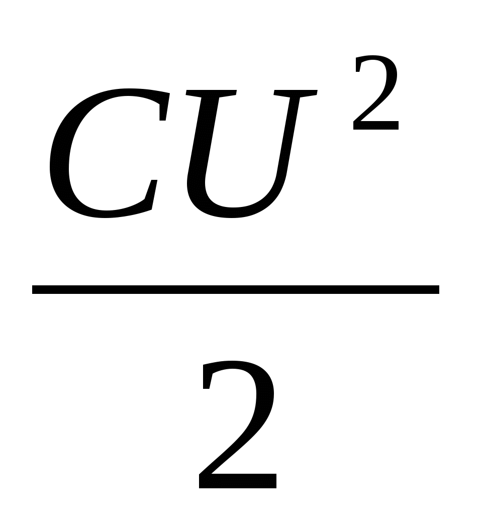 )
into the energy of the magnetic field of a coil with current(W M =
 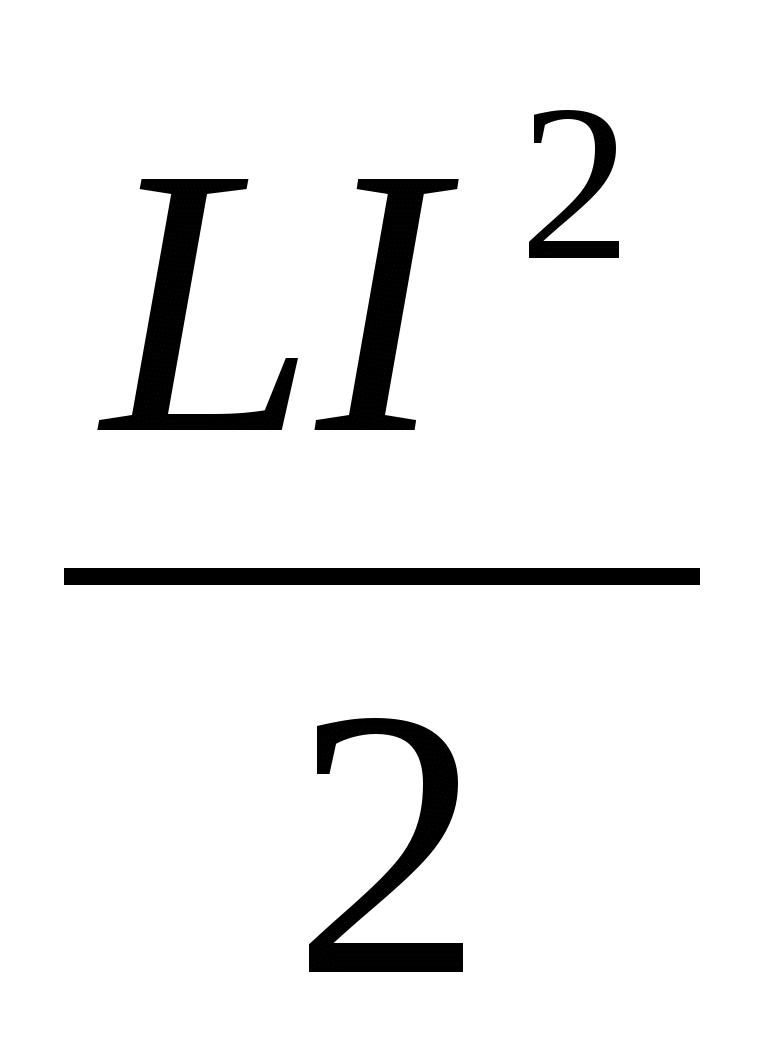 ),
and vice versa.
Harmonic oscillations are periodic changes in a physical quantity depending on time, occurring according to the law of sine or cosine.
 The equation describing free electromagnetic oscillations takes the form
q"= - ω 0 2 q (q" is the second derivative.
Main characteristics of oscillatory motion:
The period of oscillation is the minimum period of time T after which the process is completely repeated.
The amplitude of harmonic oscillations is the modulus of the largest value of the oscillating quantity.
Knowing the period, you can determine the frequency of oscillations, i.e. the number of oscillations per unit of time, for example per second. If one oscillation occurs in time T, then the number of oscillations in 1 s ν is determined as follows: ν = 1/T.
Recall that in the International System of Units (SI), the frequency of oscillations is equal to one if one oscillation occurs in 1 s. The unit of frequency is called the hertz (abbreviated: Hz) after the German physicist Heinrich Hertz.
After a period of time equal to the period T, i.e., when the cosine argument increases by ω 0
T, the charge value is repeated and the cosine takes on its previous value. From the mathematics course we know that the smallest period of the cosine is 2n. Therefore, ω 0
T=2π, whence ω 0
= 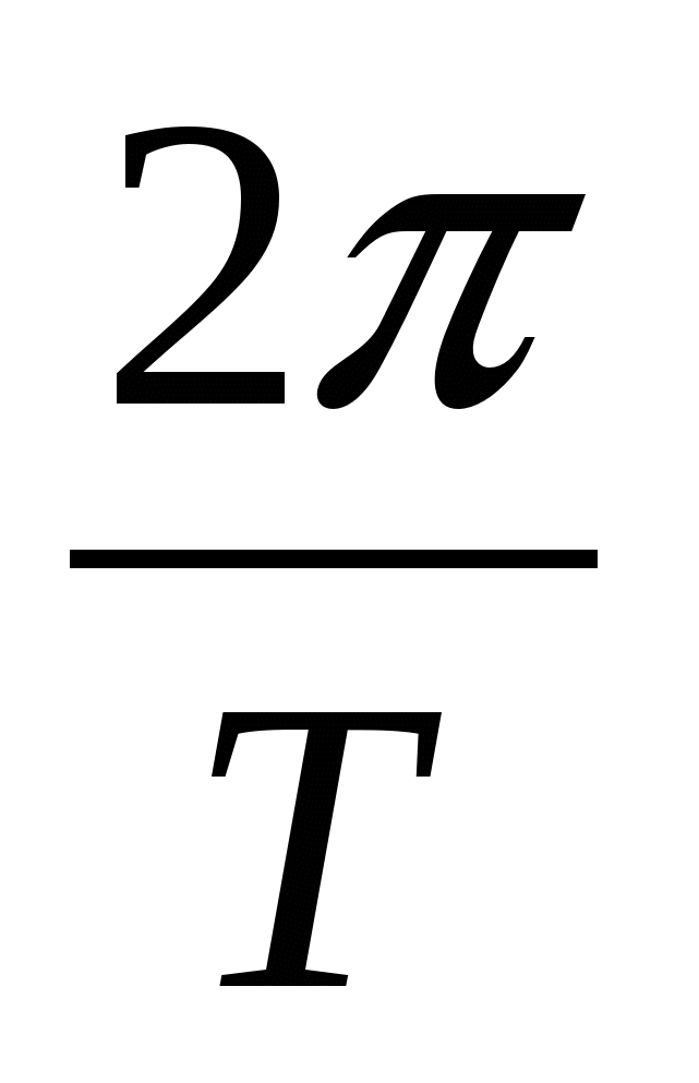 =2πν Thus, the value ω 0
- this is the number of oscillations, but not in 1 s, but in 2 s. It is called cyclical or circular frequency.
The frequency of free oscillations is called natural vibrational frequencysystems. Often in the following, for brevity, we will simply refer to the cyclic frequency as frequency. Distinguish cyclic frequency ω 0 from frequency ν can be used according to the notation.
By analogy with the solution of the differential equation for a mechanical oscillatory system cyclic frequency of free electricitysky fluctuations is equal to:ω 0 = 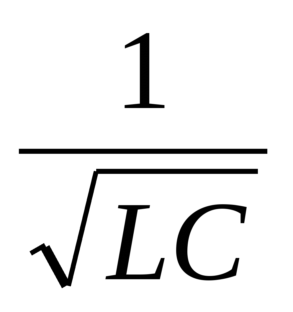
The period of free oscillations in the circuit is equal to: T=  =2π
=2π  - Thomson's formula.
The phase of oscillations (from the Greek word phasis - appearance, stage of development of a phenomenon) is the value of φ, standing under the sign of cosine or sine. The phase is expressed in angular units - radians. The phase determines, for a given amplitude, the state of the oscillatory system at any time.
Oscillations with the same amplitudes and frequencies may differ from each other in phases.
Since ω 0
= , then φ= ω 0
Т=2π . The ratio shows how much of the period has passed since the start of the oscillation. Any time value expressed in fractions of a period corresponds to a phase value expressed in radians. So, after time t=
  (quarter period) φ=
 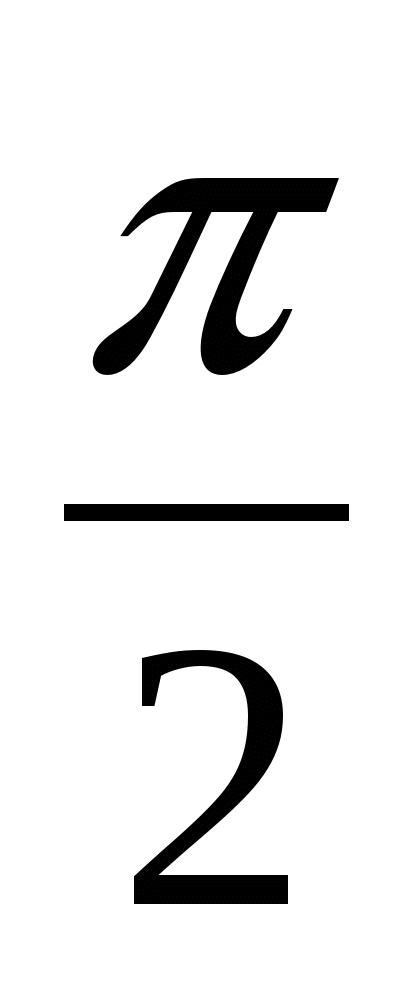 , after half the period φ = π, after the whole period φ = 2π, etc. You can plot the dependence
 charge does not depend on time, but on phase. The figure shows the same cosine wave as the previous one, but on the horizontal axis they are plotted instead of time
different phase values φ.
Correspondence between mechanical and electrical quantities in oscillatory processes
Mechanical quantities
Tasks.942(932). The initial charge imparted to the capacitor of the oscillatory circuit was reduced by 2 times. How many times did: a) voltage amplitude change; b) current amplitude;
c) the total energy of the electric field of the capacitor and the magnetic field of the coil?
943(933). With an increase in the voltage on the capacitor of the oscillating circuit by 20 V, the amplitude of the current increased by 2 times. Find the initial voltage.
945(935). The oscillatory circuit consists of a capacitor with a capacity C = 400 pF and an inductance coil L = 10 mH. Find the amplitude of current oscillations I T , if the amplitude of voltage fluctuations U T = 500 V.
952(942). After what time (in fractions of the period t/T) for the first time there will be a charge on the capacitor of the oscillating circuit equal to half the amplitude value?
957(947). What inductance coil should be included in the oscillatory circuit in order to obtain a free oscillation frequency of 10 MHz with a capacitor capacitance of 50 pF?
Oscillatory circuit. Period of free oscillations.
1. After the capacitor of the oscillating circuit has been given a charge q = 10 -5 C, damped oscillations arose in the circuit. How much heat will be released in the circuit by the time the oscillations in it completely die out? Capacitance of the capacitor C = 0.01 μF.
2. The oscillating circuit consists of a capacitor with a capacity of 400 nF and a coil with an inductance of 9 μH. What is the period of natural oscillation of the circuit?
3. What inductance must be included in the oscillatory circuit in order to obtain a natural oscillation period of 2∙ 10 -6 s with a capacitance of 100 pF.
4. Compare spring stiffness k1/k2 of two pendulums with load masses of 200g and 400g, respectively, if their periods of oscillation are equal.
5. Under the action of a stationary load hanging on a spring, its elongation was equal to 6.4 cm. Then the weight was pulled back and released, as a result of which it began to oscillate. Determine the period of these oscillations.
6. A load was suspended from a spring, brought out of its equilibrium position and released. The load began to oscillate with a period of 0.5 s. Determine the elongation of the spring after the oscillations stop. Ignore the mass of the spring.
7. During the same time, one mathematical pendulum makes 25 oscillations, and the other 15. Find their lengths if one of them is 10 cm shorter than the other.8. The oscillatory circuit consists of a capacitor with a capacity of 10 mF and an inductor of 100 mH. Find the amplitude of voltage fluctuations if the amplitude of current fluctuations is 0.1A9. The inductance of the oscillating circuit coil is 0.5 mH. It is required to configure this circuit to a frequency of 1 MHz. What should be the capacitance of the capacitor in this circuit?Exam questions:
1. Which of the following expressions determines the period of free oscillations in an oscillatory circuit? A.; B.  ; IN.
; IN.  ; G.
; G.  ; D. 2 .
2 . Which of the following expressions determines the cyclic frequency of free oscillations in an oscillatory circuit? A.B.
  IN.
IN. 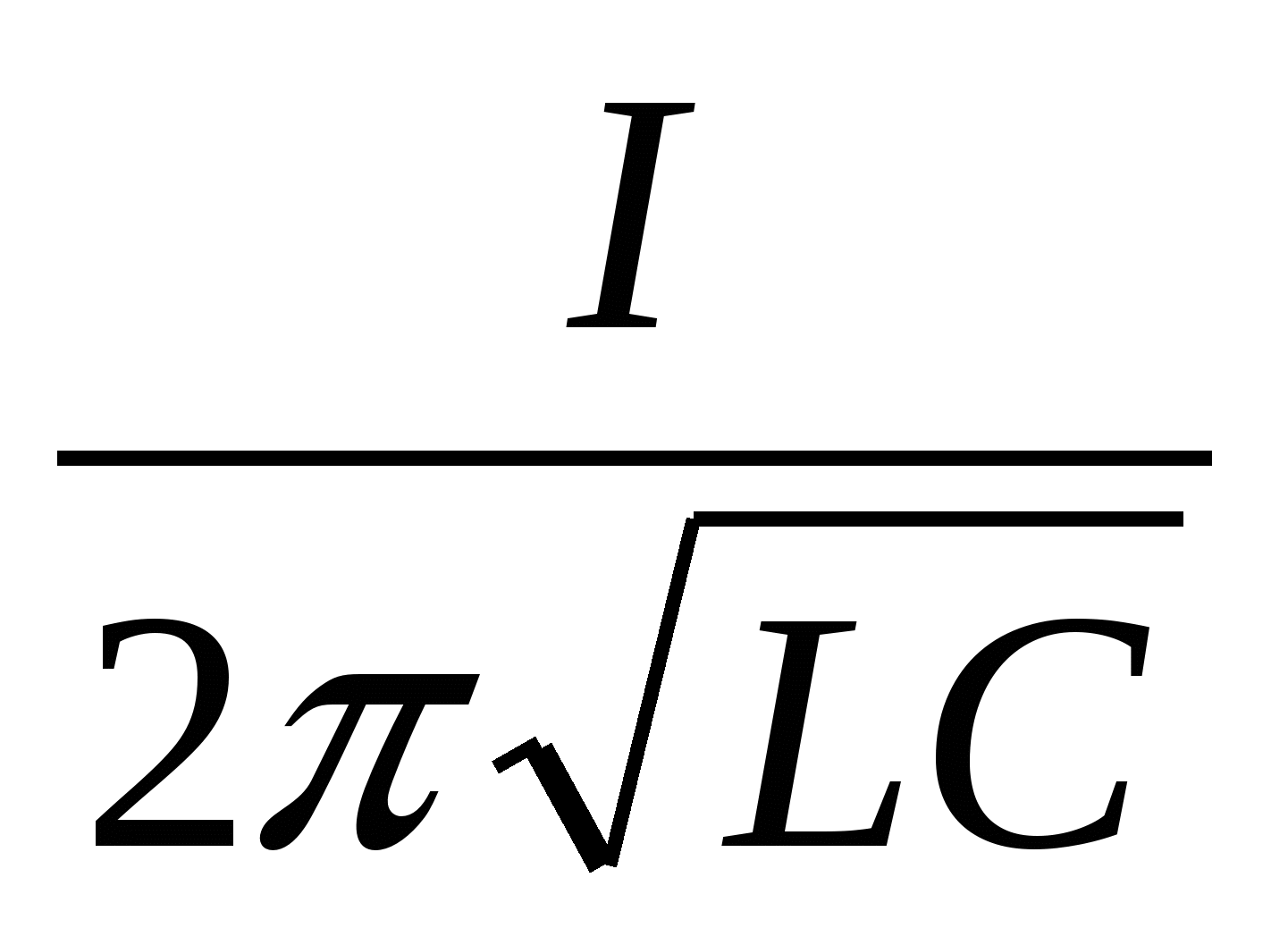 G.
G.  D. 2π
D. 2π
3. The figure shows a graph of the X coordinate of a body performing harmonic oscillations along the x axis as a function of time. What is the period of vibration of the body?
A. 1 s; B. 2 s; V. 3 s . G. 4 p.
4. The figure shows the wave profile at a certain point in time. What is its length?
A. 0.1 m. B. 0.2 m. C. 2 m. D. 4 m. D. 5 m.5
 . The figure shows a graph of the current through the oscillating circuit coil versus time. What is the period of current oscillation? A. 0.4 s. B. 0.3 s. V. 0.2 s. G. 0.1 s.
 D. There is no correct answer among answers A-D.

6. The figure shows the wave profile at a certain point in time. What is its length?
A. 0.2 m. B. 0.4 m. C. 4 m. D. 8 m. D. 12 m.
7. Electrical vibrations in the oscillatory circuit are given by the equation q =10 -2 ∙ cos 20t (Cl).
What is the amplitude of charge oscillations?
A . 10 -2 Cl. B.cos 20t Cl. B.20t Cl. G.20 Cl. D. Among the answers A-D there is no correct one.
8. During harmonic vibrations along the OX axis, the coordinate of the body changes according to the law X=0.2cos(5t+  ). What is the amplitude of the body's vibrations?
A. Xm; B. 0.2 m; V. сos(5t+) m; (5t+)m; D.m
9. Oscillation frequency of the wave source is 0.2 s -1 wave propagation speed is 10 m/s. What is the wavelength? A. 0.02 m. B. 2 m. C. 50 m.
D. According to the conditions of the problem, it is impossible to determine the wavelength. D. There is no correct answer among answers A-D.
10. Wave length 40 m, propagation speed 20 m/s. What is the oscillation frequency of the wave source?
A. 0.5 s -1 . B. 2 s -1 . V. 800 s -1 .
D. According to the conditions of the problem, it is impossible to determine the oscillation frequency of the wave source.
D. There is no correct answer among answers A-D.
3
The main device that determines the operating frequency of any alternating current generator is the oscillating circuit. The oscillatory circuit (Fig. 1) consists of an inductor L(consider the ideal case when the coil has no ohmic resistance) and a capacitor C and is called closed. The characteristic of a coil is inductance, it is designated L and measured in Henry (H), the capacitor is characterized by capacitance C, which is measured in farads (F).
Let at the initial moment of time the capacitor be charged in such a way (Fig. 1) that on one of its plates there is a charge + Q 0, and on the other - charge - Q 0 . In this case, an electric field with energy is formed between the plates of the capacitor
where is the amplitude (maximum) voltage or potential difference across the capacitor plates.
After closing the circuit, the capacitor begins to discharge and an electric current flows through the circuit (Fig. 2), the value of which increases from zero to the maximum value. Since a current of variable magnitude flows in the circuit, a self-inductive emf is induced in the coil, which prevents the capacitor from discharging. Therefore, the process of discharging the capacitor does not occur instantly, but gradually. At each moment of time, the potential difference across the capacitor plates
(where is the charge of the capacitor at a given time) is equal to the potential difference across the coil, i.e. equal to the self-induction emf
 |
 |
| Fig.1 | Fig.2 |
When the capacitor is completely discharged and , the current in the coil will reach its maximum value (Fig. 3). The induction of the magnetic field of the coil at this moment is also maximum, and the energy of the magnetic field will be equal to
Then the current begins to decrease, and the charge will accumulate on the capacitor plates (Fig. 4). When the current decreases to zero, the capacitor charge reaches its maximum value Q 0, but the plate, previously positively charged, will now be negatively charged (Fig. 5). Then the capacitor begins to discharge again, and the current in the circuit flows in the opposite direction.
So the process of charge flowing from one capacitor plate to another through the inductor is repeated again and again. They say that in the circuit there are electromagnetic vibrations. This process is associated not only with fluctuations in the amount of charge and voltage on the capacitor, the current strength in the coil, but also with the transfer of energy from the electric field to the magnetic field and vice versa.
 |
 |
| Fig.3 | Fig.4 |
Recharging the capacitor to the maximum voltage will occur only if there is no energy loss in the oscillating circuit. Such a contour is called ideal.
In real circuits the following energy losses occur:
1) heat losses, because R ¹ 0;
2) losses in the dielectric of the capacitor;
3) hysteresis losses in the coil core;
4) radiation losses, etc. If we neglect these energy losses, then we can write that, i.e.
Oscillations occurring in an ideal oscillatory circuit in which this condition is met are called free, or own, circuit vibrations.
In this case the voltage U(and charge Q) on the capacitor changes according to the harmonic law:
where n is the natural frequency of the oscillatory circuit, w 0 = 2pn is the natural (circular) frequency of the oscillatory circuit. The frequency of electromagnetic oscillations in the circuit is defined as
Period T- the time during which one complete oscillation of the voltage on the capacitor and the current in the circuit occurs is determined Thomson's formula
The current strength in the circuit also changes according to the harmonic law, but lags behind the voltage in phase by . Therefore, the dependence of the current in the circuit on time will have the form
![]() . (9)
. (9)
Figure 6 shows graphs of voltage changes U on the capacitor and current I in the coil for an ideal oscillating circuit.
In a real circuit, the energy will decrease with each oscillation. The amplitudes of the voltage on the capacitor and the current in the circuit will decrease; such oscillations are called damped. They cannot be used in master oscillators, because The device will work at best in pulse mode.
 |
 |
| Fig.5 | Fig.6 |
To obtain undamped oscillations, it is necessary to compensate for energy losses at a wide variety of operating frequencies of devices, including those used in medicine.


