How to choose a trim resistor. Variable resistor, potentiometer, resistance, controlled, adjustable, voltage changeable. Adjustment, control. Manage, regulate, change. Features of trimming resistors
Variable and tuning resistors. Rheostat. Variable resistor in the diagram
operating principle. How to connect a variable resistor? :: SYL.ru
A large number of people turn to radio stores to do something with their own hands. The main task of those who like to collect radios and circuits is to create useful items that will benefit not only themselves, but also those around them. A variable resistor helps to carry out repairs or create a device that operates from an electrical network.
Basic properties of variable resistors
When a person has a clear idea of the conventional elements of graphic display on diagrams, then he has the problem of transferring the drawing into reality. You need to find or purchase individual components of a ready-made circuit. Today there are a large number of stores that sell the necessary parts. You can also find elements in old broken radio equipment.
A variable resistor must be present in any circuit. It is found in any electronic devices. This design is a cylinder that includes diametrically opposed terminals. The resistor creates a limit on the flow of current in the circuit. If necessary, it will perform resistance, which can be measured in ohms. A variable resistor is indicated on the diagram in the form of a rectangle along with two dashes. They are located on opposite sides inside the rectangle. Thus, a person denotes power on his diagram.
The equipment, which is found in almost every home, includes resistors with a certain value. They are located along the E24 row and conventionally indicate the range from one to ten.
Types of resistors
Today there are a large number of resistors that are found in modern household electrical appliances. The following types can be distinguished:
- Heat-resistant varnished metal resistor. It can be found in lamp devices that have a power of at least 0.5 watts. In Soviet equipment you can find resistors such as those produced in the early 80s. They have different powers, which directly depend on the size and dimensions of the radio equipment. When there is no power symbol on the diagrams, then it is allowed to use a variable resistor of 0.125 watts.
- Waterproof resistors. In most cases, they are found in lamp-based electrical appliances that were manufactured in 1960. These elements are sure to be found in black-and-white TV and radios. Their markings are very similar to the designation of metal resistors. Depending on the rated power, they can have different sizes and dimensions.
Today, generally accepted markings of resistors are widely used, which are divided into different colors. This way you can quickly and easily determine the value without soldering the circuit. Thanks to color coding, you can significantly speed up the search for the required resistor. Nowadays, a large number of foreign and domestic companies are engaged in the production of such elements for microcircuits.
Main characteristics and parameters of a variable resistor
Several main parameters can be distinguished:
- Nominal resistance.
- Power dissipation limits.
- Temperature coefficients of resistance.
- Permissible resistance deviation values. It is calculated from nominal values. When such resistors are manufactured, manufacturers use technological variation.
- Operating voltage limits.
- Excessive noise.
Specific characteristics are used during the design of the presented devices. These parameters apply to devices that operate at high frequencies:
A wirewound variable resistor is considered the main and main element in any electronic equipment. It is applied as a discrete component or component to an integrated circuit. It is classified according to basic parameters, such as method of protection, installation, nature of resistance changes or production technology.
Classification by general use:
- General purpose.
- Special purpose. They are high-resistance, high-voltage, high-frequency or precision.
Depending on the nature of the change in resistance, the following resistors can be distinguished:
- Permanent.
- Variables, adjustable.
- Adjusted variables.
If we take into account the method of protecting resistors, we can distinguish the following designs:
- With insulation.
- No insulation.
- Vacuum.
- Sealed.
Connecting a variable resistor
A large number of people do not know how to connect a variable resistor. These elements often have two connection schemes. This work can be done by a person who has at least a little knowledge of electronics and has dealt with soldering microcircuits.
- The first connection option is that the top pin must be connected to the main power source. The bottom one is soldered to the common wire. Experts call it “earth”. It is worth noting that the middle pins are connected exclusively to the control elements of the circuit. This could be the base or main gate of the transistor. In this case, these structures will play the role of a potentiometer.
- There is a second method that will help you find out how to connect a variable resistor. The upper terminals must be connected to the main power source. The lower ends of the structure are soldered to a general purpose wire, and the middle ends are connected to the lower or upper terminals. They are the ones who are able to supply the necessary power to the control elements of the circuit. This connection method means that variable resistors will play an important role and regulate the incoming current.
Manufacturing technology of variable resistors
There is a classification that depends on the resistor manufacturing technology. During the production process, different steps and patterns are used. Today we can distinguish the following designs:
Today in radio markets you can find a large number of elements for drawing up a diagram. The most popular is a 10 kOhm variable resistor. It can be variable, wire or adjustable. Its main distinguishing feature is single-turn operation. This type of resistor is designed to work in an electrical circuit where there is direct or alternating current.
The power rating is 50 volts and the resistance is 15 kOhm. These elements were produced in the mid-eighties, so today they can be found not only in specialized stores, but also in old radio circuits. The 10 kOhm variable resistor has several functional and possible analogues.
Variable resistor noise
Even new and reliable resistors at high temperatures, which are well above absolute zero, can become the main source of noise. A dual variable resistor is used in an electrical circuit in a microcircuit. The appearance of noise became known from the fundamental fluctuation-dissipation theorem. It is commonly known as the Nyquist theorem.
If the circuit contains a variable resistor SP with high resistance values, then a person will observe an effective noise voltage. It will be directly proportional to the roots of the temperature regime.
www.syl.ru
Interlinear marking of variable resistors
Resistors include passive elements of electrical circuits. These elements are used to linearly convert current to voltage or vice versa. When converting voltage, current may be limited or electrical energy may be absorbed. Initially, these elements were called resistances, since it is this value that is decisive in their use. Later, in order not to confuse the basic physical concept and the designation of radio components, they began to use the name resistor.
Variable resistors differ from others in that they are capable of changing resistance. There are 2 main types of variable resistors:
- potentiometers that convert voltage;
- rheostats that regulate current.
Resistors allow you to change the sound volume and adjust circuit parameters. These elements are used to create sensors for various purposes, alarm systems and automatic switching on of equipment. Variable resistors are necessary for adjusting the speed of motors, photo relays, converters for video and audio equipment. If the task is to debug the equipment, then trimming resistors will be required.
The potentiometer differs from other types of resistance in that it has three terminals:
- 2 permanent, or extreme;
- 1 movable, or middle.
The first two terminals are located at the edges of the resistive element and are connected to its ends. The middle output is combined with a movable slider, through which movement occurs along the resistive part. Due to this movement, the resistance value at the ends of the resistive element changes.
All variants of variable resistors are divided into wire and non-wire, this depends on the design of the element.
How a resistor works
To create a non-wire variable resistor, rectangular or horseshoe-shaped plates from insulate are used, on the surface of which a special layer is applied that has a given resistance. Typically the layer is a carbon film. Less commonly used in design:
- microcomposite layers of metals, their oxides and dielectrics;
- heterogeneous systems of several elements, including 1 conductive element;
- semiconductor materials.
Attention! When using resistors with carbon film in the power circuit, it is important to prevent the element from overheating, otherwise sudden voltage drops may occur during the adjustment process.
When using a horseshoe-shaped element, the slider moves in a circle with a rotation angle of up to 2700C. Such potentiometers have a round shape. The rectangular resistive element has a translational slider movement, and the potentiometer is made in the form of a prism.
Wire options are built on the basis of high-resistance wire. This wire is wound around a ring-shaped contact. During operation, the contact moves along this ring. In order to ensure a strong connection to the contact, the track is additionally polished.
What does a wire-wound variable resistor look like?
The material used depends on the accuracy of the potentiometer. Of particular importance is the diameter of the wire, which is selected based on the current density. The wire must have high resistivity. In production, nichrome, manganin, constatin and special alloys of noble metals, which have low oxidation and increased wear resistance, are used for winding.
In high-precision instruments, ready-made rings are used where the winding is placed. For such winding, special high-precision equipment is required. The frame is made of ceramics, metal or plastic.
If the accuracy of the device is 10-15 percent, then a plate is used, it is rolled into a ring after winding. Aluminum, brass or insulating materials, for example, fiberglass, textolin, getinax, are used as a frame.
Note! The first sign of resistor failure may be a crackling or noise when turning the knob to adjust the volume. This defect occurs as a result of wear of the resistive layer, and, therefore, loose contact.
Main characteristics
Among the parameters on which the operation of a variable resistor depends, not only the total and minimum resistance, but also other data are of great importance:
- functional characteristics;
- power dissipation;
- wear resistance;
- the existing degree of rotation noise;
- dependence on environmental conditions;
- sizes.
The resistance that occurs between the fixed terminals is called total.
In most cases, the nominal resistance is indicated on the housing and is measured in kilo- and mega-ohms. This value can fluctuate within 30 percent.
The dependence according to which the resistance changes when the moving contact moves from one extreme terminal to the other is called a functional characteristic. According to this characteristic, variable resistors are divided into 2 types:
- Linear, where the value of the resistance level is transformed in proportion to the movement of the contact;
- Nonlinear, in which the resistance level changes according to certain laws.
The meaning of the functional characteristics of potentiometers
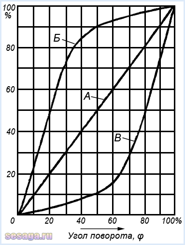
The figure shows different types of dependencies. For linear variable resistors, the dependence is shown in graph A, for nonlinear ones that work:
- according to the logarithmic law - on curve B;
- according to the exponential (inverse logarithmic) law - on graph B.
Also, nonlinear potentiometers can change resistance, as shown in graphs I and E.
All curves are plotted based on the readings of the total and current angle of rotation of the moving part - αn and α from the total Rn and current R resistance. For computer technology and automatic devices, the resistance level can vary in cosine or sine amplitudes.
In order to create wirewound resistors with the required functional characteristics, use a frame of different heights or change the distance in steps between turns of the winding. For the same purposes, in non-wire potentiometers the composition or thickness of the resistive film is changed.
Basic designations
In diagrams of current-carrying circuits, a variable resistor is designated as a rectangle and an arrow, which is directed to the center of the housing. This arrow shows the middle or moving control output.
Sometimes a circuit requires not smooth, but stepped switching. To do this, use a circuit consisting of several fixed resistors. These resistances are turned on depending on the position of the regulator knob. Then the step switching sign is added to the designation, the number on top indicates the number of switch stages.
For gradual volume control, dual potentiometers are integrated into the high-precision equipment. Here, the resistance value of each resistor changes with the movement of one regulator. This mechanism is indicated by a dotted line or double line. If in the diagram the variable resistors are located far from each other, then the connection is simply highlighted with a dotted line on the arrow.
Some dual variants can be controlled independently of each other. In such circuits, the axis of one potentiometer is placed inside another. In this case, the dual connection designation is not used, and the resistor itself is marked according to its positional designation.
The variable resistor can be equipped with a switch that supplies power to the entire circuit. In this case, the switch handle is combined with the switching mechanism. The switch is triggered when the moving contact moves to its extreme position.
Designations of variable resistors
Features of trimming resistors
Such radio components are necessary to configure equipment elements during repair, adjustment or assembly. The main difference between trimming resistors and other models is the existence of an additional locking element. The operation of these resistors uses a linear relationship.
Flat and ring resistive elements are used to create components. If we are talking about using devices under heavy loads, then cylindrical structures are used. In the diagram, instead of an arrow, a tuning adjustment sign is placed.
How to determine the type of variable resistor
The general marking of potentiometers and trimming resistors contains a digital and letter designation of the model, which indicates the type, design feature and rating.
The first resistors had the letter “C” at the beginning of the abbreviation, that is, resistance. The second letter “P” stood for variable or tuning. Next came the group number of the current-carrying part. If we were talking about nonlinear models, then the markings began with the letters CH, ST, SF, depending on the material of manufacture. Then came the registration number.
Today the designation RP is used - variable resistor. Then follows the group: wire - 1 and non-wire - 2. At the end there is also a development registration number separated by a dash.
For ease of designation, miniature resistors use their own color palette. If the radio component is too small, markings are applied in the form of 5, 4 or 3 colored rings. The resistance value comes first, then the multiplier, and finally the tolerance.
Resistor color coding
Important! Radio components are produced by many trading companies around the world. The same designations may refer to different parameters. Therefore, models are selected according to the characteristics included in the description.
The general rule for choosing a resistor is to study the official designations on the manufacturer's website. This is the only way to be sure of the required markings.
Video
elquanta.ru
Variable resistor | Electronics for everyone
It seems like a simple detail, what could be complicated here? But no! There are a couple of tricks to using this thing. Structurally, the variable resistor is constructed in the same way as shown in the diagram - a strip of material with resistance, contacts are soldered to the edges, but there is also a movable third terminal that can take any position on this strip, dividing the resistance into parts. It can serve as both an overclockable voltage divider (potentiometer) and a variable resistor - if you just need to change the resistance.The trick is constructive: Let's say we need to make a variable resistance. We need two outputs, but the device has three. It seems that the obvious thing suggests itself - do not use one extreme conclusion, but use only the middle and second extreme. Bad idea! Why? It’s just that when moving along the strip, the moving contact can jump, tremble and otherwise lose contact with the surface. In this case, the resistance of our variable resistor becomes near infinity, causing interference during setup, sparking and burning out of the graphite track of the resistor, taking the device being tuned out of the permissible setup mode, which can be fatal. Solution? Connect the extreme terminal to the middle one. In this case, the worst thing that awaits the device is a short-term appearance of maximum resistance, but not a break.
Fighting with limit values. If a variable resistor regulates the current, for example, the power supply of an LED, then when brought to the extreme position we can bring the resistance to zero, and this is essentially the absence of a resistor - the LED will char and burn out. So you need to introduce an additional resistor that sets the minimum allowable resistance. Moreover, there are two solutions here - the obvious and the beautiful :) The obvious is understandable in its simplicity, but the beautiful is remarkable in that we do not change the maximum possible resistance, given the impossibility of bringing the engine to zero. When the engine is in the uppermost position, the resistance will be equal to (R1*R2)/(R1+R2) - the minimum resistance. And at the very bottom it will be equal to R1 - the one we calculated, and there is no need to make an adjustment for the additional resistor. It's beautiful! :)
If you need to insert a limitation on both sides, then simply insert a constant resistor at the top and bottom. Simple and effective. At the same time, you can get an increase in accuracy, according to the principle given below.
Increasing accuracy. Sometimes it is necessary to adjust the resistance by many kOhms, but adjust it just a little - by a fraction of a percent. In order not to use a screwdriver to catch these microdegrees of rotation of the engine on a large resistor, they install two variables. One for a large resistance, and the second for a small one, equal to the value of the intended adjustment. As a result, we have two knobs - one “Coarse” and the other “Precisely”. The large one sets the approximate value, and then with the fine one we finish it to perfection.
easyelectronics.ru
How to connect a variable resistor 🚩 variable resistor connection 🚩 Apartment renovation
The term “resistor” comes from the English verb resist, which means “resist”, “obstruct”, “oppose”. Literally translated into Russian, the name of this device means “resistance.” The fact is that a current flows in electrical circuits, which experiences internal opposition. Its value is determined by the properties of the conductor and many other external factors.
This current characteristic is measured in ohms and is related to current and voltage. The resistance of a conductor is 1 ohm if a current of 1 ampere flows through it, and a voltage of 1 volt is applied to the ends of the conductor. Thus, with the help of artificially created resistance introduced into the electrical circuit, it is possible to regulate other important parameters of the system, which can be calculated in advance.
The scope of application of resistors is unusually wide; they are considered one of the most common installation elements. The main function of a resistor is to limit and control current. It is also often used in voltage division circuits when it is necessary to reduce this characteristic of the circuit. Being passive elements of electrical circuits, resistors are characterized not only by the value of the nominal resistance, but also by power, which shows how much energy the resistor is able to dissipate without overheating.
Electronic devices and household electrical circuits use many resistors of different shapes and sizes. These miniature devices differ from each other not only in appearance, but also in rating and performance characteristics. All resistors are conventionally divided into three large groups: constant, variable and tuning.
Most often in devices you can find constant-type resistors that resemble oblong “barrels” with leads at the ends. The resistance parameters in devices of this type do not change significantly from external influences. Small deviations from the nominal value can be caused by internal noise, temperature changes or the influence of voltage surges.
For variable resistors, the user can arbitrarily change the resistance value. To do this, the device is equipped with a special handle that looks like a slider or can rotate. The most common representative of this family of resistors can be seen in the volume controls that are equipped with audio equipment. Turning the handle can smoothly change the parameters of the circuit and, accordingly, increase or decrease the volume. But trimming resistors are intended only for relatively rare adjustments, so they do not have a handle, but a screw with a slot.
www.kakprosto.ru
Variable and tuning resistors. Rheostat.
In one of the previous articles we discussed the main aspects related to working with resistors, so today we will continue this topic. Everything that we discussed earlier concerned, first of all, constant resistors, the resistance of which is a constant value. But this is not the only existing type of resistor, so in this article we will pay attention to elements that have variable resistance.
So, what is the difference between a variable resistor and a constant one? Actually, the answer here follows directly from the name of these elements :) The resistance value of a variable resistor, unlike a constant one, can be changed. How? And that’s exactly what we’ll find out! First, let's look at the conditional circuit of a variable resistor:

It can be immediately noted that here, unlike resistors with a constant resistance, there are three terminals, not two. Now let’s figure out why they are needed and how it all works :)
So, the main part of a variable resistor is a resistive layer that has a certain resistance. Points 1 and 3 in the figure are the ends of the resistive layer. Another important part of the resistor is the slider, which can change its position (it can take any intermediate position between points 1 and 3, for example, it can end up at point 2 as in the diagram). Thus, in the end we get the following. The resistance between the left and central terminals of the resistor will be equal to the resistance of section 1-2 of the resistive layer. Similarly, the resistance between the central and right terminals will be numerically equal to the resistance of section 2-3 of the resistive layer. It turns out that by moving the slider we can get any resistance value from zero to . A is nothing more than the total resistance of the resistive layer.
Structurally, variable resistors are rotary, that is, to change the position of the slider you need to turn a special knob (this design is suitable for the resistor shown in our diagram). Also, the resistive layer can be made in the form of a straight line, accordingly, the slider will move straight. Such devices are called slider or slider variable resistors. Rotary resistors are very common in audio equipment, where they are used to adjust volume/bass, etc. Here's what they look like:

A slider type variable resistor looks a little different:

Often when using rotary resistors, switch resistors are used as volume controls. Surely you have come across such a regulator more than once - for example, on radios. If the resistor is in its extreme position (minimum volume/device is turned off), then if you start to rotate it, you will hear a noticeable click, after which the receiver will turn on. And with further rotation the volume will increase. Similarly, when decreasing the volume - when approaching the extreme position, there will be a click again, after which the device will turn off. A click in this case indicates that the receiver's power has been turned on/off. Such a resistor looks like this:

As you can see, there are two additional pins here. They are precisely connected to the power circuit in such a way that when the slider rotates, the power circuit opens and closes.
There is another large class of resistors that have a variable resistance that can be changed mechanically - these are trimming resistors. Let's spend a little time on them too :)
Trimmer resistors.
Just to begin with, let’s clarify the terminology... In fact, a trimming resistor is variable, because its resistance can be changed, but let’s agree that when discussing trimming resistors, by variable resistors we will mean those that we have already discussed in this article (rotary, slider, etc.) .d). This will simplify the presentation, since we will be contrasting these types of resistors with each other. And, by the way, in the literature, trimming resistors and variables are often understood as different circuit elements, although, strictly speaking, any trimming resistor is also variable due to the fact that its resistance can be changed.
So, the difference between trimming resistors and the variables that we have already discussed, first of all, lies in the number of cycles of moving the slider. If for variables this number can be 50,000 or even 100,000 (that is, the volume knob can be turned almost as much as you like 😉), then for trimming resistors this value is much less. Therefore, trimming resistors are most often used directly on the board, where their resistance changes only once, when setting up the device, and during operation the resistance value does not change. Externally, the tuning resistor looks completely different from the mentioned variables:

The designation of variable resistors is slightly different from the designation of constant ones:

Actually, we have discussed all the main points regarding variables and trimming resistors, but there is one more very important point that cannot be ignored.
Often in the literature or in various articles you can come across the terms potentiometer and rheostat. In some sources this is what variable resistors are called, in others these terms may have some other meaning. In fact, there is only one correct interpretation of the terms potentiometer and rheostat. If all the terms that we have already mentioned in this article related, first of all, to the design of variable resistors, then a potentiometer and a rheostat are different circuits for connecting (!!!) variable resistors. That is, for example, a rotary variable resistor can act both as a potentiometer and as a rheostat - it all depends on the connection circuit. Let's start with the rheostat.

A rheostat (a variable resistor connected in a rheostat circuit) is mainly used to regulate the current. If we connect an ammeter in series with the rheostat, then when we move the slider we will see a changing current value. The resistor in this circuit plays the role of a load, the current through which we are going to regulate with a variable resistor. Let the maximum resistance of the rheostat be equal to , then, according to Ohm’s law, the maximum current through the load will be equal to:
Here we took into account that the current will be maximum at a minimum value of resistance in the circuit, that is, when the slider is in the extreme left position. The minimum current will be equal to:

So it turns out that the rheostat acts as a regulator of the current flowing through the load.
There is one problem with this circuit - if contact is lost between the slider and the resistive layer, the circuit will be open and current will stop flowing through it. You can solve this problem as follows:

The difference from the previous diagram is that points 1 and 2 are additionally connected. What does this give in normal operation? Nothing, no changes :) Since there is non-zero resistance between the resistor slider and point 1, all the current will flow directly to the slider, as in the absence of contact between points 1 and 2. But what happens if contact between the slider and the resistive layer is lost? And this situation is absolutely identical to the absence of a direct connection of the slider to point 2. Then the current will flow through the rheostat (from point 1 to point 3), and its value will be equal to:
That is, if contact is lost in this circuit, there will only be a decrease in the current strength, and not a complete break in the circuit as in the previous case.
We've figured out the rheostat, let's look at a variable resistor connected according to the potentiometer circuit.

Don't miss the article about measuring instruments in electrical circuits - link.
A potentiometer, unlike a rheostat, is used to regulate voltage. It is for this reason that in our diagram you see two voltmeters :) The current flowing through the potentiometer, from point 3 to point 1, remains unchanged when moving the slider, but the resistance value between points 2-3 and 2-1 changes. And since voltage is directly proportional to current and resistance, it will change. When moving the slider down, the resistance of 2-1 will decrease, and accordingly, the readings of voltmeter 2 will also decrease. With this movement of the slider (down), the resistance of section 2-3 will increase, and with it the voltage on voltmeter 1. In this case, the total readings of the voltmeters will be will be equal to the voltage of the power source, that is, 12 V. In the uppermost position on voltmeter 1 there will be 0 V, and on voltmeter 2 - 12 V. In the figure, the slider is located in the middle position, and the readings of the voltmeters, which is absolutely logical, are equal :)
This concludes our consideration of variable resistors; in the next article we will talk about possible connections between resistors, thank you for your attention, I will be glad to see you on our website! 🙂
microtechnics.ru
Electronic variable resistor - Diodnik

In their homemade crafts, radio amateurs almost always use variable resistors to adjust the volume or voltage and, of course, any other parameters. But a device with buttons on the front panel looks much more interesting and modern than with ordinary knobs. The use of microcontroller control is not always advisable in simple crafts, and is also difficult for a beginner, but probably everyone can repeat the electronic variable resistor described below.
The circuit is so small in size that it can be squeezed into almost any homemade device. It fully performs the function of an ordinary variable resistor and does not contain scarce or specific components.
It is based on the field-effect transistor KP 501 (or any other analogue).
By pressing the SB1 button, we accumulate charge on the electrolytic capacitor C 1, which allows us to slightly open the transistor and affect the resistance at the output terminals of the circuit. By pressing the SB2 button, we discharge capacitor C 1, which leads to the gradual closing of the transistor. By constantly pressing any of the buttons, the resistance changes smoothly.
The smoothness of adjustment of such an electronic variable resistor depends on the capacitance of capacitor C 1 and the value of resistor R 1. The maximum resistance that the circuit can simulate depends on the trimming resistor R 2. The circuit starts working immediately and does not require additional settings, except for adjusting the maximum resistance with resistor R 2 .
After turning off the power to the circuit, such an electronic variable resistor does not reset the settings immediately, but the resistance of the circuit increases gradually, which is associated with the self-discharge of capacitor C 1. When using a new and high-quality capacitor C 1, the circuit settings can last about a day.
Probably the most popular application of this circuit will be an electronic volume control. This type of electronic volume control is not without its drawbacks, but the most important factor for hams will likely be ease of repetition.
See a demonstration of how this scheme works below, like it, and also subscribe to our pages on social media. networks!
Note In the video, the electronic analogue of the variable resistor is set to 10 kOhm. The Bside ADM01 multimeter used has automatic range switching and when switching, it does not always immediately determine the current resistance of the circuit.
In contact with
Classmates
Comments powered by HyperComments
Design, designation and types of variable and trimming resistors

If you look at the abundance of radio components that are used in industry and by radio amateurs, it is easy to notice that some radio components can change the value of their main parameter.
Such elements include variable and tuning resistors, the resistance of which can be changed.
Variable resistors are available in a very large range, both for conventional electronic circuits and for circuits using micro-assembly.
All variable and tuning resistors are divided into wire-wound and thin-film.
In the first case, constantan or manganin wire is wound around a ceramic rod. A slide contact moves along the wire winding. Due to this, the resistance between the moving contact and one of the outer terminals of the wire winding changes.
In the second case, a resistive film with a certain resistance is applied to a horseshoe-shaped dielectric plate, and the slider is moved by rotating the axis. Resistive film is a thin layer of carbon (in other words, soot) and varnish. Therefore, in the description for a specific resistor model, in the conductor type paragraph, they usually write “carbon” or “carbon”. Naturally, other materials and substances can be used as the material of the resistive layer.
How do tuning resistors differ from variables?
Trimmer resistors, unlike variables, are designed for a much smaller number of cycles of movement of the moving system (slider). The maximum number for some instances, for example, for a high voltage resistor HP1-9A generally limited to 100.
For variable resistors, the number of cycles can reach 50,000 - 100,000. This parameter is called wear resistance. If this quantity is exceeded, reliable operation is not guaranteed. Therefore, it is strictly not recommended to use trimming resistors instead of variables - this affects the reliability of the device.
Let's take a look at the design of the brand's thin film variable resistor SP1 . In the figure you see a real variable resistor, the resistance of which is 1 MOhm (1,000,000 Ohms).

And here is its internal structure (the protective cover has been removed). The figure also shows the main structural parts.

The fourth pin, visible in the first image, is the metal cap pin that serves as the electrical shield and is usually connected to ground (GND).
The trimmer resistor has a similar design. Take a look. The photo shows a trim resistor SP3-27b (150 kOhm).

The resistance is adjusted using an adjusting screwdriver. For this purpose, a groove is provided in the resistor design.
Now that we have figured out the structure of variable and trimmer resistors, let's find out how they are indicated on the circuit diagram.
Designation of variables and tuning resistors on circuit diagrams.
A typical representation of a variable resistor on a circuit diagram.

As you can see, it consists of the designation of a conventional constant resistor and a “tap” - an arrow. An arrow with a tap symbolizes the middle contact, which we move along the surface of a high-resistance wire wound on a frame or a thin-film coating.
Next to the graphic image there is a letter R with a serial number in the diagram. The nominal resistance is also indicated next to it (for example, 100k - 100 kOhm).
If a variable resistor is included in the circuit as a rheostat (the movable middle terminal is connected to one of the outer ones), then it can be indicated on the diagram with two terminals (in the image it is R2). On foreign circuits, a variable resistor is indicated not by a rectangle, but by a zigzag line. In the picture this is R3.
Variable resistor combined with the power switch.

Used in inexpensive portable equipment. The variable resistor itself is usually used in the sound volume control circuit, and since it is physically (but not electrically!) combined with the switch, when you turn the knob you can turn on the device and immediately adjust the sound volume. Before the widespread introduction of digital volume control, such combined resistors were actively used in portable radios.
In the photo - an adjusting resistor with a switch SP3-3bM .

The photograph clearly shows the design of the switch, which closes its contacts when the dial is turned. Often used in Soviet-made audio equipment (for example, in intercoms, radios, etc.).
Also in electronics, dual or combined variable resistors are used. Their moving contact is structurally combined, and by moving it you can change the resistance of two or more variable resistors at the same time.
Such resistors were often used in analog audio equipment as a stereo balance control or one of the resistors of a multiband equalizer. The number of dual resistors in a high-end equalizer can reach 20.
The first square shows the designation of a dual variable resistor (R1.1; R1.2), which is often used in stereo equipment. The second shows a schematic diagram of a quad variable resistor. Pay attention to the letter marking (R1.1; R1.2; R1.3; R1.4).

In circuit diagrams, combined resistors are indicated using a connecting dotted line. This indicates that their movable contacts are mechanically combined on the shaft of one control knob.
Designation of trimming resistor.

The trimmer resistor in the diagram is designated similarly to a variable resistor with one exception - it does not have an arrow. This tells us that the resistance is adjusted either once when setting up the electronic circuit, or very rarely during maintenance work.
Types of variable and trimming resistors.
In order to have an idea of the whole variety of variables and trimming resistors, let’s take a look at the photographs.
Non-separable variable resistor.
A common variable resistor with wide application. The type is clearly visible: SP4 - 1 , power 0.25 Watt, resistance 100 kOhm.

The resistor at the bottom is filled with epoxy compound, that is, it is non-removable and cannot be repaired. This type is very reliable, as it was produced for defense equipment.
And these are trimming resistors SP3-16b . Resistors SP3-16b are designed for perpendicular installation on a printed circuit board, and their power is 0.125 W. They have a linear (A) functional characteristic. As you can see, their design is very solid and reliable.

Single-turn non-wire trimming resistors.
A small-sized tuning resistor that is soldered directly into the printed circuit board of household equipment. It has very small dimensions and on some boards up to a dozen similar ones are soldered.
The photo below shows trimming resistors SP3-19a (right) power 0.5 W. The material of the resistive layer is metal ceramics.

Lacquer film resistors SP3-38 . Their device is very primitive.

Since its body is open, dust settles on the surface and moisture condenses, which affects the reliability of such a product. The conductor material is cermet, and the power is low - about 0.125 W.
Adjustment of such resistors is carried out with a dielectric screwdriver to avoid short circuits. They are quite easy to find in consumer electronic equipment.
Resistors RP1-302 (pictured right) and RP1-63 (left).

To adjust the resistance of resistors RP1-63, a special screwdriver may be required. If you look closely, the slot for the screwdriver has a hexagonal shape. Unlike SP3-38, such resistors have a protected housing. This has a positive effect on their reliability.
Powerful wirewound trimming resistors.
Shown here is a powerful 3-watt wirewound resistor. SP5-50MA .

Its body is made spacious so that there is air flow to the conductive wire layer for cooling. If you turn the resistor over, you can see its structure in detail, including the insulating strip on which the high-resistance conductor is wound.

High voltage control resistors.
Quite a rare example of a trimmer resistor ( HP1-9A ). Not so long ago they were installed in all CRT TVs and were tied into the high voltage control circuit. Its resistance is 68 MOhm. (I actually pulled it out of the TV to take a photo and show it to you).

HP1-9A itself is a set of cermet resistors. Its working voltage 8500 V(this is 8.5 kilovolts!!!), and the maximum operating voltage is as much as 15 kV! Rated power - 4 W. Why is the adjusting resistor HP1-9A called a set of resistors? Yes, because it consists of several. Its internal structure corresponds to a circuit of 3 separate resistors.
In modern CRT TVs, they are built directly into the TDKS (Diode-cascade line transformer).
In audio equipment with analog control, slide control resistors are often used. They are also called slider . They were widely used in electronic devices to adjust brightness, contrast, volume, tone, etc. Take a look at their design.

The following photo shows a slider variable resistor SP3-23a . From the marking it follows that its power is 0.5 W, and the functional characteristic corresponds to a linear dependence (letter A). Resistance - 1 kOhm.

Just like variable resistors with a circular slider system, slider ones can be double, for example a resistor SP3-23b (bottom one in the first photo). It consists of two variable resistors with a common moving contact.
Trimmer multi-turn resistors.
Very often, especially in special equipment, very convenient and at one time completely scarce multi-turn wire tuning resistors were used.
The leads were also rigid for soldering into ready-made sockets, or made of flexible MGTF wire so that they could be soldered to any point on the board. From zero to maximum resistance, the adjusting screw under the screwdriver had to be turned exactly 40 times. This achieved very high accuracy in setting the circuit parameters.

The photo shows a multi-turn trimmer resistor SP5-2A . The resistance is changed by circular movement of the movable contact system through the worm pair. In 40 full revolutions you can change its resistance from minimum to maximum value. SP5-2A resistors are used in DC and AC circuits, and are designed for a power of 0.5 - 1 W (depending on the modification). Wear resistance - from 100 to 200 cycles. Functional characteristic - linear (A).
More complete information on domestically produced resistors can be obtained from the reference book "Resistors" edited by I.I. Chetvertkova and V.M. Terekhova. It provides data on almost all resistors. You will find the reference book.
Repair of variable resistor.
Since variable resistors are an electromechanical product, they begin to deteriorate over time. Due to wear of the conductive layer and weakening of the pressure of the sliding contact, they begin to work poorly, and a so-called “rustle” appears.
In most cases, there is no point in restoring a faulty variable resistor, but there are exceptions. For example, what you need for replacement may simply not be at hand, or it may be very rare. So, some mixing consoles use quite rare and unique samples. It's difficult to find a replacement for them.
In this case, you can restore the correct operation of the variable resistor using a regular pencil. The lead of a pencil consists of graphite - solid carbon. Therefore, you can carefully disassemble the variable resistor, bend the loose sliding contact, and run a pencil lead over the conductive layer several times. This will restore the conductive layer. It also doesn't hurt to lubricate the coating with silicone grease. Then we put the resistor back together. Naturally, this method is only suitable for thin-film coated resistors.
Honestly, the simplest variable resistor can be made from a simple pencil, because its lead is made of carbon! And finally, let's figure out in our minds how this can be done.
Last time, to connect the LED to a 6.4 V DC source (4 AA batteries), we used a resistor with a resistance of about 200 Ohms. This, in principle, ensured normal operation of the LED and prevented it from burning out. But what if we want to adjust the brightness of the LED?
To do this, the simplest option is to use a potentiometer (or trimming resistor). In most cases, it consists of a cylinder with a resistance adjustment knob and three contacts. Let's figure out how it works.
It should be remembered that it is correct to adjust the brightness of the LED by PWM modulation, and not by changing the voltage, since for each diode there is an optimal operating voltage. But to clearly demonstrate the use of a potentiometer, such use of it (the potentiometer) for educational purposes is acceptable.
By releasing the four clamps and removing the bottom cover, we will see that the two outer contacts are connected to the graphite track. The middle contact is connected to the ring contact inside. And the adjustment knob simply moves the jumper connecting the graphite track and the ring contact. When you rotate the knob, the arc length of the graphite track changes, which ultimately determines the resistance of the resistor.
 It should be noted that when measuring the resistance between the two extreme contacts, the multimeter reading will correspond to the nominal resistance of the potentiometer, since in this case the measured resistance corresponds to the resistance of the entire graphite track (in our case 2 kOhm). And the sum of resistances R1 and R2 will always be approximately equal to the nominal value, regardless of the angle of rotation of the adjustment knob.
So, by connecting a potentiometer in series to the LED, as shown in the diagram, changing its resistance, you can change the brightness of the LED. Essentially, when we change the resistance of the potentiometer, we change the current passing through the LED, which leads to a change in its brightness.

 However, it should be remembered that for each LED there is a maximum permissible current, if exceeded, it simply burns out. Therefore, to prevent the diode from burning out when the potentiometer knob is turned too far, you can connect another resistor in series with a resistance of about 200 Ohms (this resistance depends on the type of LED used) as shown in the diagram below.

For reference: LEDs need to be connected with the long “leg” to +, and the short one to -. Otherwise, the LED simply will not light up at low voltages (it will not pass current), and at a certain voltage, called the breakdown voltage (in our case it is 5 V), the diode will fail.

Let's check the validity of the formulas shown here using a simple experiment.
Let's take two resistors MLT-2 on 3 And 47 Ohm and connect them in series. Then we measure the total resistance of the resulting circuit with a digital multimeter. As we can see, it is equal to the sum of the resistances of the resistors included in this chain.

Measuring total resistance in series connection
Now let's connect our resistors in parallel and measure their total resistance.

Resistance measurement in parallel connection
As you can see, the resulting resistance (2.9 Ohms) is less than the smallest (3 Ohms) included in the chain. This leads to another well-known rule that can be applied in practice:
When resistors are connected in parallel, the total resistance of the circuit will be less than the smallest resistance included in this circuit.
What else needs to be considered when connecting resistors?
Firstly, Necessarily their rated power is taken into account. For example, we need to select a replacement resistor for 100 Ohm and power 1 W. Let's take two resistors of 50 ohms each and connect them in series. How much power dissipation should these two resistors be rated for?
Since the same direct current flows through series-connected resistors (for example 0.1 A), and the resistance of each of them is equal 50 ohm, then the dissipation power of each of them must be at least 0.5 W. As a result, on each of them there will be 0.5 W power. In total this will be the same 1 W.
This example is quite crude. Therefore, if in doubt, you should take resistors with a power reserve.
Read more about resistor power dissipation.
Secondly, when connecting, you should use resistors of the same type, for example, the MLT series. Of course, there is nothing wrong with taking different ones. This is just a recommendation.
(fixed resistors), and in this part of the article we’ll talk about, or variable resistors.
Variable resistance resistors, or variable resistors are radio components whose resistance can be change from zero to nominal value. They are used as gain controls, volume and tone controls in sound-reproducing radio equipment, are used for precise and smooth adjustment of various voltages and are divided into potentiometers And tuning resistors.
Potentiometers are used as smooth gain controls, volume and tone controls, serve for smooth adjustment of various voltages, and are also used in tracking systems, in computing and measuring devices, etc.

Potentiometer called an adjustable resistor having two permanent terminals and one movable. The permanent terminals are located at the edges of the resistor and are connected to the beginning and end of the resistive element, forming the total resistance of the potentiometer. The middle terminal is connected to a movable contact, which moves along the surface of the resistive element and allows you to change the resistance value between the middle and any extreme terminal.
The potentiometer is a cylindrical or rectangular body, inside of which there is a resistive element made in the form of an open ring, and a protruding metal axis, which is the handle of the potentiometer. At the end of the axis there is a current collector plate (contact brush) that has reliable contact with the resistive element. Reliable contact of the brush with the surface of the resistive layer is ensured by the pressure of a slider made of spring materials, for example, bronze or steel.


When the knob is rotated, the slider moves along the surface of the resistive element, as a result of which the resistance changes between the middle and extreme terminals. And if voltage is applied to the extreme terminals, then an output voltage is obtained between them and the middle terminal.
The potentiometer can be schematically represented as shown in the figure below: the outer terminals are designated by numbers 1 and 3, the middle one is designated by number 2.

Depending on the resistive element, potentiometers are divided into non-wire And wire.
1.1 Non-wire.
In non-wire potentiometers, the resistive element is made in the form horseshoe-shaped or rectangular plates made of insulating material, on the surface of which a resistive layer is applied, which has a certain ohmic resistance.
Resistors with horseshoe-shaped resistive element has a round shape and rotational movement of the slider with a rotation angle of 230 - 270°, and resistors with rectangular the resistive element has a rectangular shape and the translational movement of the slider. The most popular resistors are the types SP, OSB, SPE and SP3. The figure below shows a SP3-4 type potentiometer with a horseshoe-shaped resistive element.


The domestic industry produced potentiometers of the SPO type, in which the resistive element is pressed into an arcuate groove. The body of such a resistor is made of ceramic, and to protect against dust, moisture and mechanical damage, as well as for electrical shielding purposes, the entire resistor is covered with a metal cap.
Potentiometers of the SPO type have high wear resistance, are insensitive to overloads and are small in size, but they have a drawback - the difficulty of obtaining nonlinear functional characteristics. These resistors can still be found in old domestic radio equipment.

1.2. Wire.
IN wire In potentiometers, the resistance is created by a high-resistance wire wound in one layer on a ring-shaped frame, along the edge of which a moving contact moves. To obtain reliable contact between the brush and the winding, the contact track is cleaned, polished, or ground to a depth of 0.25d.


The structure and material of the frame is determined based on the accuracy class and the law of change in resistance of the resistor (the law of change in resistance will be discussed below). The frames are made of a plate, which, after winding the wires, is rolled into a ring, or a finished ring is taken, on which the winding is laid.
For resistors with an accuracy not exceeding 10 - 15%, the frames are made of a plate, which, after winding the wires, is rolled into a ring. The material for the frame is insulating materials such as getinax, textolite, fiberglass, or metal - aluminum, brass, etc. Such frames are easy to manufacture, but do not provide precise geometric dimensions.
Frames from the finished ring are manufactured with high precision and are mainly used for the manufacture of potentiometers. The material for them is plastic, ceramics or metal, but the disadvantage of such frames is the difficulty of winding, since special equipment is required to wind it.
The winding is made of wires made of alloys with high electrical resistivity, for example, constantan, nichrome or manganin in enamel insulation. For potentiometers, wires made of special alloys based on noble metals are used, which have reduced oxidation and high wear resistance. The diameter of the wire is determined based on the permissible current density.
2. Basic parameters of variable resistors.
The main parameters of resistors are: total (nominal) resistance, form of functional characteristics, minimum resistance, rated power, rotational noise level, wear resistance, parameters characterizing the behavior of the resistor under climatic influences, as well as dimensions, cost, etc. However, when choosing resistors, attention is most often paid to the nominal resistance and less often to the functional characteristics.
2.1. Nominal resistance.
Nominal resistance resistor is indicated on its body. According to GOST 10318-74, the preferred numbers are 1,0 ; 2,2 ; 3,3 ; 4,7 Ohm, kiloohm or megaohm.
For foreign resistors, the preferred numbers are 1,0 ; 2,0 ; 3,0 ; 5.0 Ohm, kiloohm and megaohm.
Permissible deviations of resistances from the nominal value are set within ±30%.
The total resistance of the resistor is the resistance between the outer terminals 1 and 3.

2.2. Form of functional characteristics.
Potentiometers of the same type may differ in their functional characteristics, which determine by what law the resistance of the resistor changes between the extreme and middle terminals when the resistor knob is turned. According to the form of functional characteristics, potentiometers are divided into linear And nonlinear: for linear ones, the resistance value changes in proportion to the movement of the current collector, for nonlinear ones it changes according to a certain law.
There are three basic laws: A— Linear, B– Logarithmic, IN— Reverse Logarithmic (Exponential). So, for example, to regulate the volume in sound-reproducing equipment, it is necessary that the resistance between the middle and extreme terminals of the resistive element varies according to inverse logarithmic law (B). Only in this case is our ear able to perceive a uniform increase or decrease in volume.
Or in measuring instruments, for example, audio frequency generators, where variable resistors are used as frequency-setting elements, it is also required that their resistance varies according to logarithmic(B) or inverse logarithmic law. And if this condition is not met, then the generator scale will be uneven, which will make it difficult to accurately set the frequency.
Resistors with linear characteristic (A) are used mainly in voltage dividers as adjustment or trimmers.
The dependence of the change in resistance on the angle of rotation of the resistor handle for each law is shown in the graph below.
To obtain the desired functional characteristics, major changes are not made to the design of potentiometers. For example, in wirewound resistors, the wires are wound with varying pitches or the frame itself is made of varying width. In non-wire potentiometers, the thickness or composition of the resistive layer is changed.

Unfortunately, adjustable resistors have relatively low reliability and limited service life. Often, owners of audio equipment that has been in use for a long time hear rustling and crackling sounds from the speaker when turning the volume control. The reason for this unpleasant moment is a violation of the contact of the brush with the conductive layer of the resistive element or wear of the latter. The sliding contact is the most unreliable and vulnerable point of a variable resistor and is one of the main reasons for part failure.
3. Designation of variable resistors on diagrams.
On circuit diagrams, variable resistors are designated in the same way as constant ones, only an arrow directed to the middle of the case is added to the main symbol. The arrow indicates regulation and at the same time indicates that this is the middle output.

Sometimes situations arise when requirements for reliability and service life are imposed on a variable resistor. In this case, smooth control is replaced by step control, and a variable resistor is built on the basis of a switch with several positions. Constant resistance resistors are connected to the switch contacts, which will be included in the circuit when the switch knob is turned. And in order not to clutter the diagram with the image of a switch with a set of resistors, only the symbol of a variable resistor with a sign is indicated step regulation. And if there is a need, then the number of steps is additionally indicated.

To control volume and timbre, recording level in stereo sound-reproducing equipment, to control frequency in signal generators, etc. apply dual potentiometers, the resistance of which changes simultaneously when turning general axis (engine). In the diagrams, the symbols of the resistors included in them are placed as close to each other as possible, and the mechanical connection that ensures the simultaneous movement of the sliders is shown either with two solid lines or with one dotted line.

The belonging of resistors to one double block is indicated according to their positional designation in the electrical diagram, where R1.1 is the first resistor of the dual variable resistor R1 in the circuit, and R1.2- second. If the resistor symbols are at a great distance from each other, then the mechanical connection is indicated by segments of a dotted line.

The industry produces dual variable resistors, in which each resistor can be controlled separately, because the axis of one passes inside the tubular axis of the other. For such resistors, there is no mechanical connection that ensures simultaneous movement, therefore it is not shown on the diagrams, and membership of a dual resistor is indicated according to the positional designation in the electrical diagram.
Portable household audio equipment, such as receivers, players, etc., often use variable resistors with a built-in switch, the contacts of which are used to supply power to the device circuit. For such resistors, the switching mechanism is combined with the axis (handle) of the variable resistor and, when the handle reaches the extreme position, it affects the contacts.

As a rule, in the diagrams, the contacts of the switch are located near the power source in the break of the supply wire, and the connection between the switch and the resistor is indicated by a dotted line and a dot, which is located at one of the sides of the rectangle. This means that the contacts close when moving from a point, and open when moving towards it.
4. Trimmer resistors.
Trimmer resistors are a type of variables and are used for one-time and precise adjustment of electronic equipment during its installation, adjustment or repair. As trimmers, both variable resistors of the usual type with a linear functional characteristic, the axis of which is made “under a slot” and equipped with a locking device, and resistors of a special design with increased accuracy of setting the resistance value, are used.

For the most part, specially designed tuning resistors are made in a rectangular shape with flat or circular resistive element. Resistors with a flat resistive element ( A) have a translational movement of the contact brush, carried out by a micrometric screw. For resistors with a ring resistive element ( b) the contact brush is moved by a worm gear.

For heavy loads, open cylindrical resistor designs are used, for example, PEVR.

In circuit diagrams, tuning resistors are designated in the same way as variables, only instead of the control sign, the tuning control sign is used.

5. Inclusion of variable resistors in an electrical circuit.
In electrical circuits, variable resistors can be used as rheostat(adjustable resistor) or as potentiometer(voltage divider). If it is necessary to regulate the current in an electrical circuit, then the resistor is turned on with a rheostat; if there is voltage, then it is turned on with a potentiometer.
When the resistor is turned on rheostat the middle and one extreme output are used. However, such inclusion is not always preferable, since during the regulation process, the middle terminal may accidentally lose contact with the resistive element, which will lead to an unwanted break in the electrical circuit and, as a consequence, possible failure of the part or the electronic device as a whole.

To prevent accidental breakage of the circuit, the free terminal of the resistive element is connected to a moving contact, so that if the contact is broken, the electrical circuit always remains closed.

In practice, turning on a rheostat is used when they want to use a variable resistor as an additional or current-limiting resistance.
When the resistor is turned on potentiometer All three pins are used, which allows it to be used as a voltage divider. Let's take, for example, a variable resistor R1 with such a nominal resistance that it will extinguish almost all of the power source voltage coming to the HL1 lamp. When the resistor knob is twisted to the highest position in the diagram, the resistance of the resistor between the upper and middle terminals is minimal and the entire voltage of the power source is supplied to the lamp, and it glows at full heat.

As you move the resistor knob down, the resistance between the upper and middle terminals will increase, and the voltage on the lamp will gradually decrease, causing it to not glow at full intensity. And when the resistor reaches its maximum value, the voltage on the lamp will drop to almost zero and it will go out. It is by this principle that volume control in sound-reproducing equipment occurs.
The same voltage divider circuit can be depicted a little differently, where the variable resistor is replaced by two constant resistors R1 and R2.

Well, that’s basically all I wanted to say about variable resistance resistors. In the final part, we will consider a special type of resistors, the resistance of which changes under the influence of external electrical and non-electrical factors -.
Good luck!
Literature:
V. A. Volgov - “Parts and components of radio-electronic equipment”, 1977
V. V. Frolov - “The language of radio circuits”, 1988
M. A. Zgut - “Symbols and radio circuits”, 1964


