Replacing the sound processor in a Chinese radio. Sound amplifier chips for car radios. Review. The best radios with a DVD drive
I, too, like many here, became the owner of this car, everything suits me, but the sound is somehow not the same, as if it is working under load, there are no normal highs, and there are really no lows either. There is a predominance of mid frequencies, which is not the case for audio equipment that should brighten up the road. This sound usually either gives you a headache or makes you even more tired from the road. Therefore, they are probably not so popular, and probably everyone is trying to change them. Although many try to fix this problem by replacing the acoustics, from my experience this is more likely a consequence of the problem and not the problem itself!
So, instead of installing acoustics and trying to do something tricky with replacing the mayfun, there is an elementary way out! True, it is a little expensive for some, but not for others.
And so, what is required is to replace the rear speakers with more powerful ones of your taste and 4 ohms, it is better to check with a tester, a little more than 4 ohms is allowed, less is not
Second and most important. This is a replacement for the standard amplifier of the car radio that is located inside it, I am currently selecting an amplifier microcircuit based on data shields.
The car radio has a Chinese amplifier installed LA47201-such a microcircuit is found in the JVC KD-G425 and in many other similar mayfuns, the price of such a microcircuit in stores is about LA47201 - 245.60 rubles.
I worked for more than a year and a half in a car radio repair service center. In JVC I installed mikruhi from the Pioneer and in the Pioneer from JVC, now I will select an analogue and post information on the replacement.
Well, as expected, the microcircuit is extremely weak, hence the attitude towards the speakers, as the manufacturer writes, the recommended 8 ohms, but can also work with 4 ohms
You can supply any available from: TDA7381-7386, TDA7560, TA8263-8268, TA8271-8277, TB2901-2906, LA47501-LA47515, LA4743, etc. The only thing is, pay attention to the 1, 10, 16, 25 legs, well, their power is different - this was taken from the forum, it’s a long time to write (I meant that the microcircuits could be fake and their pinouts could also be different)! the price of such microcircuits is up to 500 rubles
I'll just add that I changed this microcircuit to Pal007, the price of such a microcircuit in Novosibirsk is from 900 to 2000 t r costs in all pioneers, the difference is in the most expensive ones radio models, only in a linear amplifier of higher quality!
At the moment I’m charging the batteries for the camera, I’ll post pictures later for those who understand, a warning to others that all the work done to replace the amplifier chip can, if it’s soldered and soldered incorrectly, damage the printed circuit board and lead to a short circuit. (again, I recommend turning to people who know how to solder such microcircuits so that there are no problems in the future))
Well, that's it, I redid it and oh the miracle of such a sound, I'm on a SONY pile m9900 I haven't heard. The sound became more powerful, the lows began to pump even with standard speakers!!! The quality has increased 100 times, and not by 5 - 10 percent, the only thing is that you shouldn’t listen to everything with such a chip, it’s bad for the speakers. And so, people, you can’t even imagine how it started to sound! And if you install new acoustics instead of the standard ones, you will definitely be pleasantly surprised, and at the same time, everything remains under warranty, the radio is standard :) The main thing is to do everything efficiently, and remove traces of soldering with alcohol. 🙂
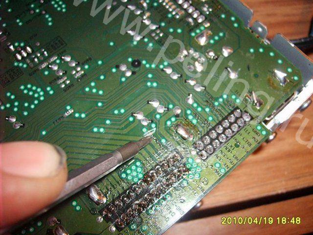
Here, as promised, photos of my modifications for today with my mafon, I was very pleased!
And I wanted to say about the 25th leg, where I use a screwdriver to show the road that I cut off above, this was done so that there would be no interference when turning off the ignition, interference from my alarm system....!
To remove a standing microcircuit more carefully, you can use a suction device, or carefully break it out, or cut it out with a scalpel, I soldered it out just in case, it will be useful for experiments or as a spare tire.
It is better to install the PAL007C microcircuit; it pumps up the lows well, the only thing that is missing is the highs, but this can be solved simply by installing tweeters. Now, at maximum sound power, namely 33 with bass at zero, the speakers have no distortion or power loss!
It also works well at higher bass levels, but there are already not enough speakers here.
Let me make a reservation once again: when choosing acoustics, you can come with a digital tester and measure the resistance of the acoustics you want to take. It should not be lower than 4 ohms! This is a move by companies, real acoustics are a little more than 4 ohms, which means that the number of turns is greater than in those where the resistance is lower, which means the range of reproduced frequencies is also narrowed. So standard 8 Ohm speakers have a higher range of reproduced frequencies. But only at Medium and Low frequencies, HF is very lacking, but the quality with such an alteration simply cannot be compared with what it was, that’s all!
If you have any questions about the alteration, ask, I will help in any way I can!


((div))((span class="apple-style-span" style="background-color: rgb(255, 255, 255); font-size: 12px;"))((font class="apple- style-span" color="#cc0000" face="times new roman"))((/font))((/span))((/div))((span class="apple-style-span" style ="color: rgb(204, 0, 0); font-family: times new roman; font-size: 12px; background-color: rgb(255, 255, 255); ")) Recently, the Russian market has been rapidly filling up radio equipment made in China. Buyers are mainly attracted by its quite decent appearance and low cost. And it works, as many people think at the time of purchase, quite well. However, a little time passes and the joy of acquiring a new thing gives way to disappointment. Many stereophonic car radios made in China turn out to be monophonic, although their cases have the inscription “stereo” on them, and the radios are equipped with two output connectors and two-channel magnetic heads. What to do? The author of the article published below offers readers a fairly simple way to solve this problem. ((p)) It would seem that it is not difficult to convert a mono radio into a stereo one. You just need to add another single-channel playback amplifier. But the Chinese radios I encountered had only two controls: a volume control and a radio station tuning knob. Moreover, the variable resistor of the volume control was single. Replacing it with a domestic dual one would require a very large design modification. Therefore, I took a simpler path: I built a new two-channel playback amplifier, which I bring to the attention of readers. ((/p))((p))The amplifier consists of two identical channels, so it is enough to describe one of them. Its circuit diagram is shown in ((b))Fig. 1((/b)). The signal from head B1 installed in the radio tape recorder is supplied to the pre-amplifier, made on the dA1.1 microcircuit, through the isolation capacitor SZ. Correction of the frequency response in the region of higher frequencies is provided by capacitor C1, which, together with the inductance of the head winding B1, forms a parallel oscillatory circuit tuned to a frequency of 18...20 kHz. ((/p))((p)) The standard frequency response is formed by the frequency-dependent OOS circuit r3, r4, C4. The correction time constant is chosen to be 120 μs and is determined by the values of resistor r3 and capacitor C4. Resistor r4 limits the rise in frequency response in the region of lower audio frequencies. ((/p))((p)) The AF signal from the radio receiver of the radio is supplied to the input of the dA1 microcircuit. 1 through resistor r2. The dA2 chip performs the functions of an electronic volume control. A simplified version of its typical inclusion is used. Volume regulates the voltage supplied to pin 13 dA2 from variable resistor r10, and stereo balance regulates the voltage supplied to pin 12 of this microcircuit from divider r7, r8. Since there is no stereo balance function in the radio, pin 12 is set to a voltage equal to half the supply voltage, which corresponds to the middle position of the stereo balance control slider. ((/p))((p))The power amplifier is assembled on a dA3 chip. It is included according to the standard scheme; only the values of some elements have been changed. The voltage to this microcircuit comes from pin 9 of the dA2 microcircuit through capacitor C7. The output voltage is removed from pin 4 daЗ and is supplied through capacitor C9 to the head of loudspeaker BA1. There is no cassette in the tape recorder, the receiver is working. When installing the cassette, the CVL motor starts running, and the receiver turns off. The playback amplifier is constantly energized, and one or another source of the audio signal is connected to it as needed. ((/p))((p)) It is worth noting that there are Chinese-made car radios with monophonic and stereophonic radio receiving paths. In the first case, sound signals from their outputs are supplied simultaneously to both channels of the playback amplifier, and in the second, the signals of the left and right channels are supplied separately to the channels of the corresponding amplifier.((/p))((p))The amplifier is mounted on a single-sided printed circuit board foil getinax (((b))Fig. 2((/b))). During installation, fixed resistors MLT-0.125 were used; variable - the volume control available in the radio (usually its resistance is 22 kOhm); oxide capacitors K50-6, K50-16, K53-1a, the rest - K10-7V; loudspeaker heads are automotive grade with a nominal electrical resistance of 4 ohms. Microcircuits dАЗ, dАЗ must be fixed on heat sinks.((/p))((p))((table cellspacing="2" cellpadding="2" align="center"))((tbody))((tr)) ((td))
 ((/td))((/tr))((tr))((td align="center"))((font class="n5" style="font-size: 12px; "))((b ))Fig.2
 Printed circuit board((/b))((/font))((/td))((/tr))((/tbody))((/table))((/p))((p))When With known good parts, the amplifier starts working immediately. Its setup consists of selecting the values of resistors r7, r8 so that the stereo balance determined by them is at zero level. Usually this can be achieved when the values of these resistors fluctuate within 2 kOhm.((/p))((p))The mounted and configured board should be secured inside the cassette player, which does not cause any difficulties.((/p))((p ))The described method of modifying radios is very reliable and is available to many owners of Chinese-made car radios who are not satisfied with their work.((/p))((/span))((span class="apple-style-span" style="font -family: tahoma, arial; background-color: rgb(255, 255, 255); "))((span style="color: rgb(0, 0, 205); text-decoration: underline; font-size: 14pt; "))Files for the article PLAYBACK AMPLIFIER FOR CHINESE CAR RADIO((/span))((/span))((span class="apple-style-span" style="color: rgb(204, 0, 0) ; font-family: times new novel; font-size: 12px; background-color: rgb(255, 255, 255); "))((p))((i))((b))Editors' note.( (/b))
In the HF version proposed by the author, the time constant circuit of 120 μs does not turn off during radio reception. And although this “evil” is less than the original Chinese version, it will still lead to some attenuation when reproducing higher sound frequencies, which will be noticeable when receiving VHF radio stations. This influence can be eliminated by including a constant resistor instead of elements r4, C4 and selecting it until an acceptable level of volume and nonlinear distortion is obtained. The switch can be conveniently combined with the switch of the compact cassette player.((/i))((/p))((/span)) Section:
Car radio power amplifier chip
The car radio power amplifier chip was developed in 1998 by the world famous company Philips. The car radio power amplifier chip was intended to amplify the head unit.
Brief performance characteristics of the microcircuit
The data is given below:
- equipped with a built-in supply voltage converter;
- the voltage converter at a relatively low voltage allows you to create an output power of 70 W at a load of 4 ohms;
- the chip has a class B output power of about 18 W at a voltage of 14.4 V;
- The power supply of the internal circuit can be increased by increasing the switching on of the converter, which increases the output voltage.
Note. It is necessary to objectively understand that the voltage booster does not always function, but only when the output power crosses a certain limit. And this mode of operation was called N.
The microcircuit also contains a MODE output, which is capable of operating in three modes, namely:
- active mode ON;
- standby mode STD-BY;
- in silent MUTE state.
In its functional assets, the microcircuit also contains specialized integrated units for protection against:
- possible short circuit of conductors located at the output;
- short circuit caused by the intersection of a power wire with a positive charge and a common wire;
- temperature overheating in case of operating overload.
The TDA chip contains a dynamic distortion detection detector, which turns on automatically if distortion doses occur in the output signal.
This does not occur with the saturation effect:
- The input signal voltage increases, however, the output signal does not increase, continuing to be within the voltage limits created by the power amplifier.
This microcircuit is represented by film capacitors, namely:
- C3 – 0.1 µF;
- C4 – 2.2 µF;
- C7 and C8 – 3300 µF.
There are also X2 terminals, which are necessary to both turn the amplifier on and off.
Note. The MODE output can be artificially connected to the REMOTE output on the car radio, which in turn will create the possibility of remote control. In this case, immediately after starting the car radio, an output signal with a voltage of 12 will appear, which will actually drive the amplifier.
The TDA1562Q microcircuit also has additional X3 terminals, which can, if necessary, be used as an indicator of the emergency state of the amplifier. For this purpose, it is enough to simply connect an LED to the X3 terminals.
Distinctive features of the TDA chip for a car radio amplifier
Here they are:
- Since the flange of the amplifier chip is connected directly to the common wire, there is no need for an insulating radiator gasket if the attachment point is a radiator.
Note. It is imperative to lubricate the fastenings with a specialized heat-conducting paste, otherwise this design will last a short period of time.
- Additionally, it will be mandatory to tin all power paths.
Moments that motorists pay little attention to
As a rule, they are like this:
- You must always remember that over time, the internal wiring of the car radio (see) and its additional components deteriorate, which can cause interruptions in the operation of the amplifier;
- it is extremely important to effectively correlate the voltage created at the input with the one that should be obtained at the output;
- It is imperative that you carefully read the detailed illustrated diagram, which can easily be found on the Internet;
- An equally important point is the proper operation of the radiator, which must not only function, but function effectively; otherwise, the amplifier of the microcircuit will overheat and it will simply go out of its working state.
Distinctive advantages and disadvantages of choosing a TDA chip from Philips
| low market value | slight technological obsolescence |
| speed and ease of operation | lack of modern functionality |
| proper reliability and performance and the required degree of functionality | Difficulty combining with luxury car radios |
| wide range of compatibility with car radios | the need for annual inspection of all components |
| Availability of operating instructions on the Internet | |
| simplicity of structure | |
| possibility of continuous operation in uninterrupted mode |
If we talk about objective realities today, it should be noted that the TDA1562Q chip for a car radio amplifier (see) is best used for nationally produced cars, since in this case, there are no compatibility problems a priori, which cannot be said about modern foreign cars.
Note. Sometimes a microcircuit is delivered with a manufacturing defect, so before purchasing it directly, you need to carefully inspect everything visually.
As a rule, you need to pay attention to:
- absence of any obvious physical defects;
- the presence of all components that are indicated in the attached operational diagram;
- make sure that replacement is possible, if necessary, and that the seller has a warranty for the product.
Video review and photo materials will help you get more detailed information. Testing the amplifier can be done with your own hands, since instructions can be found almost everywhere today. The price of the TDA amplifier is not very high.
Budget cars are budgetary because manufacturers cut total savings on everything. In them they also additionally eliminate high frequencies in standard radios. However, even in middle-class cars, audio systems from well-known manufacturers, including those from Japan, have the same disadvantages.
They are different in different cars, but can be eliminated by the owners themselves.
The standard radio in Lada Priora and Lada Vesta cars has good sound and a fairly wide range of functionality. For the most part, car owners are happy with it. However, a number of simple improvements can improve the sound and noise filtering.
Modification of the standard radio consists of replacing the microcircuit in the amplifier (you must install the “ULF TDA7560”) and the amplifier power capacitor. Instead of a standard capacitor, install two: 10,000 µF and a film capacitor “K 73-17” 0.47 µF 250V, which creates a power reserve. The sound then rises to a higher volume level with clearer reproduction.
Attention: on the radio components market, the TDA7560 microcircuit has interchangeable analogues: TDA7851; PAL007; TDA7850.
"Mazda 3"
In radios installed by the manufacturer in Mazda 3 cars, the amount of distortion increases with increasing sound strength - constant wheezing at a power level of more than 20 divisions.

The problem is not in the speakers, but in the power amplifier, distorting the sound signal. The output is to increase the voltage to 16-18V. However, it is not in the car. You can achieve your goal, increase the voltage from 12V to 18V, using the universal converter URZ1122.
This power supply is manufactured by different companies under different names and different markings. Therefore, the specific choice of the DC-DS converter model is up to the car owner. The only thing to keep in mind is that different models have different sizes. Compact converters are easily built into the radio, larger ones are installed on the outside of the case.
Hyundai Solaris
In Hyundai Solaris, many owners are not satisfied with the sound of the radio. They solve this problem in two ways:
- install additional amplifiers, subwoofers, and pull wires with a large cross-section throughout the cabin;
- The radio itself is being modified.

Both methods achieve the same result. But in the first case, it is expensive and the car interior becomes cluttered. The second method costs little money and does not spoil the internal design. All you need is time and desire. The process is standard. Replace the chip in the standard TOSHIBA TB 2926 AHQ amplifier with a TDA 7560 and increase the capacitor power to at least 3900-4000 uF. The ideal option is a 10,000 µF capacitor.
The process of replacing radio components itself is not complicated. Difficulties arise when removing the radio from the locks holding it and disassembling it. Patience and attentiveness will help here. Ultimately, the work will pay off with spacious, clear sound on standard speakers.
"Kia Rio"
In the Kia Rio, the manufacturer installs a standard MOBIS PA710 QBR radio made in China. It has the same problems as the Hyundai Solaris, although the radios are from different manufacturers.

They have one thing in common - the standard TOSHIBA TB 2926 AHQ amplifier. Therefore, the solution to the problem is the same as that of Solaris. In addition, the audio system does not have a USB connector. This drawback is also easily eliminated.
"Kia Sorento"
Car enthusiasts connect a rear view camera to the standard Kia X7BB radio on a Kia Sorento. To obtain Hi-Fi sound, change it to the X8BB model.

A number of radios from well-known manufacturers with high sound quality, installed on various brands of cars, also require improvement.
Many models of both cars and trucks are equipped with Japanese Pioneer radios. This is one of the best options for a car radio, with good sound and a wide range of functions. However, it has a significant problem. It does not turn off, but goes into sleep mode with backlit keys and a working clock. This distracts the driver while driving and drains the battery when parked.

The problem is resolved by reconfiguring the audio system.
- By pressing number 2 we enter the menu.
- Find the System section;
- Activate PW Save;
- Turn off the radio with the OFF button, after which it will go into sleep mode again;
- We remove the problem with button 1. Only the clock remains. If you want to remove them too, click on number 4.
Problem solved. There will be no return to sleep mode.
Chinese radios with tuner QSD-RT-L93
Modification of a Chinese radio with the QSD-RT-L93 tuner is very difficult and only professionals can do it. But even a novice car enthusiast can improve the quality of radio signal reception.
The radio manufacturer ignored the operation of the display controller. As a result, interference is emitted outward through the radio panel and reaches the antenna input. This is most clearly manifested when installing the antenna inside the cabin, on the glass. The solution is to shield the audio system housing, which will lock the interference inside it. This can be achieved by simply grounding the aluminum base of the display.

Additionally, you can strengthen the LED power converter by adding a 1 µF ceramic capacitor to the circuit.
Using simple and affordable methods, you can significantly improve the sound of standard audio systems and eliminate some design flaws.


