STM32F407(STM32F4-DISCOVERY) - Non-standard approach - Standard library part 1. Peripheral Standard Library
Once again I want to write about a simple start with STM32, only this time without using anyone’s templates or examples - with an explanation of each step. The articles will have continuous numbering of steps.
1. Install IAR
Building a project in IAR
1. Preprocessor
- deletes comments
2. Compiler
3. Linker
3. Create a new project in IAR
After launching IAR, a window appears information center, which we don't need. Click the Project menu -> Create New Project. Select toolchain: ARM (it’s unlikely you will have anything else on that list), Project templates: C –> main.

In the left window (“Workspace”) right click mouse call up the menu and create new group(Add –>
Right click on CMSIS
To the group Startup
We're done with CMSIS.
To the group StdPeriphLib
To the group User
5. Setting up the project
- General options –> Target –>
 Select ST –> STM32F100 –> ST STM32F100xB. This is our controller. 2. General options –> Library Configuration –> CMSIS: check the Use CMSIS checkbox. So we will use the CMSIS library built into the compiler. Since version 6.30, IAR began to ship with a built-in CMSIS, and this seems to be better - but it introduced some confusion with older projects. 3. C/C++ compiler –>
  * Debugger –> Setup –> Driver: select ST–Link, since this is the programmer built into the Discovery board. Now we configure the programmer itself: * Debugger –> ST–LINK –> Interface: select SWD (the programmer on the board is connected to the controller via SWD, not via JTAG). * Debugger –>
#include "stm32f10x_conf.h" void main()

{
while(1)

{

}

}
<1000000; i++);

for(i=0; i<1000000; i++);
#include "stm32f10x_conf.h"void main()
{
int i;
while(1)
{
for(i=0; i<1000000; i++);
<1000000; i++); } }
 archive with the GPIO project. Luckily, you can save this project and use it as a template so you don't have to go through all the setup again. The whole cycle: 1. I/O ports (/index.php/stm32-from_zero_to_rtos-2_timers/ "STM32 - from zero to RTOS. 2: Timer and interrupts") (/index.php/stm32-from_zero_to_rtos-3_timer_outputs/ "STM32 - from scratch to RTOS. 3: Timer outputs") [Once again I want to write about a simple start with STM32, only this time without using anyone’s templates or examples - with an explanation of each step. The articles will have continuous numbering of steps.
0. We extract the STM32VLDiscovery board
We buy it in the store, it costs 600 rubles. You will need to install drivers on the board - I think this will not cause any difficulties.
1. Install IAR
We will work in IAR - a good IDE with an excellent compiler. It lacks the convenience of writing code - but for our purposes it is quite sufficient. I use IAR version 6.50.3, you know where to get it.
2. Download the peripheral library
I'm not a fan of working with registers during the learning phase. Therefore, I suggest downloading the peripheral library from ST to get convenient functions for accessing all the necessary settings.
Create a folder “STM32_Projects”, put the Libraries folder there from the downloaded archive (stsw-stm32078.zip/an3268/stm32vldiscovery_package), it contains CMSIS (a library from ARM for all Cortex microcontrollers, description and addresses of all resources) and STM32F10x_StdPeriph_Driver - a peripheral library from ST with all features.
We also create a folder there “1. GPIO”, which will be our first project.
The folder tree is shown in the picture. Do it this way, because later the relative paths in this tree will be very important.
Well, to understand what we are talking about, download the 1100-page document on these controllers.
Building a project in IAR
It is necessary to clearly understand the essence of the project assembly process. For convenience, we will break it down into stages.
1. Preprocessor
The preprocessor goes through all .c files of the project (both main.c and all files in the workspace). It does the following:
- deletes comments
- expands #include directives, replacing them with the contents of the specified file. This process takes place recursively, starting from the .c file and entering each #include .h encountered, and if #include directives are also encountered in the .h file, the preprocessor will enter them too. This results in a tree of inclusions. Please note: it does not handle the situation of double inclusions, i.e. the same .h file can be included multiple times if it is #included in multiple places in the project. This situation needs to be handled with defins.
- performs macro substitutions - expands macros
- collects compiler directives.
The preprocessor generates .i files, which are quite convenient when searching for build errors - if only because all macros are fully disclosed in them. Saving these files can be enabled in the project settings.
At this point, the builder has all the .c files in the project ready to be compiled - as .i files. There are no connections between the files yet.
2. Compiler
After passing through the preprocessor, the compiler optimizes and compiles each .i file, creating binary code. This is where you need to specify the processor type, available memory, programming language, optimization level, and similar things.
What does the compiler do when it encounters a function call in some .c file that is not described in this file? He looks for it in the headlines. If the headers say that the function lies in another .c file, it simply leaves a pointer to this other file in this place.
At this point, the builder has all of the project's .c files compiled into .o files. These are called compiled modules. Now there are connections between the files in the form of pointers at places where “foreign” functions are called - but these are still several different files.
3. Linker
Almost everything is ready, you just need to check all the connections between the files - go through main.o and substitute pointers to other people's functions - compiled modules. If some function from the libraries is not used, it either will not be compiled at all at the previous stage, or will not be substituted anywhere by the linker (depending on the method of operation of the assembler). In any case, it will not be included in the finished binary code.
The linker can also perform some final actions on the binary, such as calculating its checksum.
The first project is working with I/O ports
3. Create a new project in IAR
After launching IAR, an information center window appears, which we do not need. Click the Project menu -> Create New Project. Select toolchain: ARM (it’s unlikely you will have anything else on that list), Project templates: C –> main.
You now have a new empty C project and a main.c file.
4. Connect libraries to the project
In the left window (“Workspace”), right-click the menu and create a new group (Add –> Add Group), let’s call it CMSIS. In the same way, we will create the groups StdPeriphLib, Startup and User. Now we add files to groups (I will underline all files to make it easier to follow).
Right click on CMSIS, Add, Add files - go to Libraries/CMSIS/CM3, from the DeviceSupport/ST/STM32F10x (chip support) folder take system_stm32f10x.c (this is a description of the periphery of a particular crystal and clock settings). In the CoreSupport folder (kernel support) there is also core_cm3.c (this is a description of the Cortex M3 core), but we will not take it - because it is already in the compiler. I will write about this further.
To the group Startup add the file startup_stm32f10x_md_vl.s from the folder Libraries/CMSIS/CM3/DeviceSupport/ST/STM32F10x/startup/iar. These are the actions that need to be performed at startup. Almost entirely this is about setting up various interrupt handlers (the handlers themselves will be a little further away). There are also files for other crystals, but we are interested in md_vl - this means medium density (average memory volume, there are also crystals with small and large volume), value line (evaluation line - the STM32F100 crystal is intended only for assessing the capabilities, and switching to following families).
We're done with CMSIS.
To the group StdPeriphLib add the files stm32f10x_rcc.c and stm32f10x_gpio.c from the Libraries/STM32F10x_StdPeriph_Driver/src folder. The first is the functions of working with the clock system, and the second is working with the I/O pins.
To the group User drag our main.c . This is not necessary, but it's prettier.
The GPIO project tree now looks like this:
The workspace is ready, we won’t add anything more to it.
All that remains is to put another file in the project folder that connects the headers to all the peripheral library files. You can write it yourself, but it’s easier to take a ready-made one. We go to stsw-stm32078.zip/an3268/stm32vldiscovery_package/Project/Examples/GPIOToggle - there we take the file stm32f10x_conf.h (project configuration) and put it in the folder “1. GPIO". This is the only ready-made file that we take.
stm32f10x_conf.h is just a dump of includes of the necessary modules and assert functions. This function will be called when there are errors when working with peripheral library functions: for example, putting some garbage into the GPIO_WriteBit function instead of GPIOC - in short, ST has played it safe. In this function you can simply start an infinite loop - while(1); We still need to go into stm32f10x_conf.h - to comment out the lines for including files of unnecessary peripherals, leaving only stm32f10x_rcc.h, stm32f10x_gpio.h and misc.h - so we could write it ourselves.
5. Setting up the project
Right-click on the project name in the Workspace window:
- General options –> Target –> Processor variant: select “Device”, press the button to the right
Select ST –> STM32F100 –> ST STM32F100xB. This is our controller. 2. General options –> Library Configuration –> CMSIS: check the Use CMSIS box. So we will use the CMSIS library built into the compiler. Since version 6.30, IAR began to ship with a built-in CMSIS, and this seems to be better - but it introduced some confusion with older projects. 3. C/C++ compiler –> Preprocessor. Here we write the paths to the library folders: $PROJ_DIR$\..\Libraries\CMSIS\CM3\DeviceSupport\ST\STM32F10x
$PROJ_DIR$\..\Libraries\STM32F10x_StdPeriph_Driver\inc
* Debugger –> Setup –> Driver: select ST–Link, since this is the programmer built into the Discovery board. Now we configure the programmer itself: * Debugger –> ST–LINK –> Interface: select SWD (the programmer on the board is connected to the controller via SWD, not via JTAG). * Debugger –> Download: check the box Use flash loader(s), “Upload firmware into flash memory.” It’s logical, without it nothing will flood.## 6. Writing the code First, I’ll write what this code will do. He will demonstrate simple thing, blinking LED (PC8 on the Discovery board) with a pause in an endless loop. Connecting header file project configuration, stm32f10x\_conf.h. In it we find the line #include “stm32f10x\_exti.h” - this is line 35, and comment it out with two slashes. The fact is that our project will not need the EXTI module. The main.c file already has a function int main, and the only action in it is return 0. We delete this line (we are not going to return any values), change the function type to void (for the same reason), and write an infinite loop: #include "stm32f10x_conf.h" void main()
{
while(1)
{
}
}
### Launching the GPIO module The input/output ports in the STM32 are called GPIO - General Purpose Input/Output. That's why we included the stm32f10x_gpio.c library. However, this is not all we need, a little theory: All peripherals on the chip are disabled by default, both from power and from clock frequency. To turn it on, you need to send a clock signal. This is managed by the RCC module, and there is a file stm32f10x_rcc.c to work with it. The GPIO module hangs on the APB2 bus. There is also AHB (an analogue of the processor-northbridge bus) and APB1 (as well as APB2 - an analogue of the northbridge-southbridge bus). Therefore, the first thing we need to do is enable the GPIOC module clocking. This is the module responsible for PORTC; there is also GPIOA, GPIOB and so on. This is done like this: RCC\_APB2PeriphClockCmd(RCC\_APB2Periph_GPIOC, ENABLE); It's simple - we call the function of sending a clock signal from the APB2 bus to the GPIOC module, and thereby turn on this module. Of course, we do this at the very beginning. void functions main. Here are just the basics you need to understand. I also have a much more [detailed article about the GPIO module](/index.php/stm32-%e2%86%92-%d0%bf%d0%be%d1%80%d1%82%d1%8b-gpio / "STM32 → GPIO ports"). ### Configuring the GPIOC module There is very little left, you need to configure the GPIOC module. We install the output leg (there is also an input and alternative functions), adjust the sharpness of the fronts (for the purpose of EM compatibility), and the output driver (push-pull or open source). We do this immediately after initializing the port. GPIO\_InitTypeDef GPIO\_InitStructure; GPIO\_InitStructure.GPIO\_Speed = GPIO\_Speed\_2MHz; GPIO\_InitStructure.GPIO\_Mode = GPIO\_Mode\_Out_PP; GPIO\_InitStructure.GPIO\_Pin = GPIO\_Pin\_8; GPIO\_Init(GPIOC, &GPIO\_InitStructure); Well, that’s it, after this the PC8 leg will work as a push-pull output with relatively smooth edges ( maximum frequency switching 2 MHz. Sharp edges are 50 MHz). We won’t notice the smoothness of the fronts with the eye, but it can be seen on an oscilloscope. ### Turn on the LED Call the function GPIO\_WriteBit(GPIOC, GPIO\_Pin\_8, Bit\_SET); The LED will turn on. ### Turn it on and off in a loop In the while(1) loop we write the code for turning it on, pausing, turning it off and pausing again:
GPIO_WriteBit(GPIOC, GPIO_Pin_8, Bit_SET);  for(i=0; i<1000000; i++);
GPIO_WriteBit(GPIOC, GPIO_Pin_8, Bit_RESET);
for(i=0; i<1000000; i++);
Thus, the entire main.c file looks like this:
#include "stm32f10x_conf.h"void main()
{
RCC_APB2PeriphClockCmd(RCC_APB2Periph_GPIOC, ENABLE);
GPIO_InitTypeDef GPIO_InitStructure;
GPIO_InitStructure.GPIO_Speed = GPIO_Speed_2MHz;
GPIO_InitStructure.GPIO_Mode = GPIO_Mode_Out_PP;
GPIO_InitStructure.GPIO_Pin = GPIO_Pin_8;
GPIO_Init(GPIOC, &GPIO_InitStructure);
GPIO_WriteBit(GPIOC, GPIO_Pin_8, Bit_SET);
int i;
while(1)
{
GPIO_WriteBit(GPIOC, GPIO_Pin_8, Bit_SET);
for(i=0; i<1000000; i++);
GPIO_WriteBit(GPIOC, GPIO_Pin_8, Bit_RESET); for(i=0; i<1000000; i++); } }
](/index.php/stm32-from_zero_to_rtos-4_exti_nvic/ “STM32 - from zero to RTOS. 4: External interrupts and NVIC”) 5. Install FreeRTOS
Well, so far everything is going well, but only the light bulbs and buttons are ready. Now it's time to take on heavier peripherals - USB, UART, I2C and SPI. I decided to start with USB - the ST-Link debugger (even the real one from Discovery) stubbornly refused to debug my board, so debugging on prints via USB is the only debugging method available to me. You can, of course, via UART, but this is a bunch of additional wires.I again took the long route - I generated the corresponding blanks in STM32CubeMX, and added USB Middleware from the STM32F1Cube package to my project. You just need to enable USB clocking, define the corresponding USB interrupt handlers and polish the little things. For the most part, I copied all the important settings of the USB module from the STM32GENERIC, except that I slightly tweaked the memory allocation (they used malloc, and I used static allocation).
Here are a couple of interesting pieces that I snatched up. For example, in order for the host (computer) to understand that something is connected to it, the device “distorts” the USB D+ line (which is connected to pin A12). Having seen this, the host begins to interrogate the device about who it is, what interfaces it can handle, at what speed it wants to communicate, etc. I don’t really understand why this needs to be done before USB initialization, but in stm32duino it’s done in much the same way.
USB Jerking
USBD_HandleTypeDef hUsbDeviceFS; void Reenumerate() ( // Initialize PA12 pin GPIO_InitTypeDef pinInit; pinInit.Pin = GPIO_PIN_12; pinInit.Mode = GPIO_MODE_OUTPUT_PP; pinInit.Speed = GPIO_SPEED_FREQ_LOW; HAL_GPIO_Init(GPIOA, &pinInit); // Let host know to enumerate USB devices on the bus HAL_GPIO_WritePin(GPIOA, GPIO_PIN_12, GPIO_PIN_RESET); for(unsigned int i=0; i<512; i++) {};
// Restore pin mode
pinInit.Mode = GPIO_MODE_INPUT;
pinInit.Pull = GPIO_NOPULL;
HAL_GPIO_Init(GPIOA, &pinInit);
for(unsigned int i=0; i<512; i++) {};
}
void initUSB()
{
Reenumerate();
USBD_Init(&hUsbDeviceFS, &FS_Desc, DEVICE_FS);
USBD_RegisterClass(&hUsbDeviceFS, &USBD_CDC);
USBD_CDC_RegisterInterface(&hUsbDeviceFS, &USBD_Interface_fops_FS);
USBD_Start(&hUsbDeviceFS);
}
Another interesting point is support for the stm32duino bootloader. In order to upload the firmware, you must first reboot the controller into the bootloader. The easiest way is to press the reset button. But to do this more conveniently, you can adopt the experience of Arduino. When the trees were young, AVR controllers did not yet have USB support on board; there was a USB-UART adapter on the board. The DTR UART signal is connected to the microcontroller reset. When the host sends the DTR signal, the microcontroller is rebooted into the bootloader. Works like reinforced concrete!
In the case of using USB, we only emulate a COM port. Accordingly, you need to reboot into the bootloader yourself. The stm32duino bootloader, in addition to the DTR signal, just in case, also expects a special magic constant (1EAF - a reference to Leaf Labs)
static int8_t CDC_Control_FS (uint8_t cmd, uint8_t* pbuf, uint16_t length) ( ... case CDC_SET_CONTROL_LINE_STATE: dtr_pin++; //DTR pin is enabled break; ... static int8_t CDC_Receive_FS (uint8_t* Buf, uint32_t *Len) ( /* Four byte is the magic pack "1EAF" that puts the MCU into bootloader. */ if(*Len >= 4) ( /** * Check if the incoming contains the string "1EAF". * If yes, check if the DTR has been set, to put the MCU into the bootloader mode. */ if(dtr_pin > 3) ( if((Buf == "1")&&(Buf == "E")&&(Buf == "A")&& (Buf == "F")) ( HAL_NVIC_SystemReset(); ) dtr_pin = 0 ) ) ... )
Return: MiniArduino
In general, USB worked. But this layer only works with bytes, not strings. That's why debug prints look so ugly.CDC_Transmit_FS((uint8_t*)"Ping\n", 5); // 5 is a strlen(“Ping”) + zero byte
Those. There is no support for formatted output at all - you can’t print a number or assemble a string from pieces. The following options emerge:
- Screw on the classic printf. The option seems to be good, but it requires +12kb of firmware (I somehow accidentally called sprintf)
- Dig out your own implementation of printf from your stash. I once wrote for AVR, it seems that this implementation was smaller.
- Attach the Print class from Arduino to the STM32GENERIC implementation
I created a MiniArduino directory in my project with the goal of putting the minimum required amount of code there to implement the pieces of the arduino interface I needed. I started copying one file at a time and looking at what other dependencies were needed. So I ended up with a copy of the Print class and several binding files.
But this is not enough. It was still necessary to somehow connect the Print class with USB functions (for example, CDC_Transmit_FS()). To do this, we had to drag in the SerialUSB class. It pulled along the Stream class and a piece of GPIO initialization. The next step was to connect the UART (I have a GPS connected to it). So I also brought in the SerialUART class, which pulled with it another layer of peripheral initialization from STM32GENERIC.
In general, I found myself in the following situation. I copied almost all the files from the STM32GENERIC to my MiniArduino. I also had my own copy of the USB and FreeRTOS libraries (I should have also had copies of HAL and CMSIS, but I was too lazy). At the same time, I have been marking time for a month and a half - connecting and disconnecting different pieces, but at the same time I have not written a single line of new code.
It became clear that my original idea to take control of the entire system part was not very successful. Anyway, part of the initialization code lives in STM32GENERIC and it seems to be more comfortable there. Of course, it was possible to cut all the dependencies and write your own wrapper classes for your tasks, but this would have slowed me down for another month - this code still needs to be debugged. Of course, this would be cool for your own emergency situation, but you need to move forward!
So, I threw out all the duplicate libraries and almost my entire system layer and went back to STM32GENERIC. This project is developing quite dynamically - several commits a day consistently. In addition, during these month and a half I studied a lot, read most of the STM32 Reference Manual, looked at how the HAL libraries and STM32GENERIC wrappers were made, and advanced in understanding USB descriptors and microcontroller peripherals. Overall I was now much more confident in the STM32GENERIC than before.
Reverse: I2C
However, my adventures did not end there. There was still UART and I2C (my display lives there). With UART everything was quite simple. I just removed the dynamic memory allocation, and so that unused UARTs wouldn’t eat up this very memory, I simply commented them out.But the implementation of I2C in the STM32GENERIC was a bit of a problem. A very interesting one at that, but which took me at least 2 evenings. Well, or gave 2 evenings of hard debugging on prints - that’s how you look at it.
In general, the implementation of the display did not start. In the already traditional style, it just doesn’t work and that’s it. What doesn't work is not clear. The library of the display itself (Adafruit SSD1306) seems to have been tested on the previous implementation, but interference bugs still shouldn’t be ruled out. Suspicion falls on HAL and the I2C implementation from STM32GENERIC.
To begin with, I commented out all the display and I2C code and wrote an I2C initialization without any libraries, in pure HAL
I2C initialization
GPIO_InitTypeDef GPIO_InitStruct; GPIO_InitStruct.Pin = GPIO_PIN_6|GPIO_PIN_7; GPIO_InitStruct.Mode = GPIO_MODE_AF_OD; GPIO_InitStruct.Pull = GPIO_PULLUP; GPIO_InitStruct.Speed = GPIO_SPEED_HIGH; HAL_GPIO_Init(GPIOB, &GPIO_InitStruct); __I2C1_CLK_ENABLE(); hi2c1.Instance = I2C1; hi2c1.Init.ClockSpeed = 400000; hi2c1.Init.DutyCycle = I2C_DUTYCYCLE_2; hi2c1.Init.OwnAddress1 = 0; hi2c1.Init.AddressingMode = I2C_ADDRESSINGMODE_7BIT; hi2c1.Init.DualAddressMode = I2C_DUALADDRESS_DISABLED; hi2c1.Init.OwnAddress2 = 0; hi2c1.Init.GeneralCallMode = I2C_GENERALCALL_DISABLED; hi2c1.Init.NoStretchMode = I2C_NOSTRETCH_DISABLED; HAL_I2C_Init(&hi2c1);
I dumped the state of the registers immediately after initialization. I made the same dump in a working version on stm32duino. This is what I got (with comments to myself)
Good (Stm32duino):
40005404: 0 0 1 24 - I2C_CR2: Error interrupt enabled, 36Mhz
40005408: 0 0 0 0 - I2C_OAR1: zero own address
40005410: 0 0 0 AF - I2C_DR: data register
40005418: 0 0 0 0 - I2C_SR2: status register
Bad (STM32GENERIC):
40005400: 0 0 0 1 - I2C_CR1: Peripheral enable
40005404: 0 0 0 24 - I2C_CR2: 36Mhz
40005408: 0 0 40 0 - I2C_OAR1: !!! Not described bit in address register set
4000540C: 0 0 0 0 - I2C_OAR2: Own address register
40005410: 0 0 0 0 - I2C_DR: data register
40005414: 0 0 0 0 - I2C_SR1: status register
40005418: 0 0 0 2 - I2C_SR2: busy bit set
4000541C: 0 0 80 1E - I2C_CCR: 400kHz mode
40005420: 0 0 0 B - I2C_TRISE
The first big difference is the 14th bit set in the I2C_OAR1 register. This bit is not described at all in the datasheet and falls into the reserved section. True, with the caveat that you still need to write one there. Those. This is a bug in libmaple. But since everything works there, then this is not the problem. Let's dig further.
Another difference is the busy bit is set. At first I didn’t attach any importance to him, but looking ahead I’ll say that it was he who signaled the problem!.. But first things first.
I whipped up the initialization code without any libraries.
Initializing the display
void sendCommand(I2C_HandleTypeDef * handle, uint8_t cmd) ( SerialUSB.print("Sending command "); SerialUSB.println(cmd, 16); uint8_t xBuffer; xBuffer = 0x00; xBuffer = cmd; HAL_I2C_Master_Transmit(handle, I2C1_DEVICE_ADDRESS<<1, xBuffer, 2, 10); } ... sendCommand(handle, SSD1306_DISPLAYOFF); sendCommand(handle, SSD1306_SETDISPLAYCLOCKDIV); // 0xD5 sendCommand(handle, 0x80); // the suggested ratio 0x80 sendCommand(handle, SSD1306_SETMULTIPLEX); // 0xA8 sendCommand(handle, 0x3F); sendCommand(handle, SSD1306_SETDISPLAYOFFSET); // 0xD3 sendCommand(handle, 0x0); // no offset sendCommand(handle, SSD1306_SETSTARTLINE | 0x0); // line #0 sendCommand(handle, SSD1306_CHARGEPUMP); // 0x8D sendCommand(handle, 0x14); sendCommand(handle, SSD1306_MEMORYMODE); // 0x20 sendCommand(handle, 0x00); // 0x0 act like ks0108 sendCommand(handle, SSD1306_SEGREMAP | 0x1); sendCommand(handle, SSD1306_COMSCANDEC); sendCommand(handle, SSD1306_SETCOMPINS); // 0xDA sendCommand(handle, 0x12); sendCommand(handle, SSD1306_SETCONTRAST); // 0x81 sendCommand(handle, 0xCF); sendCommand(handle, SSD1306_SETPRECHARGE); // 0xd9 sendCommand(handle, 0xF1); sendCommand(handle, SSD1306_SETVCOMDETECT); // 0xDB sendCommand(handle, 0x40); sendCommand(handle, SSD1306_DISPLAYALLON_RESUME); // 0xA4 sendCommand(handle, SSD1306_DISPLAYON); // 0xA6 sendCommand(handle, SSD1306_NORMALDISPLAY); // 0xA6 sendCommand(handle, SSD1306_INVERTDISPLAY); sendCommand(handle, SSD1306_COLUMNADDR); sendCommand(handle, 0); // Column start address (0 = reset) sendCommand(handle, SSD1306_LCDWIDTH-1); // Column end address (127 = reset) sendCommand(handle, SSD1306_PAGEADDR); sendCommand(handle, 0); // Page start address (0 = reset) sendCommand(handle, 7); // Page end address uint8_t buf; buf = 0x40; for(uint8_t x=1; x<17; x++) buf[x] = 0xf0; // 4 black, 4 white lines for (uint16_t i=0; i<(SSD1306_LCDWIDTH*SSD1306_LCDHEIGHT/8); i++) { HAL_I2C_Master_Transmit(handle, I2C1_DEVICE_ADDRESS<<1, buf, 17, 10); }
After some effort, this code worked for me (in this case, it drew stripes). This means the problem is in the I2C layer of the STM32GENERIC. I began to gradually remove my code, replacing it with the appropriate parts from the library. But as soon as I switched the pin initialization code from my implementation to the library one, the entire I2C transmission began to time out.
Then I remembered about the busy bit and tried to understand when it occurs. It turned out that the busy flag appears as soon as the initialization code turns on I2c clocking. Those. The module turns on and immediately does not work. Interesting.
We fall on initialization
uint8_t * pv = (uint8_t*)0x40005418; //I2C_SR2 register. Looking for BUSY flag SerialUSB.print("40005418 = "); SerialUSB.println(*pv, 16); // Prints 0 __HAL_RCC_I2C1_CLK_ENABLE(); SerialUSB.print("40005418 = "); SerialUSB.println(*pv, 16); //Prints 2
Above this code is only the initialization of pins. Well, what to do - cover the debug with prints across the line and there
Initializing STM32GENERIC pins
void stm32AfInit(const stm32_af_pin_list_type list, int size, const void *instance, GPIO_TypeDef *port, uint32_t pin, uint32_t mode, uint32_t pull) ( ... GPIO_InitTypeDef GPIO_InitStruct; GPIO_InitStruct.Pin = pin; GPIO_InitStruct.Mode = mode; GPIO_InitStruct.Pull = pull ; GPIO_InitStruct.Speed = GPIO_SPEED_FREQ_VERY_HIGH; HAL_GPIO_Init(port, &GPIO_InitStruct ... )
But bad luck - GPIO_InitStruct is filled correctly. Only mine works, but this one doesn't. Really, mystic!!! Everything is according to the textbook, but nothing works. I studied the library code line by line, looking for anything suspicious. Eventually I came across this code (it calls the function above)
Another piece of initialization
void stm32AfI2CInit(const I2C_TypeDef *instance, ...) ( stm32AfInit(chip_af_i2c_sda, ...); stm32AfInit(chip_af_i2c_scl, ...); )
Do you see a bug in it? And she is! I even removed unnecessary parameters to make the problem clearer. In general, the difference is that my code initializes both pins at once in one structure, and the STM32GENERIC code one by one. Apparently the pin initialization code somehow affects the level on this pin. Before initialization, nothing is output on this pin and the resistor raises the level to one. At the moment of initialization, for some reason the controller sets zero on the corresponding leg.
This fact in itself is harmless. But the problem is that lowering the SDA line while raising the SCL line is a start condition for the i2c bus. Because of this, the controller receiver goes crazy, sets the BUSY flag and starts waiting for data. I decided not to gut the library in order to add the ability to initialize several pins at once. Instead, I simply swapped these 2 lines - the display initialization was successful. The fix was adopted into STM32GENERIC.
By the way, in libmaple the bus initialization is done in an interesting way. Before you start initializing the i2c peripherals on the bus, you first do a reset. To do this, the library switches the pins to normal GPIO mode and shakes these legs several times, simulating start and stop sequences. This helps to revive devices stuck on the bus. Unfortunately, there is no similar thing in HAL. Sometimes my display gets stuck and then the only solution is to turn off the power.
Initializing i2c from stm32duino
/** * @brief Reset an I2C bus. * * Reset is accomplished by clocking out pulses until any hung slaves * release SDA and SCL, then generating a START condition, then a STOP * condition. * * @param dev I2C device */ void i2c_bus_reset(const i2c_dev *dev) ( /* Release both lines */ i2c_master_release_bus(dev); /* * Make sure the bus is free by clocking it until any slaves release the * bus. */ while (!gpio_read_bit(sda_port(dev), dev->sda_pin)) ( /* Wait for any clock stretching to finish */ while (!gpio_read_bit(scl_port(dev), dev->scl_pin)) ; delay_us(10 ); /* Pull low */ gpio_write_bit(scl_port(dev), dev->scl_pin, 0); /* Release high again */ gpio_write_bit(scl_port(dev), dev->scl_pin, 1); delay_us(10); ) /* Generate start then stop condition */ gpio_write_bit(sda_port(dev), dev->sda_pin, 0); delay_us(10); gpio_write_bit(scl_port(dev), dev->scl_pin, 1); delay_us(10); gpio_write_bit(sda_port(dev), dev->sda_pin, 1);
There again: UART
I was glad to finally return to programming and continue writing features. The next big piece was connecting the SD card via SPI. This in itself is an exciting, interesting and painful activity. I will definitely talk about it separately in the next article. One of the problems was the high CPU load (>50%). This called into question the energy efficiency of the device. And it was uncomfortable to use the device, because... The UI was terribly stupid.Understanding the issue, I found the reason for this consumption of resources. All work with the SD card happened byte by byte, using the processor. If it was necessary to write a block of data to the card, then for each byte the send byte function is called
For (uint16_t i = 0; i< 512; i++) {
spiSend(src[i]);
No, it's not serious! There is DMA! Yes, the SD library (the one that comes with Arduino) is clumsy and needs to be changed, but the problem is more global. The same picture is observed in the screen library, and even listening to the UART was done through a poll. In general, I began to think that rewriting all components in HAL is not such a stupid idea.
I started, of course, with something simpler - a UART driver that listens to the data stream from GPS. The Arduino interface does not allow you to attach to the UART interrupt and snatch incoming characters on the fly. As a result, the only way to obtain data is through constant polling. Of course, I added vTaskDelay(10) to the GPS handler to reduce the load at least a little, but in reality this is a crutch.
The first thought, of course, was to attach DMA. It would even work if it weren't for the NMEA protocol. The problem is that in this protocol, information simply flows, and individual packets (lines) are separated by a line break character. Moreover, each line can be of different lengths. Because of this, it is not known in advance how much data needs to be received. DMA doesn't work like that - the number of bytes must be set in advance when initializing the transfer. In short, DMA is no longer needed, so we are looking for another solution.
If you look closely at the design of the NeoGPS library, you can see that the library accepts input data byte by byte, but the values are updated only when the entire line has arrived (to be more precise, a batch of several lines). That. it makes no difference whether to feed the library bytes one at a time as they are received, or then all at once. So, you can save processor time by saving the received line into a buffer, and you can do this directly in the interrupt. When the entire line is received, processing can begin.
The following design emerges
UART driver class
// Size of UART input buffer const uint8_t gpsBufferSize = 128; // This class handles UART interface that receive chars from GPS and stores them to a buffer class GPS_UART ( // UART hardware handle UART_HandleTypeDef uartHandle; // Receive ring buffer uint8_t rxBuffer; volatile uint8_t lastReadIndex = 0; volatile uint8_t lastReceivedIndex = 0; / / GPS thread handle TaskHandle_t xGPSThread = NULL;
Although the initialization is copied from STM32GENERIC, it completely corresponds to what CubeMX offers
UART initialization
void init() ( // Reset pointers (just in case someone calls init() multiple times) lastReadIndex = 0; lastReceivedIndex = 0; // Initialize GPS Thread handle xGPSThread = xTaskGetCurrentTaskHandle(); // Enable clocking of corresponding periperhal __HAL_RCC_GPIOA_CLK_ENABLE( ); __HAL_RCC_USART1_CLK_ENABLE(); // Init pins in alternate function mode GPIO_InitStruct; GPIO_InitStruct.Pin = GPIO_PIN_9; //TX pin GPIO_InitStruct.Mode = GPIO_MODE_AF_PP; _FREQ_HIGH; HAL_GPIO_Init(GPIOA, &GPIO_InitStruct); GPIO_PIN_10; //RX pin GPIO_InitStruct.Mode = GPIO_MODE_INPUT; GPIO_InitStruct.Pull = GPIO_GPIO_Init(GPIOA, &GPIO_InitStruct); // Init uartHandle.Instance = USART1; ; uartHandle.Init.WordLength = UART_WORDLENGTH_8B; uartHandle.Init.StopBits = UART_STOPBITS_1; uartHandle.Init.Parity = UART_PARITY_NONE; uartHandle.Init.Mode = UART_MODE_TX_RX; uartHandle.Init.HwFlowCtl = UART_HWCONTROL_NONE; uartHandle.Init.OverSampling = UART_OVERSAMPLING_16; HAL_UART_Init(&uartHandle); // We will be using UART interrupt to get data HAL_NVIC_SetPriority(USART1_IRQn, 6, 0); HAL_NVIC_EnableIRQ(USART1_IRQn); // We will be waiting for a single char right received right to the buffer HAL_UART_Receive_IT(&uartHandle, rxBuffer, 1); )
In fact, the TX pin could not be initialized, but uartHandle.Init.Mode could be set to UART_MODE_RX - we are only going to receive it. However, let it be - what if I need to somehow configure the GPS module and write commands to it.
The design of this class could have looked better if not for the limitations of the HAL architecture. So, we cannot simply set the mode, they say, accept everything, directly attach to the interrupt and snatch the received bytes directly from the receiving register. We need to tell HAL in advance how many and where we will receive bytes - the corresponding handlers themselves will write the received bytes into the provided buffer. For this purpose, in the last line of the initialization function there is a call to HAL_UART_Receive_IT(). Since the length of the string is unknown in advance, we have to take one byte at a time.
You also need to declare as many as 2 callbacks. One is an interrupt handler, but its job is just to call the handler from the HAL. The second function is HAL’s “callback” that the byte has already been received and it is already in the buffer.
UART callbacks
// Forward UART interrupt processing to HAL extern "C" void USART1_IRQHandler(void) ( HAL_UART_IRQHandler(gpsUart.getUartHandle()); ) // HAL calls this callback when it receives a char from UART. Forward it to the class extern "C" void HAL_UART_RxCpltCallback(UART_HandleTypeDef *uartHandle) ( gpsUart.charReceivedCB(); )
The charReceivedCB() method prepares the HAL to receive the next byte. It is also the one that determines that the line has already ended and that this can be signaled to the main program. A semaphore in signal mode could be used as a means of synchronization, but for such simple purposes it is recommended to use direct notifications.
Processing a received byte
// Char received, prepare for next one inline void charReceivedCB() ( char lastReceivedChar = rxBuffer; lastReceivedIndex++; HAL_UART_Receive_IT(&uartHandle, rxBuffer + (lastReceivedIndex % gpsBufferSize), 1); // If a EOL symbol received, notify GPS thread that line is avaialble to read if(lastReceivedChar == "\n") vTaskNotifyGiveFromISR(xGPSThread, NULL )
The response (waiting) function is waitForString(). Its task is simply to hang on the synchronization object and wait (or exit with a timeout)
Waiting for the end of the line
// Wait until whole line is received bool waitForString() ( return ulTaskNotifyTake(pdTRUE, 10); )
It works like this. The thread that is responsible for GPS normally sleeps in the waitForString() function. Bytes coming from GPS are added to a buffer by the interrupt handler. If the \n character (end of line) arrives, then the interrupt wakes up the main thread, which begins to pour bytes from the buffer into the parser. Well, when the parser finishes processing the message package, it will update the data in the GPS model.
GPS stream
void vGPSTask(void *pvParameters) ( // GPS initialization must be done within GPS thread as thread handle is stored // and used later for synchronization purposes gpsUart.init(); for (;;) ( // Wait until whole string is received if(!gpsUart.waitForString()) continue; // Read received string and parse GPS stream char by char while(gpsUart.available()) ( int c = gpsUart.readChar(); //SerialUSB.write(c) ; gpsParser.handle(c); ) if(gpsParser.available()) ( GPSDataModel::instance().processNewGPSFix(gpsParser.read()); GPSDataModel::instance().processNewSatellitesData(gpsParser.satellites, gpsParser.sat_count ); ) vTaskDelay(10);
I came across one very non-trivial moment on which I was stuck for several days. It seems like the synchronization code was taken from the examples, but at first it didn’t work - it crashed the entire system. I thought that the problem was in direct notifications (xTaskNotifyXXX functions), I changed it to regular semaphores, but the application still crashed.
It turned out that you need to be very careful with interrupt priority. By default, I set all interrupts to zero (the highest) priority. But FreeRTOS has a requirement that priorities be within a given range. Interrupts with too high a priority cannot call FreeRTOS functions. Only interrupts with priority configLIBRARY_MAX_SYSCALL_INTERRUPT_PRIORITY and lower can call system functions (a good explanation and ). This default setting is set to 5. I changed the UART interrupt priority to 6 and everything worked.
There again: I2C via DMA
Now you can do something more complex, such as the display driver. But here we need to make an excursion into the theory of the I2C bus. This bus itself does not regulate the data transfer protocol on the bus - you can either write bytes or read them. You can even write and then read in one transaction (for example, write an address, and then read data at this address).However, most devices define the higher-level protocol in much the same way. the device provides the user with a set of registers, each with its own address. Moreover, in the communication protocol, the first byte (or several) in each transaction determines the address of the cell (register) into which we will further read or write. In this case, multi-byte exchange in the style of “now we will write/read many bytes starting from this address” is also possible. The last option is good for DMA.
Unfortunately, the display based on the SSD1306 controller provides a completely different protocol - command. The first byte of each transaction is the “command or data” attribute. In the case of a command, the second byte is the command code. If a command needs arguments, they are passed as separate commands following the first one. To initialize the display, you need to send about 30 commands, but they cannot be put into one array and sent in one block. You need to send them one at a time.
But when sending an array of pixels (frame buffer), it is quite possible to use DMA services. This is what we will try.
But the Adafruit_SSD1306 library is written very clumsily and it’s impossible to squeeze into it with little effort. Apparently the library was first written to communicate with the display via SPI. Then someone added I2C support, but SPI support remained enabled. Then someone started adding all sorts of low-level optimizations and hiding them behind ifdefs. As a result, it turned out to be a mess of code for supporting different interfaces. So, before going further, it was necessary to tidy it up.
At first I tried to put this in order by framing the code for different interfaces with ifdefs. But if I want to write communication code with the display, use DMA and synchronization via FreeRTOS, then I won’t be able to do much. It will be more accurate, but this code will need to be written directly in the library code. Therefore, I decided to rework the library once again, make an interface and put each driver in a separate class. The code became cleaner, and it would be possible to painlessly add support for new drivers without changing the library itself.
Display Driver Interface
// Interface for hardware driver // The Adafruit_SSD1306 does not work directly with the hardware // All the communication requests are forwarded to the driver class ISSD1306Driver ( public: virtual void begin() = 0; virtual void sendCommand(uint8_t cmd) = 0 ; virtual void sendData(uint8_t * data, size_t size) = 0);
So, let's go. I have already shown I2C initialization. Nothing has changed there. But sending the command became a little easier. Remember when I talked about the difference between register and command protocols for I2C devices? And although the display implements a command protocol, it can be simulated quite well using a register protocol. You just need to imagine that the display has only 2 registers - 0x00 for commands and 0x40 for data. And HAL even provides a function for this kind of transfer
Sending a command to the display
void DisplayDriver::sendCommand(uint8_t cmd) ( HAL_I2C_Mem_Write(&handle, i2c_addr, 0x00, 1, &cmd, 1, 10); )
At first it was not very clear about sending data. The original code sent data in small packets of 16 bytes
Strange data sending code
for (uint16_t i=0; i
I tried playing with the packet size and sending in larger packets, but at best I got a crumpled display. Well, or everything was hanging.
Cropped display

The reason turned out to be trivial - buffer overflow. The Wire class from Arduino (at least STM32GENERIC) provides its own buffer of only 32 bytes. But why do we need an additional buffer at all if the Adafruit_SSD1306 class already has one? Moreover, with HAL, sending is done in one line
Correct data transfer
void DisplayDriver::sendData(uint8_t * data, size_t size) ( HAL_I2C_Mem_Write(&handle, i2c_addr, 0x40, 1, data, size, 10); )
So, half the battle is done - we wrote a driver for the display in pure HAL. But in this version it is still demanding on resources - 12% of the processor for a 128x32 display and 23% for a 128x64 display. The use of DMA is highly recommended here.
First, let's initialize DMA. We want to implement data forwarding in I2C No. 1, and this function lives on the sixth DMA channel. Initialize byte-by-byte copying from memory to peripherals
Setting up DMA for I2C
// DMA controller clock enable __HAL_RCC_DMA1_CLK_ENABLE(); // Initialize DMA hdma_tx.Instance = DMA1_Channel6; hdma_tx.Init.Direction = DMA_MEMORY_TO_PERIPH; hdma_tx.Init.PeriphInc = DMA_PINC_DISABLE; hdma_tx.Init.MemInc = DMA_MINC_ENABLE; hdma_tx.Init.PeriphDataAlignment = DMA_PDATAALIGN_BYTE; hdma_tx.Init.MemDataAlignment = DMA_MDATAALIGN_BYTE; hdma_tx.Init.Mode = DMA_NORMAL; hdma_tx.Init.Priority = DMA_PRIORITY_LOW; HAL_DMA_Init(&hdma_tx); // Associate the initialized DMA handle to the I2C handle __HAL_LINKDMA(&handle, hdmatx, hdma_tx); /* DMA interrupt init */ /* DMA1_Channel6_IRQn interrupt configuration */ HAL_NVIC_SetPriority(DMA1_Channel6_IRQn, 7, 0); HAL_NVIC_EnableIRQ(DMA1_Channel6_IRQn);
Interrupts are a required part of the design. Otherwise, the HAL_I2C_Mem_Write_DMA() function will start an I2C transaction, but no one will complete it. Again we are dealing with the cumbersome HAL design and the need for as many as two callbacks. Everything is exactly the same as with UART. One function is an interrupt handler - we simply redirect the call to the HAL. The second function is a signal that the data has already been sent.
DMA interrupt handlers
extern "C" void DMA1_Channel6_IRQHandler(void) ( HAL_DMA_IRQHandler(displayDriver.getDMAHandle()); ) extern "C" void HAL_I2C_MemTxCpltCallback(I2C_HandleTypeDef *hi2c) ( displayDriver.transferCompletedCB(); )
Of course, we will not constantly poll I2C to see if the transfer has already ended? Instead, you need to sleep on the synchronization object and wait until the transfer is completed
Data transfer via DMA with synchronization
void DisplayDriver::sendData(uint8_t * data, size_t size) ( // Start data transfer HAL_I2C_Mem_Write_DMA(&handle, i2c_addr, 0x40, 1, data, size); // Wait until transfer is completed ulTaskNotifyTake(pdTRUE, 100); ) void DisplayDriver::transferCompletedCB() ( // Resume display thread vTaskNotifyGiveFromISR(xDisplayThread, NULL); )
Data transfer still takes 24 ms - this is almost pure transfer time of 1 kB (display buffer size) at 400 kHz. Only in this case, most of the time the processor simply sleeps (or does other things). The overall CPU load dropped from 23% to just 1.5-2%. I think this figure was worth fighting for!
There again: SPI via DMA
Connecting an SD card via SPI was in some sense easier - by this time I started installing the sdfat library, and there the good people had already separated communication with the card into a separate driver interface. True, with the help of defines you can choose only one of 4 ready-made driver versions, but this could easily be wasted and substituted with your own implementation.SPI driver interface for working with an SD card
// This is custom implementation of SPI Driver class. SdFat library is // using this class to access SD card over SPI // // Main intention of this implementation is to drive data transfer // over DMA and synchronize with FreeRTOS capabilities. class SdFatSPIDriver: public SdSpiBaseDriver ( // SPI module SPI_HandleTypeDef spiHandle; // GPS thread handle TaskHandle_t xSDThread = NULL; public: SdFatSPIDriver(); virtual void activate(); virtual void begin(uint8_t chipSelectPin); virtual void deactivate(); virtual uint8_t receive(); virtual uint8_t receive(uint8_t* buf, size_t n); virtual void send(uint8_t data) ); virtual void unselect());
As before, we start with something simple - with an oak implementation without any DMA. Initialization is partially generated by CubeMX, and partially merged with the SPI implementation of STM32GENERIC
SPI initialization
SdFatSPIDriver::SdFatSPIDriver() ( ) //void SdFatSPIDriver::activate(); void SdFatSPIDriver::begin(uint8_t chipSelectPin) ( // Ignore passed CS pin - This driver works with predefined one (void)chipSelectPin; // Initialize GPS Thread handle xSDThread = xTaskGetCurrentTaskHandle(); // Enable clocking of corresponding periperhal __HAL_RCC_GPIOA_CLK_ENABLE() ; __HAL_RCC_SPI1_CLK_ENABLE(); // Init pins GPIO_InitTypeDef GPIO_InitStruct.Pin = GPIO_PIN_5|GPIO_PIN_7; //MOSI & SCK GPIO_InitStruct.Mode = GPIO_MODE_AF_PP; GPIO_SPEED_FREQ_HIGH; HAL_GPIO_Init(GPIOA, &GPIO_InitStruct); GPIO_InitStruct.Pin = GPIO_PIN_6; //MISO GPIO_InitStruct.Mode = GPIO_MODE_INPUT; GPIO_InitStruct.Pull = GPIO_NOPULL; PP; GPIO_InitStruct.Speed = GPIO_SPEED_FREQ_HIGH; HAL_GPIO_Init(GPIOA, &GPIO_InitStruct); // Set CS pin High by default HAL_GPIO_WritePin(GPIOA, GPIO_PIN_4, GPIO_PIN_SET); // Init SPI spiHandle.Instance = SPI1; spiHandle.Init.Mode = SPI_MODE_MASTER; spiHandle.Init.Direction = SPI_DIRECTION_2LINES; spiHandle.Init.DataSize = SPI_DATASIZE_8BIT; spiHandle.Init.CLKPolarity = SPI_POLARITY_LOW; spiHandle.Init.CLKPhase = SPI_PHASE_1EDGE; spiHandle.Init.NSS = SPI_NSS_SOFT; spiHandle.Init.BaudRatePrescaler = SPI_BAUDRATEPRESCALER_256; spiHandle.Init.FirstBit = SPI_FIRSTBIT_MSB; spiHandle.Init.TIMode = SPI_TIMODE_DISABLE; spiHandle.Init.CRCCalculation = SPI_CRCCALCULATION_DISABLE; spiHandle.Init.CRCPolynomial = 10; HAL_SPI_Init(&spiHandle); __HAL_SPI_ENABLE(&spiHandle); )
The interface design is tailored for Arduino with pins numbered using one number. In my case, there was no point in setting the CS pin through the parameters - I have this signal strictly tied to pin A4, but it was necessary to comply with the interface.
By design of the SdFat library, the speed of the SPI port is adjusted before each transaction. Those. theoretically, you can start communicating with the card at low speed, and then increase it. But I gave up on this and adjusted the speed once in the begin() method. So the activate/deactivate methods turned out to be empty. Same as setSpiSettings()
Trivial transaction handlers
void SdFatSPIDriver::activate() ( // No special activation needed ) void SdFatSPIDriver::deactivate() ( // No special deactivation needed ) void SdFatSPIDriver::setSpiSettings(const SPISettings & spiSettings) ( // Ignore settings - we are using same settings for all transfer)
CS signal control methods are quite trivial
CS Signal Control
void SdFatSPIDriver::select() ( HAL_GPIO_WritePin(GPIOA, GPIO_PIN_4, GPIO_PIN_RESET); ) void SdFatSPIDriver::unselect() ( HAL_GPIO_WritePin(GPIOA, GPIO_PIN_4, GPIO_PIN_SET); )
Let's get to the fun part - reading and writing. The first most oak implementation without DMA
Data transfer without DMA
uint8_t SdFatSPIDriver::receive() ( uint8_t buf; uint8_t dummy = 0xff; HAL_SPI_TransmitReceive(&spiHandle, &dummy, &buf, 1, 10); return buf; ) uint8_t SdFatSPIDriver::receive(uint8_t* buf, size_t n) ( // TODO : Receive via DMA here memset(buf, 0xff, n); ) void SdFatSPIDriver::send(const uint8_t* buf, size_t n) ( // TODO: Transmit over DMA here HAL_SPI_Transmit(&spiHandle, (uint8_t*)buf, n, 10); )
In the SPI interface, data reception and transmission occurs simultaneously. To receive something you need to send something. Usually HAL does this for us - we simply call the HAL_SPI_Receive() function and it organizes both sending and receiving. But in fact, this function sends garbage that was in the receive buffer.
To sell something unnecessary, you must first buy something unnecessary (C) Prostokvashino
But there is a nuance. SD cards are very capricious. They don't like being handed anything while the card is sending data. Therefore, I had to use the HAL_SPI_TransmitReceive() function and forcefully send 0xffs while receiving data.
Let's take measurements. Let one thread write 1kb of data to the card in a loop.
Test code for sending a data stream to an SD card
uint8_t sd_buf; uint16_t i=0; uint32_t prev = HAL_GetTick(); while(true) ( bulkFile.write(sd_buf, 512); bulkFile.write(sd_buf, 512); i++; uint32_t cur = HAL_GetTick(); if(cur-prev >= 1000) ( prev = cur; usbDebugWrite("Saved %d kb\n", i); i = 0; ) )
With this approach, about 15-16kb can be recorded per second. Not much. But it turned out that I set the prescaler to 256. That is. SPI clocking is set to much less than possible throughput. Experimentally, I found out that it makes no sense to set the frequency higher than 9 MHz (the prescaler is set to 8) - a recording speed higher than 100-110 kb/s cannot be achieved (on another flash drive, by the way, for some reason it was only possible to record 50-60 kb/s, and on the third it’s generally only 40kb/s). Apparently everything depends on the timeouts of the flash drive itself.
In principle, this is already more than enough, but we are going to pump data through DMA. We proceed according to the already familiar scheme. First of all, initialization. We receive and transmit via SPI on the second and third DMA channels, respectively.
DMA initialization
// DMA controller clock enable __HAL_RCC_DMA1_CLK_ENABLE(); // Rx DMA channel dmaHandleRx.Instance = DMA1_Channel2; dmaHandleRx.Init.Direction = DMA_PERIPH_TO_MEMORY; dmaHandleRx.Init.PeriphInc = DMA_PINC_DISABLE; dmaHandleRx.Init.MemInc = DMA_MINC_ENABLE; dmaHandleRx.Init.PeriphDataAlignment = DMA_PDATAALIGN_BYTE; dmaHandleRx.Init.MemDataAlignment = DMA_MDATAALIGN_BYTE; dmaHandleRx.Init.Mode = DMA_NORMAL; dmaHandleRx.Init.Priority = DMA_PRIORITY_LOW; HAL_DMA_Init(&dmaHandleRx); __HAL_LINKDMA(&spiHandle, hdmarx, dmaHandleRx); // Tx DMA channel dmaHandleTx.Instance = DMA1_Channel3; dmaHandleTx.Init.Direction = DMA_MEMORY_TO_PERIPH; dmaHandleTx.Init.PeriphInc = DMA_PINC_DISABLE; dmaHandleTx.Init.MemInc = DMA_MINC_ENABLE; dmaHandleTx.Init.PeriphDataAlignment = DMA_PDATAALIGN_BYTE; dmaHandleTx.Init.MemDataAlignment = DMA_MDATAALIGN_BYTE; dmaHandleTx.Init.Mode = DMA_NORMAL; dmaHandleTx.Init.Priority = DMA_PRIORITY_LOW; HAL_DMA_Init(&dmaHandleTx); __HAL_LINKDMA(&spiHandle, hdmatx, dmaHandleTx);
Don't forget to enable interrupts. For me they will go with priority 8 - slightly lower than UART and I2C
Configuring DMA Interrupts
// Setup DMA interrupts HAL_NVIC_SetPriority(DMA1_Channel2_IRQn, 8, 0); HAL_NVIC_EnableIRQ(DMA1_Channel2_IRQn); HAL_NVIC_SetPriority(DMA1_Channel3_IRQn, 8, 0); HAL_NVIC_EnableIRQ(DMA1_Channel3_IRQn);
I decided that the overhead of running DMA and synchronization for short transfers could exceed the benefit, so for small packets (up to 16 bytes) I left the old option. Packets longer than 16 bytes are sent via DMA. The synchronization method is exactly the same as in the previous section.
Forwarding data via DMA
const size_t DMA_TRESHOLD = 16; uint8_t SdFatSPIDriver::receive(uint8_t* buf, size_t n) ( memset(buf, 0xff, n); // Not using DMA for short transfers if(n<= DMA_TRESHOLD)
{
return HAL_SPI_TransmitReceive(&spiHandle, buf, buf, n, 10);
}
// Start data transfer
HAL_SPI_TrsnsmitReceive_DMA(&spiHandle, buf, buf, n);
// Wait until transfer is completed
ulTaskNotifyTake(pdTRUE, 100);
return 0; // Ok status
}
void SdFatSPIDriver::send(const uint8_t* buf, size_t n)
{
// Not using DMA for short transfers
if(n <= DMA_TRESHOLD)
{
HAL_SPI_Transmit(&spiHandle, buf, n, 10);
return;
}
// Start data transfer
HAL_SPI_Transmit_DMA(&spiHandle, (uint8_t*)buf, n);
// Wait until transfer is completed
ulTaskNotifyTake(pdTRUE, 100);
}
void SdFatSPIDriver::dmaTransferCompletedCB()
{
// Resume SD thread
vTaskNotifyGiveFromISR(xSDThread, NULL);
}
Of course, there is no way without interruptions. Everything here is the same as in the case of I2C
DMA interrupts
extern SdFatSPIDriver spiDriver; extern "C" void DMA1_Channel2_IRQHandler(void) ( HAL_DMA_IRQHandler(spiDriver.getHandle().hdmarx); ) extern "C" void DMA1_Channel3_IRQHandler(void) ( HAL_DMA_IRQHandler(spiDriver.getHandle().hdmatx); ) extern "C" void HAL_SPI_T xCpltCallback (SPI_HandleTypeDef *hspi) ( spiDriver.dmaTransferCompletedCB(); ) extern "C" void HAL_SPI_RxCpltCallback(SPI_HandleTypeDef *hspi) ( spiDriver.dmaTransferCompletedCB(); )
Let's launch and check. In order not to torment the flash drive, I decided to debug by reading a large file, and not by writing. Here I discovered a very interesting point: the reading speed in the non-DMA version was about 250-260 kb/s, while with DMA it was only 5!!! Moreover, CPU consumption without using DMA was 3%, and with DMA - 75-80%!!! Those. the result is exactly the opposite of what was expected.
Offtopic about 3%
Here I had a funny glitch with measuring processor load - sometimes the function said that the processor was only 3% loaded, although the percentage should have been threshing without stopping. In fact, the load was 100% and my measurement function was not called at all - it has the lowest priority and there was simply not enough time for it. Therefore, I received the last remembered value before the execution began. Under normal conditions the function works more correctly.
Having logged the driver code almost every line, I discovered a problem: I used the wrong callback function. Initially, my code used HAL_SPI_Receive_DMA() and together with it the HAL_SPI_RxCpltCallback callback was used. This design did not work due to the nuance with the simultaneous sending of 0xff. When I changed HAL_SPI_Receive_DMA() to HAL_SPI_TransmitReceive_DMA(), I also had to change the callback to HAL_SPI_TxRxCpltCallback(). Those. in fact, the reading took place, but due to the lack of callbacks, the speed was regulated by a timeout of 100ms.
Having fixed the callback, everything fell into place. The processor load dropped to 2.5% (now honest), and the speed even jumped to 500kb/s. True, the prescaler had to be set to 4 - with the prescaler to 2, assertions were pouring in in the SdFat library. Looks like this is the speed limit of my card.
Unfortunately, this has nothing to do with recording speed. The write speed was still about 50-60kb/s, and the processor load fluctuated in the range of 60-70%. But after poking around all evening and taking measurements in different places, I found out that the send() function of my driver itself (which writes one 512-byte sector) takes just 1-2ms, including waiting and synchronization. Sometimes, however, some kind of timeout occurs and the recording lasts 5-7ms. But the problem is actually not in the driver, but in the logic of working with the FAT file system.
Moving up to the level of files, partitions and clusters, the task of writing 512 to a file is not so trivial. You need to read the FAT table, find a place in it for the sector to be written, write the sector itself, update the entries in the FAT table, write these sectors to disk, update the entries in the table of files and directories, and a bunch of other things. In general, one call to FatFile::write() could take up to 15-20ms, and a hefty chunk of this time is taken up by the actual work of the processor to process records in the file system.
As I already noted, the processor load when recording is 60-70%. But this number also depends on the type of file system (Fat16 or Fat32), the size and, accordingly, the number of these clusters on the partition, the speed of the flash drive itself, how crowded and fragmented the media is, the use of long file names, and much more. So I ask you to treat these measurements as some kind of relative figures.
There again: USB with double buffering
It turned out interesting with this component. The original implementation of USB Serial from STM32GENERIC had a number of shortcomings and I decided to rewrite it for myself. But while I was studying how USB CDC works, reading the source code and studying the documentation, the guys from STM32GENERIC significantly improved their implementation. But first things first.So, the original implementation did not suit me for the following reasons:
- Messages are sent synchronously. Those. a banal byte-by-byte transfer of data from GPS UART to USB waits for each individual byte to be sent. Because of this, the processor load can reach up to 30-50%, which is of course a lot (UART speed is only 9600)
- There is no synchronization. When printing messages from multiple threads, the output is a noodle of messages that partially overwrite each other
- Excess of receive and send buffers. A couple of buffers are declared in USB Middleware, but are not actually used. A couple more buffers are declared in the SerialUSB class, but since I'm only using output, the receive buffer is just wasting memory.
- Finally, I'm just annoyed by the interface of the Print class. If, for example, I want to display the string “current speed XXX km/h”, then I need to make as many as 3 calls - for the first part of the string, for the number and for the rest of the string. Personally, I’m closer in spirit to the classic printf. Plus streams are also okay, but you need to look at what kind of code is generated by the compiler.
Implementation "head-on"
extern USBD_HandleTypeDef hUsbDeviceFS; void usbDebugWrite(uint8_t c) ( usbDebugWrite(&c, 1); ) void usbDebugWrite(const char * str) ( usbDebugWrite((const uint8_t *)str, strlen(str)); ) void usbDebugWrite(const uint8_t *buffer, size_t size ) ( // Ignore sending the message if USB is not connected if(hUsbDeviceFS.dev_state != USBD_STATE_CONFIGURED) return; // Transmit the message but no longer than timeout uint32_t timeout = HAL_GetTick() + 5; while(HAL_GetTick()< timeout)
{
if(CDC_Transmit_FS((uint8_t*)buffer, size) == USBD_OK)
{
return;
}
}
}
Formally, this is not synchronous code, because it doesn't wait for data to be sent. But this function waits until the previous data is sent. Those. the first call will send data to the port and exit, but the second call will wait until the data sent in the first call is actually sent. In case of a timeout, data is lost. Also, nothing happens if there is no USB connection at all.
Of course, this is only a preparation, because... this implementation does not solve the identified problems. What does it take to make this code asynchronous and non-blocking? Well, at least a buffer. But when to transfer this buffer?
I think it’s worth making a short excursion into the principles of USB operation. The fact is that only the host can initiate transfer in the USB protocol. If a device needs to transfer data to the host, the data is prepared in a special PMA (Packet Memory Area) buffer and the device waits for the host to pick up this data. The CDC_Transmit_FS() function prepares the PMA buffer. This buffer lives inside the USB peripheral, and not in user code.
I honestly wanted to draw a beautiful picture here, but I couldn’t figure out how best to display it.
But it would be cool to implement the following scheme. The client code writes data to a storage (user) buffer as needed. From time to time the host comes and takes away everything that has accumulated in the buffer at that moment. This is very similar to what I described in the previous paragraph, but there is one key caveat: the data is in the user buffer, not in the PMA. Those. I would like to do without calling CDC_Transmit_FS(), which transfers data from the user buffer to PMA, and instead catch the callback “here the host has arrived, asking for data.”
Unfortunately, this approach is not possible in the current design of USB CDC Middleware. More precisely, it may be possible, but you need to wedge yourself into the implementation of the CDC driver. I'm not yet experienced enough in USB protocols to do this. Besides, I'm not sure that the USB time limits are enough for such an operation.
Fortunately, at that moment I noticed that STM32GENERIC had already ridden around such a thing. Here is the code that I creatively reworked from them.
USB Serial Double Buffered
#define USB_SERIAL_BUFFER_SIZE 256 uint8_t usbTxBuffer; volatile uint16_t usbTxHead = 0; volatile uint16_t usbTxTail = 0; volatile uint16_t usbTransmitting = 0; uint16_t transmitContiguousBuffer() ( uint16_t count = 0; // Transmit the contiguous data up to the end of the buffer if (usbTxHead > usbTxTail) ( count = usbTxHead - usbTxTail; ) else ( count = sizeof(usbTxBuffer) - usbTxTail; ) CDC_Transmit_FS (&usbTxBuffer, count); return count; ) void usbDebugWriteInternal(const char *buffer, size_t size, bool reverse = false) ( // Ignore sending the message if USB is not connected if(hUsbDeviceFS.dev_state != USBD_STATE_CONFIGURED) return; / / Transmit the message but no longer than timeout uint32_t timeout = HAL_GetTick() + 5; // Protect this function from multiple entrance MutexLocker locker(usbMutex); // Copy data to the buffer for(size_t i=0; i);< size; i++)
{
if(reverse)
--buffer;
usbTxBuffer = *buffer;
usbTxHead = (usbTxHead + 1) % sizeof(usbTxBuffer);
if(!reverse)
buffer++;
// Wait until there is a room in the buffer, or drop on timeout
while(usbTxHead == usbTxTail && HAL_GetTick() < timeout);
if (usbTxHead == usbTxTail) break;
}
// If there is no transmittion happening
if (usbTransmitting == 0)
{
usbTransmitting = transmitContiguousBuffer();
}
}
extern "C" void USBSerialTransferCompletedCB()
{
usbTxTail = (usbTxTail + usbTransmitting) % sizeof(usbTxBuffer);
if (usbTxHead != usbTxTail)
{
usbTransmitting = transmitContiguousBuffer();
}
else
{
usbTransmitting = 0;
}
}
The idea behind this code is as follows. Although it was not possible to catch the notification “the host has arrived and wants data,” it turned out that it was possible to organize a callback “I sent the data to the host, you can pour the next one.” It turns out to be a kind of double buffer - while the device is waiting for data to be sent from the internal PMA buffer, user code can add bytes to the storage buffer. When the data sending is completed, the storage buffer is transferred to the PMA. All that remains is to organize this very callback. To do this, you need to slightly tweak the USBD_CDC_DataIn() function
Filed USB Middleware
static uint8_t USBD_CDC_DataIn (USBD_HandleTypeDef *pdev, uint8_t epnum) ( USBD_CDC_HandleTypeDef *hcdc = (USBD_CDC_HandleTypeDef*) pdev->pClassData; if(pdev->pClassData != NULL) ( hcdc->TxState = 0; USBSerialTransferComplet edCB(); return USBD_OK; ) else ( return USBD_FAIL; ) )
By the way, the usbDebugWrite function is protected by a mutex and should work correctly from multiple threads. I did not protect the USBSerialTransferCompletedCB() function - it is called from an interrupt and operates on volatile variables. Frankly speaking, there is a bug somewhere here, symbols are swallowed very occasionally. But for me this is not critical for debugging. This will not be called in “production” code.
There again: printf
So far this thing can only operate with constant strings. It's time to tighten up the printf() analogue. I don’t want to use the real printf() function - it entails 12 kilobytes of extra code and a “heap” that I don’t have. I finally found my debug logger, which I once wrote for AVR. My implementation can print strings as well as numbers in decimal and hexadecimal format. After some finishing and testing it turned out something like this:Simplified printf implementation
// sprintf implementation takes more than 10kb and adding heap to the project. I think this is // too much for the functionality I need // // Below is a homebrew printf-like dumping function which accepts: // - %d for digits // - %x for numbers as HEX // - %s for strings // - %% for percent symbol // // Implementation supports also value width as well as zero padding // Print the number to the buffer (in reverse order) // Returns number of printed symbols size_t PrintNum(unsigned int value , uint8_t radix, char * buf, uint8_t width, char padSymbol) ( //TODO check negative here size_t len = 0; // Print the number do ( char digit = value % radix; *(buf++) = digit< 10 ? "0" + digit: "A" - 10 + digit;
value /= radix;
len++;
}
while (value >0); //Add zero padding while(len< width)
{
*(buf++) = padSymbol;
len++;
}
return len;
}
void usbDebugWrite(const char * fmt, ...)
{
va_list v;
va_start(v, fmt);
const char * chunkStart = fmt;
size_t chunkSize = 0;
char ch;
do
{
// Get the next byte
ch = *(fmt++);
// Just copy the regular characters
if(ch != "%")
{
chunkSize++;
continue;
}
// We hit a special symbol. Dump string that we processed so far
if(chunkSize)
usbDebugWriteInternal(chunkStart, chunkSize);
// Process special symbols
// Check if zero padding requested
char padSymbol = " ";
ch = *(fmt++);
if(ch == "0")
{
padSymbol = "0";
ch = *(fmt++);
}
// Check if width specified
uint8_t width = 0;
if(ch >"0" && ch<= "9")
{
width = ch - "0";
ch = *(fmt++);
}
// check the format
switch(ch)
{
case "d":
case "u":
{
char buf;
size_t len = PrintNum(va_arg(v, int), 10, buf, width, padSymbol);
usbDebugWriteInternal(buf + len, len, true);
break;
}
case "x":
case "X":
{
char buf;
size_t len = PrintNum(va_arg(v, int), 16, buf, width, padSymbol);
usbDebugWriteInternal(buf + len, len, true);
break;
}
case "s":
{
char * str = va_arg(v, char*);
usbDebugWriteInternal(str, strlen(str));
break;
}
case "%":
{
usbDebugWriteInternal(fmt-1, 1);
break;
}
default:
// Otherwise store it like a regular symbol as a part of next chunk
fmt--;
break;
}
chunkStart = fmt;
chunkSize=0;
}
while(ch != 0);
if(chunkSize)
usbDebugWriteInternal(chunkStart, chunkSize - 1); // Not including terminating NULL
va_end(v);
}
My implementation is much simpler than the library one, but it can do everything I need - print strings, decimal and hexadecimal numbers with formatting (field width, finishing the number with zeros on the left). It doesn't yet know how to print negative numbers or floating point numbers, but it's not hard to add. Later I may make it possible to write the result to a string buffer (like sprintf) and not just to USB.
The performance of this code is about 150-200 kb/s including transmission via USB and depends on the number (length) of messages, the complexity of the format string, and the size of the buffer. This speed is quite enough to send a couple of thousand small messages per second. The most important thing is that the calls are not blocking.
Even worse: Low Level HAL
In principle, we could have ended there, but I noticed that the guys from STM32GENERIC just recently added a new HAL. The interesting thing about it is that many files appeared under the name stm32f1xx_ll_XXXX.h. They revealed an alternative and lower-level implementation of HAL. Those. a regular HAL provides a fairly high-level interface in the style of “take this array and pass it to me using this interface. Report completion with an interrupt.” On the contrary, files with the letters LL in the name provide a lower-level interface like “set these flags for such and such a register.”The mysticism of our town
Having seen the new files in the STM32GENERIC repository, I wanted to download the complete kit from the ST website. But googling only led me to HAL (STM32 Cube F1) version 1.4, which does not contain these new files. The STM32CubeMX graphical configurator also offered this version. I asked the developers of STM32GENERIC where they got the new version. To my surprise, I received a link to the same page, only now it offered to download version 1.6. Google also suddenly began to “find” a new version, as well as an updated CubeMX. Mysticism and nothing more!
Why is this necessary? In most cases, a high-level interface actually solves the problem quite well. HAL (Hardware Abstraction Layer) fully lives up to its name - it abstracts code from processor and hardware registers. But in some cases, HAL limits the programmer's imagination, whereas using lower-level abstractions it would be possible to implement the task more efficiently. In my case these are GPIO and UART.
Let's try out the new interfaces. Let's start with light bulbs. Unfortunately, there are not enough examples on the Internet yet. We will try to understand the code comments to the functions, fortunately everything is in order.
Apparently these low-level things can also be divided into 2 parts:
- slightly higher-level functions in the style of a regular HAL - here is the initialization structure, please initialize the periphery for me.
- Slightly lower level setters and getters of individual flags or registers. For the most part the functions of this group are inline and header-only
Morgulka on LL HAL
// Class to encapsulate working with onboard LED(s) // // Note: this class initializes corresponding pins in the constructor. // May not be working properly if objects of this class are created as global variables LEDDriver ( const uint32_t pin = LL_GPIO_PIN_13; public: LEDDriver() ( //enable clock to the GPIOC peripheral __HAL_RCC_GPIOC_IS_CLK_ENABLED(); // Init PC 13 as output LL_GPIO_SetPinMode(GPIOC, pin, LL_GPIO_MODE_OUTPUT); LL_GPIO_SetPinOutputType(GPIOC, pin, LL_GPIO_OUTPUT_PUSHPULL); LL_GPIO_SetPinSpeed(GPIOC, pin, LL_GPIO_SPEED_FREQ_LOW) void turnOn() ( LL_GPIO_Reset); OutputPin(GPIOC, pin) void turnOff() ( LL_GPIO_SetOutputPin(GPIOC , pin); ) void toggle() ( LL_GPIO_TogglePin(GPIOC, pin); ) ); void vLEDThread(void *pvParameters) ( LEDDriver led; // Just blink once in 2 seconds for (;;) ( vTaskDelay(2000); led.turnOn(); vTaskDelay(100); led.turnOff(); ) )
Everything is very simple! The nice thing is that here you really work with registers and flags directly. There is no overhead for the HAL GPIO module, which itself compiles as much as 450 bytes, and pin control from the STM32GENERIC, which takes another 670 bytes. Here, in general, the entire class with all the calls is inlined into the vLEDThread function, which is only 48 bytes in size!
I have not improved the clock control via LL HAL. But this is not critical, because... calling __HAL_RCC_GPIOC_IS_CLK_ENABLED() from the normal HAL is actually a macro that just sets a couple of flags in certain registers.
It's just as easy with buttons
Buttons via LL HAL
// Pins assignment const uint32_t SEL_BUTTON_PIN = LL_GPIO_PIN_14; const uint32_t OK_BUTTON_PIN = LL_GPIO_PIN_15; // Initialize buttons related stuff void initButtons() ( //enable clock to the GPIOC peripheral __HAL_RCC_GPIOC_IS_CLK_ENABLED(); // Set up button pins LL_GPIO_SetPinMode(GPIOC, SEL_BUTTON_PIN, LL_GPIO_MODE_INPUT); LL_GPIO_SetPinPull(GPIOC, SEL_BUTTON_PIN, LL _GPIO_PULL_DOWN); LL_GPIO_SetPinMode(GPIOC) , OK_BUTTON_PIN, LL_GPIO_MODE_INPUT); LL_GPIO_SetPinPull(GPIOC, OK_BUTTON_PIN, LL_GPIO_PULL_DOWN); // Reading button state (perform debounce first) inline bool getButtonState(uint32_t pin) ( if(LL_GPIO_IsInputPinSet(GPIOC, pin)) ( // dobouncing vTaskDelay(DEBOUNCE_DURATION ); if(LL_GPIO_IsInputPinSet(GPIOC, pin)) return true; return false;
With UART everything will be more interesting. Let me remind you of the problem. When using HAL, the receive had to be “recharged” after each byte received. The “take everything” mode is not provided in HAL. And with LL HAL we should succeed.
Setting up pins not only made me think twice, but also made me look into the Reference Manual
Setting up UART pins
// Init pins in alternate function mode LL_GPIO_SetPinMode(GPIOA, LL_GPIO_PIN_9, LL_GPIO_MODE_ALTERNATE); //TX pin LL_GPIO_SetPinSpeed(GPIOA, LL_GPIO_PIN_9, LL_GPIO_SPEED_FREQ_HIGH); LL_GPIO_SetPinOutputType(GPIOA, LL_GPIO_PIN_9, LL_GPIO_OUTPUT_PUSHPULL); LL_GPIO_SetPinMode(GPIOA, LL_GPIO_PIN_10, LL_GPIO_MODE_INPUT); //RX pin
Reworking UART initialization for new interfaces
UART initialization
// Prepare for initialization LL_USART_Disable(USART1); // Init LL_USART_SetBaudRate(USART1, HAL_RCC_GetPCLK2Freq(), 9600); LL_USART_SetDataWidth(USART1, LL_USART_DATAWIDTH_8B); LL_USART_SetStopBitsLength(USART1, LL_USART_STOPBITS_1); LL_USART_SetParity(USART1, LL_USART_PARITY_NONE); LL_USART_SetTransferDirection(USART1, LL_USART_DIRECTION_TX_RX); LL_USART_SetHWFlowCtrl(USART1, LL_USART_HWCONTROL_NONE); // We will be using UART interrupt to get data HAL_NVIC_SetPriority(USART1_IRQn, 6, 0); HAL_NVIC_EnableIRQ(USART1_IRQn); // Enable UART interrupt on byte reception LL_USART_EnableIT_RXNE(USART1); // Finally enable the peripheral LL_USART_Enable(USART1);
Now interruption. In the previous version, we had as many as 2 functions - one processed the interrupt, and the second was a callback (from the same interrupt) about the received byte. In the new version, we configured the interrupt to only receive a byte, so we will receive the received byte immediately.
UART interrupt
// Store received byte inline void charReceivedCB(uint8_t c) ( rxBuffer = c; lastReceivedIndex++; // If a EOL symbol received, notify GPS thread that line is available to read if(c == "\n") vTaskNotifyGiveFromISR(xGPSThread, NULL); ) extern "C" void USART1_IRQHandler(void) ( uint8_t byte = LL_USART_ReceiveData8(USART1); gpsUart.charReceivedCB(byte); )
The size of the driver code decreased from 1242 to 436 bytes, and RAM consumption from 200 to 136 (of which 128 are buffers). Not bad in my opinion. The only pity is that this is not the most gluttonous part. It would be possible to trim something else a little, but at the moment I’m not particularly chasing the consumption of resources - I still have them. And the high-level HAL interface works quite well in the case of other peripherals.
Looking back
Although at the start of this phase of the project I was skeptical about HAL, I still managed to rewrite all the work with the peripherals: GPIO, UART, I2C, SPI and USB. I have made great progress in understanding how these modules work and have tried to convey the knowledge in this article. But this is not a translation of the Reference Manual at all. On the contrary, I worked in the context of this project and showed how you can write peripheral drivers in pure HAL.The article turned out to be a more or less linear story. But in fact, I had a number of brunches in which I simultaneously sawed in exactly opposite directions. In the morning I could run into problems with the performance of some Arduino library and firmly decide to rewrite everything in HAL, and in the evening I would discover that someone had already added DMA support to the STM32GENERIC and I would have a desire to run back. Or, for example, spend a couple of days struggling with Arduino interfaces, trying to understand how it is more convenient to transfer data via I2C, whereas on HAL this is done in 2 lines.
Overall, I achieved what I wanted. The main work with the peripherals is under my control and written in HAL. Arduino only acts as an adapter for some libraries. True, there were still some tails left. You still need to gather your courage and remove STM32GENERIC from your repository, leaving only a couple of really necessary classes. But such cleaning will no longer apply to this article.
As for Arudino and its clones. I still like this framework. With it, you can quickly prototype something without really bothering yourself with reading manuals and datasheets. In principle, you can even make end devices with Arduino, if there are no special requirements for speed, consumption or memory. In my case, these parameters are quite important, so I had to move to HAL.
I started working on stm32duino. This clone really deserves attention if you want to have an Arduino on the STM32 and have everything work out of the box. In addition, they closely monitor the consumption of RAM and flash. On the contrary, STM32GENERIC itself is thicker and is based on the monstrous HAL. But this framework is actively being developed and is about to be completed. In general, I can recommend both frameworks with a slight preference for STM32GENERIC because HAL and more dynamic development at the moment. In addition, the Internet is full of examples for HAL and you can always customize something to suit yourself.
I still regard HAL himself with some degree of disgust. The library is too bulky and ugly. I make allowances for the fact that the library is C-based, which necessitates the use of long names of functions and constants. But still, this is not a library that is fun to work with. Rather, it is a necessary measure.
Okay, the interface - the insides also make you think. Huge functions with functionality for all occasions entail a waste of resources. Moreover, if you can deal with excess code in flash using link time optimization, then the huge consumption of RAM can only be cured by rewriting it to LL HAL.
But that’s not even what’s upsetting, but in some places it’s just the disregard for resources. So I noticed the huge memory overuse in the USB Middleware code (formally it is not HAL, but is supplied as part of the STM32Cube). USB structures occupy 2.5kb of memory. Moreover, the USBD_HandleTypeDef structure (544 bytes) largely repeats the PCD_HandleTypeDef from the lower layer (1056 bytes) - endpoints are also defined in it. Transceiver buffers are also declared in at least two places - USBD_CDC_HandleTypeDef and UserRxBufferFS/UserTxBufferFS.
Descriptors are generally declared in RAM. For what? They are constant! Almost 400 bytes in RAM. Fortunately, some of the descriptors are constant (a little less than 300 bytes). Descriptors are immutable information. And here there is a special code that patches them, and, again, with a constant. And even one that is already included there. For some reason, functions like SetBuffer do not accept a constant buffer, which also makes it difficult to put descriptors and some other things in flash. What is the reason? It will be fixed in 10 minutes!!!
Or, the initialization structure is part of the object handle (for example i2c). Why store this after the peripheral is initialized? Why do I need pointers to unused structures - for example, why do I need data associated with DMA if I don't use it?
And also duplicate code.
case USB_DESC_TYPE_CONFIGURATION: if(pdev->dev_speed == USBD_SPEED_HIGH) ( pbuf = (uint8_t *)pdev->pClass->GetHSConfigDescriptor(&len); pbuf = USB_DESC_TYPE_CONFIGURATION; ) else ( pbuf = (uint8_t *)pdev->pClass-> GetFSConfigDescriptor(&len); pbuf = USB_DESC_TYPE_CONFIGURATION ) break;
A special conversion to “Unicode type”, which could be done in compile time. Moreover, a special buffer is allocated for this
Mockery of statistical data
ALIGN_BEGIN uint8_t USBD_StrDesc __ALIGN_END; void USBD_GetString(const char *desc, uint8_t *unicode, uint16_t *len) ( uint8_t idx = 0; if (desc != NULL) ( *len = USBD_GetLen(desc) * 2 + 2; unicode = *len; unicode = USB_DESC_TYPE_STRING ; while (*desc != "\0") ( unicode = *desc++; unicode = 0x00; ) ) )
Not fatal, but it makes you wonder if HAL is as good as apologists write about it? Well, this is not what you expect from a library from the manufacturer and designed for professionals. These are microcontrollers! Here people save every byte and every microsecond is precious. And here, you know, there’s a half-kilogram buffer and on-the-fly conversion of constant strings. It is worth noting that most of the comments apply to USB Middleware.
UPD: in HAL 1.6 the I2C DMA Transfer Completed callback was also broken. Those. There, the code that generates a confirmation when data is sent via DMA has completely disappeared, although it is described in the documentation. There is one for reception, but not for transmission. I had to move back to HAL 1.4 for the I2C module, fortunately there is one module - one file.
Finally, I will give the flash and RAM consumption of various components. In the Drivers section, I have provided values for both HAL-based drivers and LL HAL-based drivers. In the second case, the corresponding sections from the HAL section are not used.
Memory consumption
| Category | Subcategory | .text | .rodata | .data | .bss |
| System | interrupt vector | 272 | |||
| dummy ISR handlers | 178 | ||||
| libc | 760 | ||||
| float math | 4872 | ||||
| sin/cos | 6672 | 536 | |||
| main & etc | 86 | ||||
| My Code | My Code | 7404 | 833 | 4 | 578 |
| printf | 442 | ||||
| Fonts | 3317 | ||||
| NeoGPS | 4376 | 93 | 300 | ||
| FreeRTOS | 4670 | 4 | 209 | ||
| Adafruit GFX | 1768 | ||||
| Adafruit SSD1306 | 1722 | 1024 | |||
| SdFat | 5386 | 1144 | |||
| USB Middleware | Core | 1740 | 333 | 2179 | |
| CDC | 772 | ||||
| Drivers | UART | 268 | 200 | ||
| USB | 264 | 846 | |||
| I2C | 316 | 164 | |||
| SPI | 760 | 208 | |||
| Buttons LL | 208 | ||||
| LED LL | 48 | ||||
| UART LL | 436 | 136 | |||
| Arduino | gpio | 370 | 296 | 16 | |
| misc | 28 | 24 | |||
| 822 | |||||
| HAL | USB LL | 4650 | |||
| SysTick | 180 | ||||
| NVIC | 200 | ||||
| DMA | 666 | ||||
| GPIO | 452 | ||||
| I2C | 1560 | ||||
| SPI | 2318 | ||||
| RCC | 1564 | 4 | |||
| UART | 974 | ||||
| heap (not really used) | 1068 | ||||
| FreeRTOS Heap | 10240 |
That's all. I will be glad to receive constructive comments, as well as recommendations if anything here can be improved.
Tags:
- HAL
- STM32
- STM32cube
- arduino
Interaction of user code with the registers of the core and periphery of STM32 microcontrollers can be carried out in two ways: using standard libraries or using sets of snippets (software hints). The choice between them depends on the amount of the controller’s own memory, the required speed, and the development time frame. The article analyzes the structural features, advantages and disadvantages of sets of snippets for microcontrollers of the STM32F1 and STM32L0 families produced by STMicroelectronics.
One of the advantages of using STMicroelectronics microcontrollers is a wide range of development tools: documentation, development boards, software.
Software for STM32 includes proprietary software produced by STMicroelectronics, Open Source sources, and commercial software.
STMicroelectronics software has important advantages. First of all, it is available for free download. Secondly, software libraries are presented in the form of source codes - the user can modify the code himself, taking into account minor restrictions described in the license agreement.
STMicroelectronics libraries comply with ANSI-C and can be divided by abstraction level (Figure 1):
- CMSIS (Core Peripheral Access Layer) – core and peripheral register level, ARM library;
- Hardware Abstraction Layer – low-level libraries: standard peripheral libraries, sets of snippets;
- Middleware – mid-level libraries: real-time operating systems (RTOS), file systems, USB, TCP/IP, Bluetooth, Display, ZigBee, Touch Sensing and others;
- Application Field – application level libraries: audio, motor control, automotive and industrial solutions.
Figure 1 shows that to interact with the CMSIS level, STMicroelectronics offers the use of two main tools - standard libraries and snippets.
The standard library is a set of drivers. Each driver provides the user with functions and definitions for working with a specific peripheral block (SPI, USART, ADC, and so on). The user does not directly interact with CMSIS level registers.
Snippet sets are highly efficient programming examples that use direct access to CMSIS registers. Software developers can use implementations of the functions from these examples in their own code.
Each method has advantages and disadvantages. The choice between them is made taking into account the available amount of FLASH and RAM, the required speed, development time, the experience of programmers and other circumstances.
CMSIS level
A microcontroller is a complex digital-analog chip consisting of a processor core, memory, peripheral units, digital buses, and so on. Interaction with each block occurs using registers.
From a programmers' point of view, a microcontroller represents a memory space. It contains not only RAM, FLASH and EEPROM, but also program registers. Each hardware register corresponds to a memory cell. Thus, in order to write data to a register or subtract its value, the programmer needs to access the corresponding location in the address space.
A person has some peculiarities of perception. For example, symbolic names are perceived by him much better than the addresses of memory cells. This is especially noticeable when a large number of cells are used. In ARM microcontrollers, the number of registers, and therefore the cells used, exceeds a thousand. To make things easier, it is necessary to define symbolic pointers. This determination is made at the CMSIS level.
For example, to set the state of the port A pins, you need to write data to the GPIOA_ODR register. This can be done in two ways - use a pointer with cell address 0xEBFF FCFF with offset 0x14 or use a pointer with the symbolic name GPIOA and a ready-made structure that defines the offset. Obviously, the second option is much easier to understand.
CMSIS performs other functions as well. It is implemented as the following group of files:
- startup_stm32l0xx.s contains assembler startup code for the Cortex-M0+ and an interrupt vector table. After the start initialization is completed, control is transferred first to the SystemInit() function (explanations will be given below), and then to the main function int main(void);
- stm32l0xx.h contains definitions necessary to perform basic bit operations and a definition of the type of microprocessor used;
- system_stm32l0xx.c/.h. After the initial initialization, the SystemInit() function is executed. It performs the initial setup of system peripherals, timings of the RCC block;
- stm32l0yyxx.h – implementation files for specific microcontrollers (for example, stm32l051xx.h). It is in them that character pointers, data structures, bit constants and offsets are defined.
Interaction with CMSIS. Standard libraries and snippets
The number of registers for STM32 microcontrollers in most models exceeds a thousand. If you use direct access to registers, user code will become unreadable and completely unusable for support and modernization. This problem can be solved by using the standard peripheral library.
The standard peripheral library is a set of low-level drivers. Each driver provides the user with a set of functions for working with a peripheral unit. This way the user uses functions rather than accessing registers directly. In this case, the CMSIS level is hidden from the programmer (Figure 2a).
|
|
|


Rice. 2. Interaction with CMSIS using the standard library (a) and snippets (b)
For example, interaction with I/O ports in the STM32L0 is implemented using a driver made in the form of two files: stm32l0xx_hal_gpio.h and stm32l0xx_hal_gpio.c. stm32l0xx_hal_gpio.h provides the basic definitions of types and functions, and stm32l0xx_hal_gpio.c provides their implementation.
This approach has quite obvious advantages (Table 1):
- Fast code creation. The programmer does not need to study the list of registers. He immediately starts working at a higher level. For example, to directly interface with the I/O port on the STM32L0, you must know and be able to operate eleven control/status registers, most of which have up to 32 configurable bits. When using the library driver, it is enough to master eight functions.
- Simplicity and clarity of the code. The user code is not clogged with register names, it can be transparent and easy to read, which is important when working with a development team.
- High level of abstraction. When using the standard library, the code turns out to be quite platform independent. For example, if you change the STM32L0 microcontroller to the STM32F0 microcontroller, some of the code that works with the I/O ports will not have to be changed at all.
Table 1. Comparison of custom code implementation methods
| Comparison parameter | When using standard peripheral libraries |
When using snippet sets |
| Code size | average | minimum |
| RAM costs | average | minimum |
| Performance | average | maximum |
| Code readability | excellent | low |
| Level of platform independence | average | short |
| Program creation speed | high | low |
The presence of an additional shell in the form of drivers also has obvious disadvantages (Table 1):
- Increasing the volume of program code. Functions implemented in library code require additional memory space.
- Increased RAM costs due to an increase in the number of local variables and the use of bulky data structures.
- Reduced performance due to increased overhead when calling library functions.
It was the presence of these shortcomings that led to the fact that the user was often forced to optimize the code - independently implement functions for interacting with CMSIS, optimize library functions by removing all unnecessary things, copy implementations of library functions directly into their code, use __INLINE directives to increase execution speed. As a result, additional time was spent refining the code.
STMicroelectronics, meeting the developers halfway, has released collections of snippets STM32SnippetsF0 and STM32SnippetsL0.
Snippets are included in the user code (Figure 2b).
Using snippets provides obvious advantages:
- increasing the efficiency and speed of code;
- reducing the scope of the program;
- reducing the amount of RAM used and the load on the stack.
However, it is worth noting the disadvantages:
- reducing the simplicity and clarity of the code due to its “contamination” with register names and independent implementation of low-level functions;
- disappearance of platform independence.
So the choice between the standard library and snippets is not obvious. In most cases, it is worth talking not about competition, but about their mutual use. At the initial stages, to quickly build “beautiful” code, it is logical to use standard drivers. If optimization is necessary, you can turn to ready-made snippets so as not to waste time developing your own optimal functions.
Standard libraries of drivers and snippets STM32F0 and STM32L0 (Table 2) are available for free download on the website www.st.com.
Table 2. Low-level libraries for STM32F10 and STM32L0
A closer acquaintance with snippets, as with any software, should begin by considering the features of the license agreement.
License agreement
Any responsible programmer carefully studies the license agreement before using third-party software products. Despite the fact that collections of snippets produced by ST Microelectronics do not require licensing and are available for free download, this does not mean that there are no restrictions on their use.
The license agreement is included with all freely downloadable products manufactured by STMicroelectronics. After downloading STM32SnippetsF0 and STM32SnippetsL0 in the root directory it is easy to find the document MCD-ST Liberty SW License Agreement V2.pdf, which introduces the user to the rules for using this software.
The Project folder contains subdirectories with examples for specific peripheral units, ready-made projects for ARM Keil and EWARM, as well as main.c files.
Launch and features of using snippet sets STM32SnippetsF0 and STM32SnippetsL0
A special feature of these snippet sets is their platform dependence. They are designed to work with specific boards. STM32SnippetsL0 uses the STM32L053 Discovery board, and STM32SnippetsF0 uses the STM32F072 Discovery board.
When using proprietary boards, the code and designs must be modified, this will be discussed in more detail in the last section.
To run the example, you need to complete a number of steps:
- run the finished project from the directory with the required example. For simplicity, you can use ready-made projects for the ARM Keil or EWARM environments, located in the MDK-ARM\ and EWARM\ folder, respectively;
- turn on power to the STM32L053 Discovery/STM32F072 Discovery development board;
- Connect the power supply of the debug board to the PC using a USB cable. Thanks to the built-in ST-Link/V2 debugger, no additional programmer is required;
- open, configure and run the project;
- For ARM Keil:
- open project;
- compile the project – Project → Rebuild all target files;
- load it into the controller – Debug → Start/Stop Debug Session;
- run the program in the Debug → Run (F5) window.
- For EWARM:
- open project;
- compile the project – Project → Rebuild all;
- load it into the controller – Project → Debug;
- run the program in the Debug → Go (F5) window.
- For ARM Keil:
- carry out testing in accordance with the algorithm described in main.c.
To analyze the program code, consider a specific example from STM32SnippetsL0: Projects\LPUART\01_WakeUpFromLPM\.
Running an example for LPUART
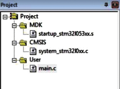
A distinctive feature of the new microcontrollers of the STM32L0 family based on the Cortex-M0+ core is the ability to dynamically change consumption due to a large number of innovations. One of these innovations was the appearance of Low Power peripherals: the 16-bit LPTIM timer and the LPUART transceiver. These blocks have clocking capabilities that are independent of the clocking of the main APB peripheral bus. If it is necessary to reduce power consumption, the operating frequency of the APB bus (PCLK) can be reduced, and the controller itself can be switched to low consumption mode. At the same time, Low Power peripherals continue to operate at maximum performance.
Let's consider an example from the Projects\LPUART\01_WakeUpFromLPM\ directory, which considers the possibility of independent operation of LPUART in low consumption mode.
When opening a project in the ARM Keil environment, only three files are displayed: startup_stm32l053xx.s, system_stm32l0xx.c and main.c (Figure 4). If the standard library were used, it would be necessary to add driver files to the project.
Functioning and analysis of the Main.c file structure
The selected example program is executed in several stages.
After the start, the SystemInit() function, implemented in system_stm32l0xx.c, is launched. It configures the parameters of the RCC clock block (timings and operating frequencies). Next, control is transferred to the main function int main(void). It initializes user peripherals - input/output ports, LPUART - after which the controller is switched to the STOP low-consumption mode. In it, the usual periphery and core are stopped, only LPUART works. It waits for the start of data transfer from the external device. When the start bit arrives, LPUART wakes up the system and receives the message. The reception is accompanied by flickering of the debug board LED. After this, the controller is switched back to the STOP state and waits for the next data transfer if no errors were detected.
Data transfer occurs using a virtual COM port and additional software.
Let's look at main.c from our project. This file is a standard C file. Its main feature is self-documentation - the presence of detailed comments, explanations and recommendations. The explanatory part contains several sections:
- a title indicating the file name, version, date, author, and a brief explanation of the purpose;
- description of the sequence of setting up system peripherals (RCC specific features): FLASH, RAM, power supply and clocking systems, peripheral buses, and so on;
- list of microcontroller resources used (MCU Resources);
- a brief explanation of how to use this example;
- a brief explanation of testing the example and the algorithm for its implementation (How to test this example).
The int main(void) function has a compact form and is equipped with comments, which in Listing 1, for greater clarity, are translated into Russian.
Listing 1. Example implementation of the main function
int main(void)
{
/* By the beginning of the execution of this part, when the system units have already been configured in the SystemInit() function, implemented in system_stm32l0xx.c. */
/* configuration of peripheral units */
Configure_GPIO_LED();
Configure_GPIO_LPUART();
Configure_LPUART();
Configure_LPM_Stop();
/* check for errors during reception */
while (!error) /* endless loop */
{
/* wait for LPUART to be ready and switch to STOP mode */
if((LPUART1->ISR & USART_ISR_REACK) == USART_ISR_REACK)
{
__WFI();
}
}
/* when an error occurs */
SysTick_Config(2000); /* setting the system timer interrupt period to 1 ms */
while(1);
}
The main.c file declares and defines peripheral configuration functions and two interrupt handling functions. Let's consider their features.
The example below uses four configuration functions (Listing 2). They all have no arguments and return no values. Their main purpose is to quickly and with the least amount of code required to initialize the peripherals. This is achieved through two features: the use of direct access to registers and the use of the __INLINE directive (Listing 3).
Listing 2. Declaring peripheral configuration functions
void Configure_GPIO_LED(void);
void Configure_GPIO_LPUART(void);
void Configure_LPUART(void);
void Configure_LPM_Stop(void);
Listing 3. Example implementation of the __INLINE function with direct access to LPUART registers
INLINE void Configure_LPUART(void)
{
/* (1) Enable power interface clock */
/* (2) Disable back up protection register to allow the access to the RTC clock domain */
/* (3) LSE on */
/* (4) Wait LSE ready */
/* (5) Enable back up protection register to allow the access to the RTC clock domain */
/* (6) LSE mapped on LPUART */
/* (7) Enable the peripheral clock LPUART */
/* Configure LPUART */
/* (8) oversampling by 16, 9600 baud */
/* (9) 8 data bit, 1 start bit, 1 stop bit, no parity, reception mode, stop mode */
/* (10) Set priority for LPUART1_IRQn */
/* (11) Enable LPUART1_IRQn */
RCC->APB1ENR |= (RCC_APB1ENR_PWREN); /* (1) */
PWR->CR |= PWR_CR_DBP; /* (2) */
RCC->CSR |= RCC_CSR_LSEON; /* (3) */
while ((RCC->CSR & (RCC_CSR_LSERDY)) != (RCC_CSR_LSERDY)) /*(4)*/
{
/* add time out here for a robust application */
}
PWR->CR &=~ PWR_CR_DBP; /* (5) */
RCC->CCIPR |= RCC_CCIPR_LPUART1SEL; /* (6) */
RCC->APB1ENR |= RCC_APB1ENR_LPUART1EN; /*(7) */
LPUART1->BRR = 0x369; /* (8) */
LPUART1->CR1 = USART_CR1_UESM | USART_CR1_RXNEIE | USART_CR1_RE | USART_CR1_UE; /* (9) */
NVIC_SetPriority(LPUART1_IRQn, 0); /* (10) */
NVIC_EnableIRQ(LPUART1_IRQn); /* (eleven) */
}
Interrupt handlers from the system timer and from LPUART also use direct access to registers.
Thus, communication with CMSIS is carried out without a standard library. The code turns out to be compact and highly efficient. However, its readability will deteriorate significantly due to the abundance of accesses to registers.
Using snippets in your own developments
The proposed sets of snippets have limitations: it is necessary to use the STM32L053 Discovery board for STM32SnippetsL0, and the STM32F072 Discovery board for STM32SnippetsF0.
To use snippets in your developments, you will need to make a number of changes. First, you need to reconfigure the project for the desired processor. To do this, you need to change the starting file startup_stm32l053xx.s to the file of another controller and define the required constant: STM32L051xx, STM32L052xx, STM32L053xx, STM32L062xx, STM32L063xx, STM32L061xx, STM32F030, STM32F031, TM32F051 and others. After this, when compiling stm32l0xx.h, the required file with the definition of the controller peripherals stm32l0yyxx.h will be automatically included (stm32l051xx.h/stm32l052xx.h/stm32l053xx.h/stm32l061xx.h/stm32l062xx.h/stm32l063). Secondly, you need to select the appropriate programmer in the project properties settings. Thirdly, change the code of the functions from the examples if they do not meet the requirements of the user application.
Conclusion
Sets of snippets and standard peripheral libraries produced by ST Microelectronics are not mutually exclusive. They complement each other, adding flexibility when creating applications.
The standard library allows you to quickly create clear code with a high level of abstraction.
Snippets allow you to improve code efficiency - increase performance and reduce the amount of occupied FLASH memory and RAM.
Literature
- Data brief. STM32SnippetsF0. STM32F0xx Snippets firmware package. Rev. 1. – ST Microelectronics, 2014.
- Data brief. STM32SnippetsL0. STM32F0xx Snippets firmware package. Rev. 1. – ST Microelectronics, 2014.
- MCD-ST Liberty SW License Agreement V2.pdfElectromechanical Relays. Technical Information. – ST Microelectronics, 2011.
- Data brief. 32L0538DISCOVERY Discovery kit for STM32L053 microcontrollers. Rev. 1. – ST Microelectronics, 2014.
- http://www.st.com/.
About ST Microelectronics
I indicated that the standard library is connected to the system. In fact, CMSIS is connected - the system of generalized structural representation of MK, as well as SPL - the standard peripheral library. Let's look at each of them:
CMSIS
It is a set of header files and a small set of code for unifying and structuring work with the core and periphery of the MK. In fact, without these files it is impossible to work normally with MK. You can get the library on the MK page.
This library, if you believe the description, was created to unify interfaces when working with any MK of the Cortex family. However, in reality it turns out that this is only true for one manufacturer, i.e. By switching to a microcontroller from another company, you are forced to study its peripherals almost from scratch.
Although those files that relate to the processor core of the MK are identical from all manufacturers (if only because they have the same processor core model - provided in the form of IP blocks by ARM).
Therefore, working with such parts of the kernel as registers, instructions, interrupts and coprocessor units is standard for everyone.
As for the periphery, the STM32 and STM8 (suddenly) are almost similar, and this is also partially true for other MKs released by ST. In the practical part, I will show how easy it is to use CMSIS. However, difficulties in using it are associated with the reluctance of people to read the documentation and understand the MK design.
SPL
Standard Peripheral Library - standard peripheral library. As the name suggests, the purpose of this library is to create an abstraction for the periphery of the MK. The library consists of header files where human-readable constants for configuring and working with MK peripherals are declared, as well as source code files collected into the library itself for operations with peripherals.
SPL is an abstraction over CMSIS, presenting the user with a common interface for all MCUs not only from one manufacturer, but generally all MCUs with a Cortex-Mxx processor core.
It is believed that it is more convenient for beginners, because... allows you not to think about how the peripherals work, but the quality of the code, the universality of the approach and the constraint of the interfaces impose certain restrictions on the developer.
Also, the functionality of the library does not always allow you to accurately configure the settings of some components such as USART (universal synchronous-asynchronous serial port) under certain conditions. In the practical part, I will also describe working with this part of the library.
A list of articles that will help even a beginner learn the STM32 microcontroller. Details about everything with examples ranging from LED blinking to brushless motor control. The examples use the standard library SPL (Standard Peripheral Library).
Test board STM32F103, ST-Link programmer, and software for firmware for Windows and Ubuntu.
VIC (Nested vectored interrupt controller) – interrupt control module. Setting up and using interrupts. Interrupt priorities. Nested interrupts.
ADC (analog-to-digital converter). Power supply diagram and examples of using ADC in various modes. Regular and Injected channels. Using ADC with DMA. Internal thermometer. Analog watchdog.
General purpose timers. Generating an interrupt at regular intervals. Measuring time between two events.
Signal capture by a timer using the example of working with an ultrasonic sensor HC-SR04
Using a timer to work with an encoder.
PWM generation. LED brightness control. Control of servo drive (servos). Sound generation.


