Radio amateurs SCM 24 what to do with it. Repair and adjustment of high-frequency units of black-and-white televisions. Receiver name
VHF-FM radio receiver
Currently, there are many Chinese-made radios on sale, which, due to low sensitivity, do not work equally well everywhere. However, it is not at all difficult to make a radio using ready-made blocks from old televisions. As practice shows, such receivers have a fairly high sensitivity, which is important for amateurs living far from the location of the antennas of transmitting stations, especially in mountainous areas. Such “free” stationary receivers are convenient to use in garages, workshops, boat stations, etc.
Televisions produced in the CIS used the principle of obtaining an intermediate audio frequency as the difference between the frequencies of the image carrier and the audio carrier; which is equal to 6.5 MHz. When receiving a television signal at the output of the channel selector, after conversion there are signals of intermediate frequencies of image fpchi = 38 MHz and sound fpchz-| = 31.5 MHz, from which the signal of the second intermediate sound (difference frequency) fпчз-|| = 6.5 MHz. It is clear that it is impossible to receive broadcast signals from the air, having only one audio carrier frequency without a second signal, to a television receiver, since it is a superheterodyne with double frequency conversion. If instead of the frequency converter we supply a 38 MHz signal from an additional generator to the circuit, we will be able to receive frequency modulation broadcasting stations (FM-FM).
In other words, to solve this problem it is necessary to manufacture an external local oscillator (a 38 MHz sinusoidal signal generator with high frequency stability) and apply a signal from it to the input of the UPCH. Tuning to the station is done using a tuning potentiometer by changing the voltage on the SK-M-24-2S varicaps.
It should be noted that if the power supply to the additional generator is turned off, the broadcast station will not be listened to.
The electrical circuit diagram of the additional generator is shown in Fig.1. This is a classic capacitive three-point with a QZ1 quartz resonator at 38 MHz. The circuit in the collector circuit of transistor VT1 is tuned strictly to the first harmonic of the frequency of this resonator using a tuning capacitor SZ.

Design data of generator circuit coils:
frame from television receivers UNT-47-III with a diameter of 8 mm (cylindrical screen);
L1 - circuit coil contains 10 turns of PEV-1 wire with a diameter of 0.5 mm with a tap from the 3rd turn (counting from the upper end of the coil).
L2 - communication coil contains 2 turns of PEV-1 wire with a diameter of 0.5 mm.
When making a contour, first L2 is wound at the bottom of the frame, and then L1. A carbonyl iron core of the SCR-1 type is inserted into the end of the L1 coil, which allows, if necessary, to change the inductance of the L1 coil.
A drawing of the 38 MHz generator printed circuit board is shown in Fig. 2, and the location of the parts is shown in Fig. 3. Dimensions of the printed circuit board are 67x43 mm.
The author made several stationary receivers from ZUSTST TVs, which were usually faulty. If space allows, for example in a garage, then all the necessary alterations can be made without completely disassembling the TV, right in its case.


Since the author uses the receiver from the TV only to listen to the sound of TV and radio broadcasts, the TV has removed power from the kinescope, the deflection system, the TVS with a multiplier and the horizontal scan transistor (KT838).
The meter channel selector (SK-M-24-2S) has a control socket “Out. IF" to which a prefabricated 38 MHz signal generator is connected via a 1.5 pF capacitor. Thus, the frequency from the additional generator will go to the radio channel submodule SMRK-2, where it will be used to obtain a difference frequency of 6.5 MHz. When receiving audio from television channels, the power to the external generator is turned off by an additionally installed switch.
Radio broadcasting stations are received in the TV range |-|| (TV channels 1-5), which corresponds to a frequency overlap of 49.75...99.75 MHz, but in practice the SK-M-24-2S receives signals with a carrier frequency of up to 107 MHz.
Despite the fact that radio broadcasting typically uses vertical wave polarization, a typical meter-wave television antenna will generally provide normal reception. Still, for better reception of distant radio stations, it is better to use a vertically polarized antenna or a regular television antenna, rotated 90°.
It should be noted that the sensitivity of such a receiver is quite high, and even with a telescopic antenna, under favorable conditions, many broadcasting stations are received.
If desired, the receiver can be assembled in a housing much smaller than the TV housing. In this case, it is enough to remove only one module from the TV for use - the radio channel module, for example, A1 MRK-2. On the board of this module, a UHF channel selector of type SK-D-24S, a MV channel selector of type SK-M-24-2S, a radio channel submodule SMRK-2, as well as a synchronization submodule USR are installed and interconnected. When receiving radio broadcasts and audio from television programs, the A1.4 (USR) board is not used and can be removed.
In order to simplify the receiver circuit, frequency tuning is carried out using a potentiometer connected to a rectifier with a voltage of 32 V. The potentiometer must have a linear characteristic of the dependence of resistance on the angle of rotation of the moving contact (group A).
The additional signal generator at 38 MHz is the same as described above. It connects to the SK-M-24-2S to the “Out. IF" through a capacitor with a capacity of 1.5 pF. From the output of the SMRK, the audio signal is fed to an audio frequency power amplifier (AMP). Any UMZCH with a sensitivity of about 70 mV can be used. You can also use the UMZCH on the K174UN7 chip from the same TV, which is located on the A9 board (BU-2-2 control unit). The UMZCH is supplied with a supply voltage of + 12 V. The contact numbers of the A1 board connectors for connecting power, turning on ranges, supplying setting voltage and low-frequency signal output are shown in the block diagram of Fig. 4.

Using the SA1 switch, we select the desired range, and when receiving broadcast stations, it is necessary to turn on the SA2 switch (“PB”) and supply power to the 38 MHz generator, and when receiving audio from television programs, the SA2 switch must be turned off (in the “TV” position),
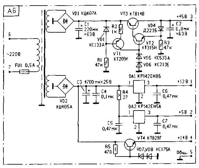
The receiver, assembled from blocks from the TV and two additional circuits, is powered by a stable voltage of +12 V and +32 V (to change the capacitance of the varicaps) from the power supply, the circuit of which is shown in Fig. 5.

This power supply uses a power transformer T1 type TC40-2, the half-windings of the secondary windings of T1 must be turned on according to the diagram in Fig. 5.
In principle, in this power supply unit you can use any power transformer with a power of 20...30 W with suitable voltages on the secondary windings of 12.5...14 V and 18...20 V.
The power supply circuit has no special features. To power the UMZCH and the radio channel, a bridge rectifier using diodes VD3-VD6 is used, and a voltage doubling circuit using diodes VD1, VD2 is used to control the varicaps. The supply voltages are stabilized by simple stabilizers. To compensate for the voltage drop across transistor VT2, a diode VD11 is introduced into the circuit.
Literature
1. Kuzinets L.M., Sokolov V.S. Television receiver units. Directory. - M.: Radio and communication, 1987.
2. Schematic diagram of the TV Photon 381D.
S.Babyn. village Kelmentsi, Chernigov region.
Source:
Download: Stationary VHF-FM radio receiver made from modules from old TVs
If you find broken links, you can leave a comment, and the links will be restored as soon as possible.
Other news
Radio broadcasting in the VHF bands allows radio listeners to be provided with a higher quality sound signal compared to broadcasting in the long, medium and short wave bands. Moreover, the struggle for reception quality has led to the emergence of industrial and amateur radio receivers exclusively for reception in the VHF bands.
We present to our readers one of these amateur developments. And although the author calls his design complex, we are not inclined to dramatize the assessment. Let's just say that improving the quality of work (good stereo in two standard formats) also requires certain costs.
The described receiver design is intended for listening to broadcast stereo and monophonic VHF-FM radio stations in the range of 65.8...74 MHz and 88...108 MHz, as well as the sound of television broadcasts on all MB and UHF channels.
It is possible to receive stereo programs with both polar modulation and pilot tone. You can pre-program the receiver's memory for 55 radio stations and, if necessary, quickly select any of them using the remote control or directly the buttons on the front panel of the receiver. Volume and stereo balance are also adjustable both remotely and from the control panel. The number of the received channel and all the necessary information during setup is displayed on a two-digit seven-segment indicator.
The proposed design is an attempt to create an easy-to-use device suitable for high-quality stereo reception in areas with a large number of television and VHF-FM radio stations. Despite the relatively complex circuit, the receiver is easy to set up and operate. It is assembled from available parts and consists of several functionally complete blocks assembled on separate boards. This allows you to easily make any changes and additions to it when repeating the design.
The receiver is made according to a double frequency conversion circuit. The signal received by the antenna is converted into the first IF by a standard television channel selector type SK-V-418-8. You can also use SK-V-41 or any imported one, designed to operate in the MB, UHF and KATV (cable television) bands 110,..174 MHz. It is not recommended to use outdated SKM-24 type selectors, since they do not cover the range of 100...108 MHz and have lower gain.
As is known, any superheterodyne receiver, in addition to the main channel, also has out-of-band reception channels at mirror and intermediate frequencies, as well as due to conversion at harmonics and subharmonics of the local oscillator frequency, i.e. reception on frequencies
fnp=mfg ± nfc,
where m, n = 1, 2, 3... ; fnp - intermediate frequency; fg - local oscillator frequency; fc - signal frequency.
The receiver has two local oscillators, so there are even more out-of-band channels in it, since the local oscillator signals can interact with each other on the nonlinear elements of the device. Of course, the vast majority of these side channels are filtered out by the input channel selector circuits and the first and second IF bandpass filters.
However, it is still recommended to select the local oscillator and IF frequencies so that the combination frequencies do not fall within the frequency range of the useful signal. In other words, so that there are no affected points near the radio stations received in the given area. This is achieved by choosing the value of the first IF, which should lie within the frequency range of 32.5...38 MHz. In the author's version, the first IF is 32.8 MHz (IF1).
From the output of the channel selector, the IF1 signal is fed to the input of the IF-FM block (A2). Its diagram is shown in Fig. 1. After cascade amplification at VT1 and a dual-circuit bandpass filter L1 - L3, C4 - C8, the signal is fed to the second frequency converter, made on the DA1 chip. A local oscillator with an oscillating circuit on L4, C10 - C 13 operates at a frequency of 22.1 MHz. The second IF is standard - 10.7 MHz (IF2). It is allocated on the L5C15 circuit, passes through the main selection filter ZQ1 and enters the input of the multifunctional chip DA2. The filter must have a bandwidth of 250...300 kHz. You can use a concentrated selection filter like FP1P-0496 or any imported one.

Fig.1 (click to enlarge)
The OD2 microcircuit is connected according to a standard circuit and carries out the main amplification, limitation and demodulation. In addition, it generates the APCG voltage and a setting signal (“Setup”), supplied to the control unit. Upon receipt of this signal, the control unit reduces the receiver's tuning speed to facilitate accurate pre-tuning to the station. From the control unit, the signal “Block. APCG” comes to pin 2 of the DA2 microcircuit, which turns off the APCG while the receiver is being rebuilt.
The demodulated low-frequency signal from pin 7 of the DA2 microcircuit through resistor R22 is supplied to the input of the stereo decoder block (A3). The diagram of this block is shown in Fig. 2. A pre-amplifier is assembled using transistors VT1, VT2. The adjusted resistors R5 and R6 are designed to select the optimal input signal level for the stereo decoder chips DA2 and DA1, respectively.

Rice. 2 (click to enlarge)
The stereo decoder for a signal with polar modulation according to the 01 RT system (frequency range 65.8...74 MHz) is made on a DA1 chip of type K174XA14. It is not recommended to use the more modern design of the K174XA35, since in real signal conditions it works very unstable, with clicks that are very noticeable to the ear, and constantly switches from the “Stereo” mode to the “Mono” mode. The stereo decoder on the K174XA14 chip works much more stable. It is assembled according to the scheme described in detail in.
The stereo decoder for a signal with a pilot tone according to the CCIR system (frequency range 88 ... 108 MHz) is assembled on a DA2 chip of type TA7342P, also according to a standard circuit. Stereo decoders are switched using the “PM/Pilot” signal supplied from the control unit. When this signal is high, transistor VT3 is open and transistor VT4 is closed and the supply voltage is supplied to the DA1 chip. When the signal level is low, power is supplied to the DA2 chip and disconnected from the DA1 chip.
Both microcircuits used have an automatic built-in Mono-Stereo switch, so forced activation of the Mono mode is not provided. To switch to this mode, simply turn on the “wrong” Stereo Decoder. For example, to receive a station using a polar modulation system in monaural mode, you need to turn on the Stereo Decoder for the pilot tone system. Of course, by somewhat complicating the circuit of block A3, you can implement forced inclusion of “Mono”. However, as operational practice has shown, this is not necessary. The output signals of stereo decoders are fed to the input of the filter block and electronic volume control A4. Its diagram is shown in Fig. 3.

rice. 3 (click to enlarge)
A pre-amplifier is assembled on the DA1 K548UN1 chip. Its purpose is to normalize signal levels from the outputs of stereo decoders. As DA1, it is permissible to use any low-noise op-amp in a standard connection. The DA2 chip contains an active filter for suppressing the remaining subcarrier frequencies of a complex stereo signal. In the absence of the K174UN10 microcircuit, the filter can be assembled according to any other scheme, for example, as recommended in.
The electronic volume and stereo balance control is assembled on the DA3 chip of the A4 block according to a standard circuit. The control voltage is supplied to pins 13 and 12 of this microcircuit from the control unit. The signal from the outputs "Output 1A" and "Output 1B" is fed to an external connector for recording to a tape recorder. Its level is independent of volume control. From the outputs "Out. 2A" and "Out. 2B" the signal is supplied to a power amplifier and to a connector designed for connecting an external high-quality final ULF.
The receiver power amplifier (A5) is made on the K174UN14 microcircuit. It does not have any special features. The diagram of one amplifier channel is shown in Fig. 4.

rice. 4
The power supply (A6) is assembled according to a transformer circuit; its diagram is shown in Fig. 5.
rice. 5
The receiver control unit (A7) is based on the KR1853VG1-03 “television” controller. Its diagram is shown in Fig. 6. Basically, it repeats the scheme of the CH-44 tuning system for domestic 4th generation TVs. The differences lie in the exclusion of the standby mode and in the range decoder circuit.

rice. 6 (click to enlarge)
The decoder is made on a DD3 chip and transistors VT7 - VT9. The need for such a complication of the circuit is explained by the fact that in the controller the rate of change of the tuning voltage is different in different ranges. A radio signal occupies a much smaller frequency band than a television signal, therefore the tuning speed across the range should be less. In the proposed scheme, range 1-2 of the controller is not used, range 3 corresponds to the frequency band 50... 100 MHz, range 4-5 - 100...230 MHz, and range H - UHF.
The ranges are displayed on the indicator as shown in Fig. 7: a) - voltage at the lower end of the range 50... 100 MHz; b) - in the center of the range 100...230 MHz; c) - at the upper end of the UHF range. The upper dashes of the indicator are used in the mode to display the tuning voltage in three levels. The HL1 indicator block has a circuit for connecting elements with a common anode, any type of indicator, for example KIPTS09I-2/7K.

rice. 7
For remote control, a standard RC-44 (RC-401) remote control for 4th generation TVs is used. This remote control is made on the basis of the IRT1260 microcircuit from ITT, which has a domestic analogue KR1056HL1. The purpose of the local keyboard buttons is shown in the table. The corresponding remote control buttons perform a similar function.
The temperature coefficient of the zener diodes VD6 and VD7 (see Fig. 6) determines the stability of the receiver tuning. In the author's version, the best thermal compensation of the local oscillator frequency was obtained by using four zener diodes connected in series - two D814B and two KS191F. The KR1853VG1-03 microcircuit is an analogue of the SAA1293A-03 from ITT, the KR1628RR2 is MDA2062, the input amplifier of the IR remote control TVA2800 has domestic analogues of the KR1054UI1, KR1054KHAZ, KR1056UP1, KR1084UI1. Pin numbers in Fig. 6 are shown for KR1628RR2 and TVA2800 microcircuits in a package with 14 pins. For a 16-pin case, the numbers of pins from 8 to 14 should be increased by 2. Buttons SB1 - SB12 - for short-circuiting without fixation.
The receiver interconnect diagram is shown in Fig. 8.

rice. 8 (click to enlarge)
Chokes L1 - L7 are ferrite tubular magnetic cores placed on the corresponding conductors. You can use magnetic cores made of F600 ferrite from DM-0.1 chokes. DM-0.1 with an inductance of 500 μH was used as chokes L8 and L9. LEDs HL1 - HL3 are located on the front panel of the receiver, HL1 indicates tuning to a station, and HL2 and HL3 indicate the presence of a stereo signal via a system with polar modulation and pilot tone, respectively. Elements C1 - C4, R1 - R4, L1 - L9 are mounted mounted on the terminals of blocks A1, A5 and A7. Connectors X2 and X3 type ONTs-KG-4-5/16-R are intended for connecting the inputs of a tape recorder and an external UMZCH, respectively. They are located on the rear wall of the receiver. IX1 is also located there for connecting 220 V power and X4, X5 for connecting speaker systems of channels A and B.
This design is designed to be repeated by sufficiently qualified radio amateurs, so drawings of printed circuit boards are not provided. When placing parts on boards, you must adhere to the general rules for installing high-frequency structures. Inside the housing, the boards should be placed in such a way that the channel selector and the IF-FM unit are at the maximum distance from the control unit. Regulating transistors and microcircuits of stabilizers and power amplifiers should be mounted on the radiator as far as possible from the high-frequency units and the stereo decoder unit.
All contour coils in the IF-FM unit are wound with 0.28 mm PEV wire on frames with a diameter of 7 mm with trimmers made of F100 ferrite. Such frames were used in the circuits of the KB bands of the OCEAN receiver. The communication coils are wound with 0.1 mm PEV wire on top of the corresponding contour coils. All oscillatory circuits are enclosed in brass or aluminum screens.
Number of coil turns: L1 - 3+3, L2 - 6, L3 - 3, L4 - 10, L5 - 6+6, L6 - 5, L7 - 6.
The elements of the block of stereo decoders C6, R7, R8, according to the reference data for the K174XA14 chip, must be selected with an accuracy of ±1%, but without much damage to quality, it is quite possible to use the nearest standard value. Capacitor C12 is non-polar. If there is no capacitor of the required capacity, it can be made up of three K10-47 (option a).
|
No. block button A7 (Fig. 6) |
Standard |
Receiver name |
Function performed |
|
SETTINGS+ |
Increasing tuning voltage |
||
|
Forced activation of "MONO" mode (not used) |
|||
|
RANGE |
Range selection |
||
|
SETUP- |
Reducing tuning voltage |
||
|
Stereo balance right-left |
|||
|
Stereo panel left-right |
|||
|
Polar modulation/pilot tone system switching |
|||
|
VOLUME- |
Decrease volume |
||
|
VOLUME+ |
Increase volume |
||
|
PROGRAMS- |
Searching channels downwards |
||
|
PROGRAMS+ |
Searching channels upward |
Capacitors C9 and C30 determine the frequency of the VCO of the microcircuits, so they should be with the lowest TKE possible. Of the older types, we can recommend KSO-G. There are no special requirements for the remaining elements of the block.
The installation of block A2 IF-FM has no special features and is carried out according to standard methods. Capacitor C9 must be soldered directly to pins 12 and 1 of the K174XA6 microcircuit from the side of the printed conductors.
Setting up the A3 stereo decoder block involves adjusting the VCO frequency with resistors R9 and R29 until the frequency is reliably captured by the subcarrier PLL system of the microcircuits. This moment is determined by the lighting of LED HL2 or HL3. Resistors R5 and R6 achieve the same level of signals at the output of stereo decoders.
In the control unit, it is necessary to set the options in the non-volatile memory DD2. This is done in service mode only with the remote control. To enter this mode, you must press and hold the “SERVICE” button on the remote control for 0.5 seconds. After the "CH°" symbols appear on the indicator, release and press this button again. After the "OP" symbols appear, you need to select the option number on the left indicator using the "Volume+" or "Volume-" key, and then set or reset the corresponding option bits on the right indicator using the numeric keys of the remote control. All necessary settings are shown in Fig. 9.
rice. 9
After programming each byte of options, press the "MEMORY" key of the remote control to write information into non-volatile memory.
Pre-tuning of radio stations is carried out similarly to tuning of a 4th generation TV with the CH-44 tuning system. First, you need to select a band using the "RANGE" button, then use the "SETUP+" or "SETUP-" button on the remote control or local panel to tune to the desired station, and select the appropriate system with the "PM/Pilot" button. At this time, the indicator begins to blink. The activation of the stereo decoder for a system with polar modulation is indicated by a luminous dot on the right acquaintance of the indicator. Then, using the “PROGRAMS-” or “PROGRAMS+” button, select the channel number for the station ranging from 1 to 55. You can also use the numeric keys on the remote control. To memorize information, you must press the "MEMORY" key, and the indicator stops blinking. In the future, tuning to the programmed stations is carried out by searching the channels upward or downward using the “PROGRAMS+” or “PROGRAMS-” button, respectively. From the remote control you can directly enter the channel number using numeric buttons. The position of the volume and stereo balance controls is also stored in non-volatile memory when the "MEMORY" button is pressed.
The operation of the KR1853VG1-03 controller and the setup procedure are described in more detail in and.
The total consumption from sources +5 V, +12 V, +14 V is no more than 0.6 A, and from a source of +45 V - 0.05 A.
Literature
- S. Chepulsky. Stereo decoder in the radio receiver "ISHIM-003-1". - Radio Amateur, 1994, No. 12, pp. 15-18.
- P. Belyatsky. Stereo signal decoder. - Radio, 1996, No. 3, pp. 26,27
- Integrated circuits. Microcircuits for television and video equipment, vol. 2 - M.:DODEKA, 1995.
- Elyashkevich S.A., Peskin A.E. Fifth generation TVs. Directory. - M.: KUBK-a, Symbol-R, 1996.
See other articles section.
Read and write useful
Repair and adjustment of high-frequency units of black-and-white TVs
The channel selector (SC) is designed for selection, amplification and conversion of high-frequency signals into intermediate frequency signals. The SC includes a high-frequency amplifier, a mixer and a local oscillator.
According to their design features, channel selectors can be divided into tube television channel switches (PTK); transistor selectors with mechanical channel switching; transistor selectors with electronic adjustment.
The qualitative parameters of the SC are characterized by: voltage gain - the ratio of the voltage at the output load of the channel selector to its input voltage, expressed in decibels; Frequency response determined by the parameters of input circuits and UHF bandpass filters; instability of the local oscillator frequency during warm-up, caused by the deviation of the local oscillator frequency during a certain warm-up time of the SC.
Let's consider the circuit design of the SC. All tube television channel switches (PTS) contain a 12-section drum switch, each sector of which corresponds to 12 television channels.
An SK-D unit can be connected to PTK-11D, which provides reception of TV broadcasts in the decimeter wavelength range (band III), while the PTK mixer is used as an additional intermediate frequency amplification stage. The design of the meter channel selector (SCM) is similar to the design of tube PTCs, but the SCM, used in portable TV modules to reduce size, has a dial switch for television channels (SCM-20). In Fig. 7.3, and shows a schematic diagram of SKM-15, designed for all classes of black-and-white and color televisions, made using transistors.
The antenna is connected to the input circuit L7, L8, C4^C5 through a filter LI, Cl, L2, C2, L3, SZ, L4, which serves to provide the necessary noise immunity via the forward channel. The high-frequency amplifier is assembled on transistor VT1 according to a circuit with a common base. UHF uses specially designed high-frequency transistors GT328, which have a pronounced dependence of the gain on the emitter current. The AGC voltage is supplied to the base circuit of transistor VT1. The local oscillator is made on transistor VT3 according to a capacitive three-point circuit. The transistor mode is set by resistors R8, Rll, R19, R10 and zener diode VD1. The APCG voltage is supplied to the varicap VD2, partially connected to circuit L11 through capacitor 016. Transistor VT3 is connected according to a common base circuit. The SKM mixer is made on transistor VT2 according to a common emitter circuit. The local oscillator and UHF signal is supplied to the base of the transistor; an L6C22 intermediate frequency filter is included in its collector circuit. When receiving in the DCV range, the signal from the ACS through the bandpass filter C27, L5, C26, C25 is supplied to the base of the transistor VT2. The mixer in this case serves as an additional cascade of the UPCH, and the power to the UHF and the SCM local oscillator is turned off.
Television channel selectors with electronic adjustment are similar to those described. They use smooth adjustment of circuits with varicaps and switching ranges with diodes. Note that a twofold construction of the SCM is possible. In the first case, amplification and conversion of signals is carried out by a common path in frequency ranges I, II and III (for example, SKM-18, SKM-30, SKV-1), in the second, separate paths are used for ranges I, II and III, the mixer remains common (for example, SKM-23, SKM-24).


Let's consider the construction of SCM 24-2 (Fig. 7.3, b). Signals in bands I and II are amplified by UHF, collected on transistor VT2 according to a common base circuit, signals in band III are amplified by UHF, collected on transistor VT1. Heterodynes of ranges I, II and III are made, respectively, on transistors VT4 and VT5 according to the circuit of three-point capacitors with a common base. For both amplification paths on transistor VT3, the mixer is common. The ranges are turned on by applying voltage to the emitters of the transistors of the corresponding path. The circuits of idle SCM cascades and the mixer inputs are turned off by diodes VD3, VD4, VD9, VD11. UHF of both bands are controlled by AGC voltage. To reduce interference along the forward channel at the intermediate frequency, a filter LI, C1, L3, C2, L4, SZ, L5, L6, C4 is included at the SCM input. The SKD is turned on by the VD10 diode, while the power from the UHF and local oscillators is turned off, and the SKM mixer serves as the first stage of the UPCH.
The SKM SKV-1 and SKM-30 use a common AMP for all ranges, controlled by the AGC voltage. The mixer is designed similarly to the SKM-24 (as is the local oscillator). Switching ranges is carried out by switching selective circuits with diodes. SKM-30 differs from the previous ones in the construction of UHF, which is made according to a cascade circuit OE - OB on two transistors.
UHF channel selectors are designed to amplify and convert TV broadcast signals in the UHF range into intermediate frequency signals and work in conjunction with SCM. In the SKD, the local oscillator is combined with a mixer. The tuning element can be variable capacitors or varicaps. Examples of SKD with mechanical adjustment are SKD-1, SKD-20. Electronic tuning is used in SKV-1, SKD-23, SKD-24, SKD-30. At frequencies in the decimeter range, resonant systems cannot be constructed on conventional circuits, therefore half-wave or quarter-wave long lines are used in ACS units for selective circuits. When using segments of half-wave lines, a tuning element can be connected to one end of the line, and an active element (transistor) can be connected to the second. One end of the quarter-wave segment of a long line is grounded, and the other is loaded with a tuning element and a transistor. Note that quarter-wave lines make it possible to reduce the dimensions of the ACS unit. SKD with half-wave asymmetrical long lines includes SKD-24 (Fig. 7.3, c).

The high-frequency amplifier is made on transistor VT1 according to a circuit with a common base. The AGC voltage is supplied to the base circuit through resistor R3. At the UHF input, a filter L1, C1, L2 is included, which provides filtering of signals from television stations in the meter wavelength range. The UHF output is loaded onto a bandpass filter L6, L10, connected to ground by capacitors CIO, C12. On the other hand, the lines are adjusted by varicaps. The mixer is made combined with a local oscillator based on transistor VT2 with similar adjustment elements. The pairing of the UHF and local oscillator circuits is ensured by selecting the capacitance-voltage characteristics of the varicaps VD2, VD3, VD4. Structurally, all types of SKD are made in a metal case, consisting of five sections, closed with common metal covers.
All wave selectors (SKV-1, SKV-2) combine SKM and SKD in one housing. Their circuit design is similar to that of the described SCM and SKD.
The operation of electronically tuned channel selectors is controlled by electronic program selection and switching devices. Program selectors (PSS) are divided into three types: touch, pseudo-touch and push-button.
Defects in PTC, SCM and SKD manifest themselves in basically the same way. If the unit malfunctions, the image and sound disappear. Sometimes there is no sound when there is a picture and vice versa. The image may be very noisy, there may be no reception on any one channel or band (for SCM with electronic tuning).

A typical malfunction that often occurs in high-frequency units PTK, SKM-15, SKM-20 is that the image and sound appear when the switch knob is pressed or turned. This defect is associated with deterioration of contact in the channel switch and can be eliminated by removing the block, disassembling it, washing (with alcohol, acetone) the drum contacts and the spring petals of the contact strip, followed by assembling the block. Washing the contacts does not always lead to the desired result; in this case, it is recommended to bend the petals of the contact strip and clean the contact groups with a pencil eraser. The troubleshooting algorithm for PTC, SCM and SKD (Fig. 7.4, a) is based on the method of sequential intermediate measurements.
The TV channel selector is adjusted after replacing faulty parts, which usually does not cause a significant detuning of the unit’s characteristics. Changes in the installation design associated with repairs may affect the unit parameters. Regulation of PTC, SCM and SKD is carried out using an frequency response meter, a signal generator and a PNP-3 device (PTK adjustment device). A block diagram of switching on devices for setting TV channel selectors and measuring from parameters is shown in Fig. 7.4, b.
The frequency response image is obtained on the oscilloscope screen or IFC screen after detecting the intermediate frequency signal. The IFC includes a detector section, and the PNP-3 device includes a load equivalent and an intermediate frequency signal detector. An equivalent load is required if channel selectors are configured without specialized devices. In general, the equivalent load for tube selectors is high-impedance (Fig.
7.5, a), for transistor selectors - low-resistance (Fig. 7.5, b).
When working with an IFC or sweeping frequency generator, it is necessary to match the high-frequency output of the device and the input of the TV channel selector. When setting up, it is not advisable to connect the generator and the channel selector with a cable, since the observed shape of the frequency response depends on its length and location (the traveling wave mode is not implemented in the cable). The IFC generator must be turned on through a matching device (Fig. 7.6) or an attenuator with an attenuation of 9.5 dB. In this case, the value of the input voltage (Lx = (Len /3.

Setting up and adjusting channel selectors involves a set of works to check and set the required amplitude-frequency characteristics of the block stages and its end-to-end characteristics, setting the nominal frequency of the local oscillator and the selector gain. The setup is carried out in the following sequence: initially, the IF circuit is set up, then the input IF signal suppression circuit is set, the nominal frequency of the local oscillator is set, the input circuits are adjusted and the frequency characteristics are corrected on each TV channel, starting from the highest.
By connecting the channel selector to a power source and assembling a circuit similar to that shown in Fig. 7.10, adjust the output circuit of the inverter until the required characteristic is obtained (Fig. 7.7, a). The signal from the output of the IFC sweep frequency generator is fed to the KT-1 control point (SKM-15, PTK-PD) through a capacitor with a capacity of 5-6 pF, the output is connected through the detector to the IFC input. Tube PTCs are characterized by a double-humped frequency response.
The local oscillator is configured as follows. By simultaneously applying the RF signal from the IFC and the carrier frequency signal of the tuned TV channel from the high-frequency generator to the input of the channel selector, set the voltage on the varicap to 5 V and adjust the local oscillator circuit with the core until the generator frequency conversion mark aligns with the 38 MHz frequency mark on the IFC screen . Having aligned the marks, check the effect of frequency adjustment by changing the voltage on the varicap. The local oscillator frequency should be offset by ± 1 MHz from the carrier. The frequency response of the RF frequency response is observed by connecting the IFC input to the KT-2 (SKM-15) control point (Fig. 7.7, b). If the characteristics do not match, adjust the input circuit or the UHF selector bandpass filter. The selector gain is determined by changing the IFC generator signal by 10 times using an attenuator, and then the resulting frequency response is measured with and without an attenuator:
Where U is the average amplitude of the end-to-end characteristic; Ua-amplitude of the frequency response with the attenuator turned on.
Adjustment of channel selectors with electronic settings is carried out in the same sequence
The schematic diagram of channel selectors SK-D-24 and SK-M-24 is shown in the figures below.
Channel selector SK-D-24
UHF channel selector SK-D-24 032.222.016 is designed for selection, amplification and conversion of UHF television radio signals into intermediate frequencies.
Main technical data and characteristics:
- Frequency range. MHz.... 470 - 790;
- Noise figure, dB. no more.... 11.5;
- Gain, dB. no less than.... 7;
- Rated supply voltage, .... V 12;
- Voltage limits of the varicap control circuit, .... V 0.6 - 25.2 V;
- AGC rated voltage. AT 8;
- Current consumption, mA, no more.... 15;
- Weight, kg, no more.... 0.12;
- Overall dimensions, mm, no more.... 93 * 61 * 25;
- Content of precious materials: gold - 0.0234 g; silver - 0.0646 g.
Rice. 1. Schematic diagram of the channel selector SK-D-24.
Channel selector SK-M-24
The meter range channel selector SK-M-24 0E2.222.015 is designed for selection, amplification and conversion of meter range television radio signals into intermediate frequency.
Main technical data and characteristics:
- Frequency range, MHz 4.... 8.5 - 230;
- Noise factor, dB, no more than.... 9.5;
- Gain, dB, not less.... 15.5;
- Rated supply voltage, V.... 12;
- Voltage limits of the varicap control circuit, V.... 0.6 - 25.2;
- Rated voltage of AGC, V.... 8;
- AGC control depth, dB, not less.... 24;
- Current consumption. mA. no more than.... 25;
- Cash register, kg, no more.... 0.160;
- Overall dimensions, mm, no more.... 97 * 85.5 * 25;
- Content of precious materials: gold - 0.0361 g, silver - 0.232 g.

Rice. 2. Schematic diagram of the SK-M-24 channel selector.
Connection diagram for SK-D-24 and SK-M-24 modules

Rice. 3. Connection diagram for channel selectors SK-D-24 and SK-M-24.
VHF RADIO AND TELEVISION SOUND RECEIVER Nowadays in radio parts stores there is a very large, simply huge, selection of various construction kits for homemade radio amateurs. Among them there are quite a few kits for assembling UHF radio receivers, but despite the variety of prices and names, almost all of them are made on the basis of the K174XA34 microcircuit and its analogues. And the difference, let’s say, is in the configuration. There are kits only for the radio circuit, some with bass amplifiers, stereo decoders and even synthesizers for tuning.
Typically, these receivers are designed to operate in one of the radio broadcast bands, less often in two, and there are no options at all that can receive not only radio broadcasts, but also television audio. This is not surprising, since the upper ceiling for the K174XA34, if I’m not mistaken, is 150 MHz.
Using one of these kits and an analog all-wave tuner from a TV, you can make an all-wave VHF receiver that can receive not only radio broadcasting stations, but also television audio. The operating frequency range of the all-wave TV tuner extends from 48 to 790 MHz. If this is an all-wave tuner with a continuous range of at least MB (48-230 MHz), then, as you can see, the broadcasting ranges of 64-73 MHz and 88-108 MHz also fall into its range. Why, then, cannot an ordinary TV with such a tuner be tuned to a broadcast station? The answer is simple, in the TV circuit, the IF image signal is used as the local oscillator frequency to generate the second IF sound. If there is no IF image, then the second IF sound is not generated. If you plan to receive only sound, then there is no need to even take into account the image signal at all. There are two signals at the output of the TV tuner, the first IF audio signal and the IF image signal. These signals in the TV circuit go first to the SAW IF filter, and then to the IF path, where the output is a video signal and a second IF audio signal.
In our case, it is enough to use only the signal of the first IF sound, feeding it to the input of a VHF-FM receiver configured to receive a signal with a frequency of 31.5 MHz.
As a matter of fact, you can take any VHF-FM receiving path, for example, based on the K174XA34 microcircuit, and make it fixed at 31.5 MHz.
Moreover, the circuit is generally extremely simplified, since in the local oscillator you can use a ready-made circuit to the first IFB from the TV, just connect it instead of the local oscillator circuit. And the input circuit is not needed at all, since the output of the TV tuner already has an IF circuit, and it will work as the input circuit of the VHF receiving path. Thus, an all-wave VHF-FM superheterodyne with double frequency conversion is obtained.
The schematic diagram of the receiver is shown in the figure. The basis was a set for a VHF-FM stereo tuner using the KR174XA34 IC as a receiving path and the TDA7040T IC as a stereo decoder. Compared to the receiver circuit from the kit, this circuit is significantly simplified, since there is no need for an input circuit, and the local oscillator circuit with a varicap and a multi-turn variable tuning resistor is replaced by one circuit of the first IF, plus a tuning capacitor C16 with which this circuit is adjusted to frequency 31, 5 MHz.
The functions of the first frequency converter are performed by the all-wave television tuner A1 KS-H-1350. This is a tuner with analog control (tuning to the frequency is done by changing the voltage on pin 2, and switching ranges by switching the +5V voltage between pins 3, 4, 5). Here you can use any similar tuner that covers not only television bands, but VHF-FM, for example, SKV-41 or SKV-418, turning it on according to the standard circuit. Old domestic selectors such as SKM-24 and SKD-24 are suitable only if you do not plan to receive radio broadcasts, but only listen to the sound of television programs (in this case, there is no point in a stereo decoder). You can use another tuner besides those listed above, but it must be analog, that is, one to which you need to apply a varying tuning voltage and switch ranges by switching the voltage between three pins. Tuner controlled digitally


