How does the LCD display work? LCD monitors
Liquid crystals were discovered back in 1888. But they found practical application only thirty years ago. “Liquid-crystalline” is the transition state of a substance in which it acquires fluidity, but does not lose its crystalline structure. The greatest practical interest, as it turns out, is the optical properties of liquid crystals. Thanks to the combination of a semi-liquid state and a crystalline structure, the ability to transmit light can be easily changed.
Types of LCD matrices
The first mass product using liquid crystals was an electronic watch. The monochrome display consisted, as is known, of individual fields filled with liquid crystals. When a voltage is applied to order the crystals, the desired fields block the passage of light and appear black against a light background. Color displays appeared when the cell sizes were significantly reduced and each cell was equipped with a color filter. In addition, modern LCD monitors use backlighting.
For illumination, 4 or 6 lamps and mirrors are usually used to ensure uniformity. The operation of an LCD panel is based on the polarization of light. In the path of the light flux there are two polarizing films with perpendicular polarization directions. That is, in total, these two films block all the light. Liquid crystals located between the films reverse part of the flow polarized by the first film and thus regulate the glow of the screen.

LCD matrix subpixel circuit.
Each pixel is made up of blue, red and green subpixels
A layer of liquid crystalline substance is “sandwiched” between two guide films with tiny notches, in the direction of which the crystals line up. You can change the orientation of the crystals, for example, using an electrical pulse, as is done in the matrices of LCD monitors. In modern matrices, each cell has its own transistor, resistor and capacitor. Actually, in color matrices, each pixel represents three cells: red, green and blue.
Matrix TN. The oldest and most common
The oldest type of matrices that are currently used is TN. The name of the technology stands for Twisted Nematic. Nematic liquid crystalline substances consist of elongated crystals with spatial orientation, but without a rigid structure. Such a substance is easily susceptible to external influences.
In TN matrices, the crystals are aligned parallel to the screen plane, and the upper and lower layers of crystals are rotated perpendicular to each other. All the rest are “twisted” in a spiral. Thus, all transmitted light is also twisted and passes unhindered through the external polarizing film. So when the TN matrix cell is turned off, it glows, and when voltage is applied, the crystals gradually rotate. The higher the voltage, the more crystals unfold and the less light passes through. As soon as all the crystals turn parallel to the light flux, the cell “closes”. But for TN matrices it is very difficult to achieve perfect black.

The crystals in the TN matrix are “twisted” in a spiral (1).
When voltage is applied, they begin to rotate (2).
When all the crystals are perpendicular to the surface (3), no light passes through.
The main problem of TN matrices is the inconsistency in the rotation of the crystals: some are already completely rotated, others have just begun to rotate. Because of this, the light flux is scattered and, ultimately, the picture does not look the same from different angles. Horizontal viewing angles of modern matrices can be considered acceptable, but when rotated vertically, even within small limits, the distortion is significant. The color rendering of TN matrices is far from ideal - they, in principle, cannot display the full palette of colors; I compensate for the lack of shades using cunning algorithms. Such algorithms, with a frequency invisible to the eye, alternately reproduce in the cell the shades closest to the one that cannot be reproduced. But TN technology provides maximum cell response speed, minimum power consumption and is as cheap as possible. These two circumstances make the oldest technology the most popular and most widespread.
IPS. Ideal for photos and graphics. But expensive
The second most developed technology was IPS (In Plane Switch). Such matrices are produced by Hitachi and LG.Philips factories. NEC produces matrices made using similar technology, but with its own abbreviation SFT (Super Fine TFT).
As the name of the technology suggests, all crystals are located constantly parallel to the panel plane and rotate simultaneously. To do this, it was necessary to place two electrodes on the underside of each cell. When turned off, the cell is black, so if it is dead, there will be a black dot on the screen. And not constantly glowing, like TN.

In an IPS matrix, the crystals are always parallel to the screen surface
IPS technology provides the best color reproduction and maximum viewing angles. Significant disadvantages include a longer response time than TN, a more noticeable interpixel grid, and a high price. The improved matrices were called S-IPS and SA-SFT (from LG.Philips and NEC, respectively). They already provide an acceptable response time of 25 ms, and the newest ones are even less - 16 ms. Thanks to good color rendering and viewing angles, IPS matrices have become the standard for professional graphic monitors.
MVA/PVA. A reasonable compromise?
The technology developed by Fujitsu can be considered as a compromise between TN and IPS VA (Vertical Alignment). In VA matrices, the crystals in the off state are located perpendicular to the screen plane. Accordingly, the black color is ensured as pure and deep as possible. But when the matrix is rotated relative to the viewing direction, the crystals will not be visible in the same way. To solve the problem, a multi-domain structure is used. Fujitsu's Multi-Domain Vertical Alignment (MVA) technology features ridges on the plates that determine the rotation direction of the crystals. If two subdomains rotate in opposite directions, then when viewed from the side, one of them will be darker and the other lighter, so for the human eye the deviations cancel out. There are no protrusions in PVA matrices developed by Samsung, and the crystals are strictly vertical when turned off. In order for the crystals of neighboring subdomains to rotate in opposite directions, the lower electrodes are shifted relative to the upper ones.

In VA type matrices, when turned off, the crystals are perpendicular to the screen surface
To reduce response time, Premium MVA and S-PVA matrices use a dynamic voltage increase system for individual sections of the matrix, which is usually called Overdrive. Color rendition of PMVA and SPVA matrices is almost as good as that of IPS, response time is slightly inferior to TN, viewing angles are as wide as possible, black color is the best, brightness and contrast are the highest possible among all existing technologies. However, even with a slight deviation of the direction of view from the perpendicular, even by 5–10 degrees, distortions in halftones can be noticed. For most, this will go unnoticed, but professional photographers continue to dislike VA technology for this.
What to choose?
For home use and office work, price is often the deciding factor, and because of this, TN monitors are the most popular. They provide acceptable image quality with minimal response time, which is a critical parameter for fans of dynamic games. PVA and MVA matrices are not as widespread due to their higher price. They provide very high contrast (especially PVA), a large margin of brightness and good color rendition. As the basis for a home multimedia center (TV replacement), it is the best choice. IPS matrices are increasingly rarely installed in monitors with a diagonal of up to 20 inches. The best S-IPS and SA-SFT models are not inferior in quality to CRT monitors and are increasingly used by professionals in the field of photography, printing and design. Practical recommendations for choosing a monitor can be found in the article “Choose an LCD monitor. What should a photographer, gamer and housewife prefer?
Let's dream a little
Quite recently, i.e. 15 years ago, it’s unlikely that many would have imagined that LCD monitors would be able to supplant CRT monitors. The LCD quality was poor and the price extremely high. But even now the technology for producing liquid crystal panels cannot be called ideal. To improve color rendering, increase contrast and ensure uniformity of illumination, the professional NEC Reference 21 uses diode backlighting. This monitor costs about $6,000 and for now it can be considered more of a printing equipment than a computer peripheral. But we know many examples when professional technologies “descend” to amateurs.
Many large companies (Sanyo, Samsung, Epson) are developing screens based on OLED - organic crystals. The crystals themselves emit light when voltage is applied, these screens are extremely economical, bright and contrasting. But so far they are used only in small portable equipment due to the high cost and technical problems associated with durability and reproduction of certain colors. In the very distant future, completely new technologies that only experts have heard of now may appear, and the screen can be rolled into a tube or glued to the wall. Or maybe there will be no monitors in our usual sense? Or maybe everyone will switch to projectors? And almost any surface can be used as a screen. A tempting prospect.
And also all laptop displays use matrices with 18-bit color (6 bits for each RGB channel), 24-bit is emulated by flickering with dithering.
Small-sized LCD displays without active backlighting, used in electronic watches, calculators, etc., have extremely low power consumption, which ensures long-term (up to several years) autonomous operation of such devices without replacing galvanic elements.
On the other hand, LCD monitors also have many disadvantages, which are often fundamentally difficult to eliminate, for example:
- unlike CRTs, they can display a clear image at only one (“standard”) resolution. The rest are achieved by interpolation;
- Compared to CRTs, LCD monitors have low contrast and black depth. Increasing the actual contrast is often associated with simply increasing the brightness of the backlight, up to uncomfortable levels. The widely used glossy coating of the matrix only affects subjective contrast in ambient lighting conditions;
- due to strict requirements for the constant thickness of the matrices, there is a problem of unevenness of uniform color (backlight unevenness) - on some monitors there is an irremovable unevenness in brightness transmission (strips in gradients) associated with the use of linear blocks;
- the actual image change speed also remains noticeably lower than that of CRT and plasma displays. Overdrive technology solves the speed problem only partially;
- the dependence of contrast on viewing angle still remains a significant disadvantage of the technology. CRT displays completely avoid this problem;
- Mass-produced LCD monitors are poorly protected from mechanical damage. The matrix is especially sensitive if it is not protected by glass. If pressed hard, irreversible degradation is possible;
- there is a problem of defective pixels. The maximum permissible number of defective pixels, depending on the screen size, is determined in the international standard ISO 13406-2 (in Russia - GOST R 52324-2005). The standard defines 4 quality classes for LCD monitors. The highest class - 1, does not allow the presence of defective pixels at all. The lowest is 4, which allows for up to 262 defective pixels per 1 million working ones. CRT monitors are not affected by this problem;
- The pixels of LCD monitors degrade, although the rate of degradation is the lowest of all display technologies, with the exception of laser displays, which are not subject to it at all.
- not a very wide range of operating temperatures: dynamic characteristics deteriorate (and then become inoperable) at even low negative ambient temperatures.
- the matrices are quite fragile, and their replacement is very expensive
OLED displays (organic light-emitting diode matrix) are often considered a promising technology that can replace LCD monitors, but it has encountered many difficulties in mass production, especially for large-diagonal matrices.
Technologies
The main technologies in the manufacture of LCD displays: TN+film, IPS (SFT, PLS) and MVA. These technologies differ in the geometry of surfaces, polymer, control plate and front electrode. The purity and type of polymer with liquid crystal properties used in specific designs are of great importance.
Response time of LCD monitors designed using SXRD technology. Silicon X-tal Reflective Display- silicon reflective liquid crystal matrix), reduced to 5 ms.
TN+film
TN + film (Twisted Nematic + film) is the simplest technology. The word “film” in the name of the technology means “additional layer” used to increase the viewing angle (approximately from 90 to 150°). Currently, the prefix “film” is often omitted, calling such matrices simply TN. A way to improve contrast and viewing angles for TN panels has not yet been found, and the response time of this type of matrix is currently one of the best, but the contrast level is not.
The TN+ film array works like this: When no voltage is applied to the subpixels, the liquid crystals (and the polarized light they transmit) rotate 90° relative to each other in the horizontal plane in the space between the two plates. And since the polarization direction of the filter on the second plate is exactly 90° with the polarization direction of the filter on the first plate, light passes through it. If the red, green and blue sub-pixels are fully illuminated, a white dot will appear on the screen.
The advantages of the technology include the shortest response time among modern matrices [ When?], as well as low cost. Disadvantages: worse color rendition, smallest viewing angles.
IPS
AS-IPS(Advanced Super IPS - advanced super-IPS) - was also developed by Hitachi Corporation in 2002. The improvements mainly concerned the contrast level of conventional S-IPS panels, bringing it closer to the contrast of S-PVA panels. AS-IPS is also used as the name for NEC monitors (such as the NEC LCD20WGX2) that use S-IPS technology developed by the LG Display consortium.
H-IPS A-TW (Horizontal IPS with Advanced True White Polarizer) - developed by LG Display for NEC Corporation. It is an H-IPS panel with a TW (True White) color filter to make the white color more realistic and increase viewing angles without distorting the image (the effect of glowing LCD panels at an angle is eliminated - the so-called “glow effect”) . This type of panel is used to create high quality professional monitors.
AFFS (Advanced Fringe Field Switching, unofficial name - S-IPS Pro) is a further improvement of IPS, developed by BOE Hydis in 2003. The increased electric field strength made it possible to achieve even greater viewing angles and brightness, as well as reduce the interpixel distance. AFFS-based displays are mainly used in tablet PCs, on matrices manufactured by Hitachi Displays.
| Name | Short designation | Year | Advantage | Notes |
|---|---|---|---|---|
| Super fine TFT | S.F.T. | 1996 | Wide viewing angles, deep blacks | . With improved color rendering, the brightness became slightly lower. |
| Advanced SFT | A-SFT | 1998 | Best response time | The technology has evolved to A-SFT (Advanced SFT, Nec Technologies Ltd. in 1998), significantly reducing response time. |
| Super-advanced SFT | SA-SFT | 2002 | High transparency | SA-SFT developed by Nec Technologies Ltd. in 2002, improved transparency by 1.4 times compared to A-SFT. |
| Ultra-advanced SFT | UA-SFT | 2004 | High transparency Color rendition High Contrast |
Allowed to achieve 1.2 times greater transparency compared to SA-SFT, 70% coverage of the NTSC color range and increased contrast. |
| Name | Short designation | Year | Advantage | Transparency/ Contrast |
Notes |
|---|---|---|---|---|---|
| Super TFT | IPS | 1996 | Wide viewing angles | 100/100 A basic level of |
Most panels also support true-to-life color reproduction (8-bits per channel). These improvements came at the cost of slower response times, initially around 50ms. IPS panels were also very expensive. |
| Super-IPS | S-IPS | 1998 | No color shift | 100/137 | IPS was superseded by S-IPS (Super-IPS, Hitachi Ltd. in 1998), which inherits all the advantages of IPS technology while reducing response time |
| Advanced super-IPS | AS-IPS | 2002 | High transparency | 130/250 | AS-IPS, also developed by Hitachi Ltd. in 2002, mainly improves the contrast of traditional S-IPS panels to a level where they become second only to some S-PVA. |
| IPS-provectus | IPS-Pro | 2004 | High Contrast | 137/313 | IPS Alpha panel technology with a wider color gamut and contrast comparable to PVA and ASV displays without corner glow. |
| IPS alpha | IPS-Pro | 2008 | High Contrast | Next generation IPS-Pro | |
| IPS alpha next gen | IPS-Pro | 2010 | High Contrast | Hitachi transfers technology to Panasonic |
| Name | Short designation | Year | Notes |
|---|---|---|---|
| Super-IPS | S-IPS | 2001 | LG Display remains one of the main manufacturers of panels based on Hitachi Super-IPS technology. |
| Advanced super-IPS | AS-IPS | 2005 | Improved contrast with expanded color gamut. |
| Horizontal IPS | H-IPS | 2007 | An even greater contrast and a visually more uniform screen surface have been achieved. Also, Advanced True Wide Polarizer technology based on NEC polarizing film has additionally appeared to achieve wider viewing angles and eliminate flare when viewed at an angle. Used in professional graphics work. |
| Enhanced IPS | e-IPS | 2009 | It has a wider aperture to increase light transmission with fully open pixels, which allows the use of backlights that are cheaper to produce and have lower power consumption. The diagonal viewing angle has been improved, the response time has been reduced to 5 ms. |
| Professional IPS | P-IPS | 2010 | Provides 1.07 billion colors (30-bit color depth). More possible subpixel orientations (1024 versus 256) and better true color depth. |
| Advanced high performance IPS | AH-IPS | 2011 | Improved color reproduction, increased resolution and PPI, increased brightness and reduced power consumption. |
MVA
VA technology (short for vertical alignment) was introduced in 1996 by Fujitsu. When the voltage is turned off, the liquid crystals of the VA matrix are aligned perpendicular to the second filter, that is, they do not transmit light. When voltage is applied, the crystals rotate 90° and a bright dot appears on the screen. As in IPS matrices, pixels do not transmit light when there is no voltage, so when they fail they are visible as black dots.
The successor to VA technology is MVA technology ( multi-domain vertical alignment), developed by Fujitsu as a compromise between TN and IPS technologies. Horizontal and vertical viewing angles for MVA matrices are 160° (on modern monitor models up to 176-178°), and, thanks to the use of acceleration technologies (RTC), these matrices are not far behind TN+Film in response time. They significantly exceed the characteristics of the latter in terms of color depth and accuracy of their reproduction.
The advantages of MVA technology are the deep black color (when viewed perpendicularly) and the absence of both a helical crystal structure and a double magnetic field. Disadvantages of MVA compared to S-IPS: loss of details in shadows when viewed perpendicularly, dependence of the color balance of the image on the viewing angle.
Analogues of MVA are technologies:
- PVA (patterned vertical alignment) from Samsung;
- Super PVA from Sony-Samsung (S-LCD);
- Super MVA from CMO;
- ASV (advanced super view), also called ASVA ( axially symmetric vertical alignment) from Sharp.
MVA/PVA matrices are considered a compromise between TN and IPS, both in cost and consumer properties.
PLS
The PLS matrix (plane-to-line switching) was developed by Samsung as an alternative to IPS and was first demonstrated in December 2010. This matrix is expected to be 15% cheaper than IPS.
Advantages:
- Higher pixel density compared to IPS (and similar to *VA/TN) [ ] ;
- high brightness and good color rendition [ ] ;
- large viewing angles [ ] ;
- Full sRGB coverage [ ] ;
- low power consumption comparable to TN [ ] .
Flaws:
- response time (5-10 ms) is comparable to S-IPS, better than *VA, but worse than TN.
PLS and IPS
Samsung has not provided a description of PLS technology. Comparative microscopic studies of IPS and PLS matrices by independent observers revealed no differences. The fact that PLS is a type of IPS was indirectly admitted by Samsung itself in its lawsuit against LG Corporation: the lawsuit alleged that the AH-IPS technology used by LG is a modification of PLS technology.
Backlight
Liquid crystals themselves do not glow. In order for the image on the liquid crystal display to be visible, you need. The source can be external (for example, the Sun) or built-in (backlight). Typically, built-in backlight lamps are located behind the layer of liquid crystals and shine through it (although side lighting is also found, for example, in watches).
External lighting
Monochrome displays on wristwatches and mobile phones use external lighting most of the time (from the Sun, room lights, etc.). Typically behind the liquid crystal pixel layer is a mirror or matte reflective layer. For use in the dark, such displays are equipped with side lighting. There are also transflective displays, in which the reflective (mirror) layer is translucent, and the backlight lamps are located behind it.
Incandescent lighting
In the past, some monochrome LCD wristwatches used a subminiature incandescent lamp. But due to high energy consumption, incandescent lamps are unprofitable. In addition, they are not suitable for use, for example, in televisions, as they generate a lot of heat (overheating is harmful to liquid crystals) and often burn out.
Electroluminescent panel
The monochrome LCD displays of some clocks and instrument displays use an electroluminescent panel for backlighting. This panel is a thin layer of crystalline phosphorus (for example, zinc sulfide), in which electroluminescence occurs - glow under the influence of current. Typically glows greenish-blue or yellow-orange.
Illumination with gas-discharge (“plasma”) lamps
During the first decade of the 21st century, the vast majority of LCD displays were backlit by one or more gas-discharge lamps (most often cold cathode lamps - CCFL, although EEFLs have recently come into use). In these lamps, the light source is plasma produced by an electrical discharge through a gas. Such displays should not be confused with
LCD TVs appeared on the market quite a long time ago and everyone has already gotten used to them. However, every year more and more new models appear, differing in appearance, screen size, interface and more. In addition, there are also models of liquid crystal displays that differ in their special update speed, types of LEDs and backlighting. However, let's talk about everything one by one. To begin with, I propose to understand what it is – LCD monitors.
Probably many of you have heard the concept of LCD panels. LCD is an abbreviation that stands for: Liquid Crystal Display. Translated into Russian, this means liquid crystal display, which means LCD and LCD panels are one and the same.
The technology for displaying pictures is based on the use of crystals in liquid form and their amazing properties. Such panels have a huge number of positive qualities thanks to the use of this technology. So let's figure out how it works.
How does an LCD monitor work?
The crystals used to create these monitors are called cyanophenyls. When they are in a liquid state, they develop unique optical and other properties, including the ability to position themselves correctly in space.
Such a screen consists of a pair of transparent polished plates, onto which transparent electrodes are applied. Between these two plates the cyanophenyls are located in a certain order. Voltage is supplied through the electrodes on the plates, which is supplied to sections of the screen matrix. There are also two filters located parallel to each other near the plates.
The resulting matrix can be manipulated, causing the crystals to transmit a beam of light or not. In order to obtain different colors, filters of three basic colors are installed in front of the crystals: green, blue and red. Light from the crystal passes through one of these filters and produces the corresponding pixel color. A certain combination of colors allows you to create other shades that will match the moving picture.
Types of matrices
LCD monitors can use several types of matrices, which differ from each other in their technology.

TN+film. This is one of the simplest standard technologies, which is distinguished by its popularity and low cost. This type of module has low power consumption and a relatively low update frequency. You can especially often find a similar module in older panel models. The “+film” in the name means that another layer of film was used, which should make the viewing angle larger. However, since today it is used everywhere, the name of the matrix can be shortened to TN.
Such an LCD monitor has a large number of disadvantages. Firstly, they have poor color reproduction due to the use of only 6 bits for each color channel. Most shades are obtained by mixing primary colors. Secondly, the contrast of LCD monitors and viewing angle also leaves much to be desired. And if some subpixels or pixels stop working for you, then most likely they will constantly glow, which will make few people happy.
IPS. Such matrices differ from other types in that they have the best color reproduction and a wide viewing angle. The contrast in such matrices is also not the best, and the refresh rate is lower than even that of a TN matrix. This means that if you move quickly, a noticeable trail may appear behind the picture, which will interfere with watching TV. However, if a pixel burns out on such a matrix, it will not glow, but, on the contrary, will remain black forever.
Based on this technology, there are other types of matrix, which are also often used in monitors, displays, TV screens, etc.
- S-IPS. Such a module appeared in 1998 and differed only in its lower response update rate.
- AS-IPS. The next type of matrix, in which, in addition to the update speed, the contrast has also been improved.
- A-TW-IPS. This is, in fact, the same S-IPS matrix, to which a color filter called “True White” has been added. Most often, such a module was used in monitors intended for publishing houses or darkrooms, as it made the white color more realistic and increased the range of its shades. The disadvantage of such a matrix was that the black color had a purple tint.
- H-IPS. This module appeared in 2006 and was distinguished by screen uniformity and improved contrast. It does not have such an unpleasant black light, although the viewing angle has become smaller.
- E-IPS. Appeared in 2009. This technology has helped improve the viewing angle, brightness and contrast of LCD monitors. In addition, the screen refresh time has been reduced to 5 milliseconds and the amount of energy consumed has been reduced.
- P-IPS. This type of module appeared relatively recently, in 2010. This is the most advanced matrix. It has 1024 gradations for each subpixel, resulting in 30-bit color, which no other matrix could achieve.
V.A.. This is the very first type of matrix for LCD displays, which is a compromise solution between the previous two types of modules. Such matrices best convey image contrast and color, but at a certain viewing angle some details may disappear and the white color balance may change.

This module also has several derivative versions that differ from each other in their characteristics.
- MVA is one of the first and most popular matrices.
- PVA – this module was released by Samsung and features improved video contrast.
- S-PVA was also manufactured by Samsung for LCD panels.
- S-MVA
- P-MVA, A-MVA - manufactured by AU Optronics. All further matrices differ only in the manufacturing companies. All improvements are based only on the reduction in response speed, which is achieved by applying higher voltage at the very beginning of the change in the position of subpixels and using a full 8-bit system that encodes color on each channel.
There are also several other types of LCD matrices, which are also used in some panel models.
- IPS Pro - they are used in Panasonic TVs.
- AFFS – matrices from Samsung. Used only in some specialized devices.
- ASV - matrices from Sharp Corporation for LCD TVs.
Types of backlight

Liquid crystal displays also differ in the types of backlighting.
- Plasma or gas discharge lamps. Initially, all LSD monitors were backlit by one or more lamps. Basically, such lamps had a cold cathode and were called CCFL. Later, EEFL lamps began to be used. The light source in such lamps is plasma, which appears as a result of an electrical discharge passing through a gas. At the same time, you should not confuse LCD TV with plasma TV, in which each of the pixels is an independent light source.
- LED backlight or LED. Such TVs appeared relatively recently. Such displays have one or more LEDs. However, it is worth noting that this is only the type of backlight, and not the display itself, which consists of these miniature diodes.
Fast response and the required value for watching 3D video
Response speed is how many frames per second the TV can display. This setting affects the image quality and smoothness. In order for this quality to be achieved, the refresh rate must be 120 Hz. In order to achieve this frequency, TVs use a video card. In addition, this frame rate does not create screen flickering, which in turn is better for the eyes.

To watch movies in 3D format, this refresh rate will be quite enough. At the same time, many TVs have a backlight that has a refresh rate of 480 Hz. This is achieved by using special TFT transistors.
Other characteristics of LCD TVs
| Brightness, black depth and contrast | The brightness of such TVs is at a fairly high level, but the contrast leaves much to be desired. This is due to the fact that with the polarization effect, the depth of black color will be as much as the backlight allows. Due to insufficient black depth and contrast, dark shades may merge into one color. |
| Screen diagonal | Today you can easily find LCD panels with both large diagonals, which can be used as a home theater, and models with rather small diagonals. |
| Viewing angle | Modern TV models have a fairly good viewing angle, which can reach 180 degrees. But older models don't have enough angle, which can cause the screen to look quite dark or the colors to be distorted when viewed from certain angles. |
| Color rendition | The color rendering of such displays is not always of quite good quality. This again applies mainly to older screen models. But modern models are often inferior to other types of TV. |
| Energy efficiency | LCD displays consume 40% less electricity than other types. |
| Dimensions and weight | Such TVs are quite light in weight and thickness, but today there are panels with less thickness and weight. |
*VA(Vertical Alignment) The first matrix of this type, which was called “VA”, was developed by Fujitsu. Subsequently, these matrices were improved and produced by a number of companies. They are characterized as a compromise in most characteristics (including cost and power consumption) between TN and IPS, as well as the latter leaving the faulty pixel or sub-pixel in a dark state. Their main advantage is high contrast combined with good color rendition (especially the latest options), but unlike IPS they have a negative feature, expressed in the loss of details in the shadows when viewed perpendicularly and the dependence of the color balance of the image on the viewing angle.
- MVA - Multi-domain Vertical Alignment. The first widespread type of matrices from this family
- PVA (Patterned Vertical Alignment) - developed *VA technology, proposed by the company, characterized primarily by increased image contrast.
- S - PVA (Super-PVA) from ,
- S - MVA (Super MVA) from Chi Mei Optoelectronics,
- P-MVA, A-MVA (Advanced MVA) from AU Optronics. Further development of *VA technology from various manufacturers. The improvements boiled down mainly to a reduction in response time by manipulating the supply of a higher voltage at the initial stage of changing the orientation of the subpixel crystals (this technology is called either “Overdrive” or “Response Time Compensation” in different sources) and the final transition to full 8-bit encoding color in each channel.
- IPS Pro (developed by IPS Alpha) - used in Panasonic LCD TVs.
- AFFS - compact matrices manufactured by Samsung for special applications.
- ASV - matrices produced by Sharp Corporation for LCD TVs.
To work with office applications, any LCD monitor will suit you perfectly, so you can safely choose based on the design, price of the device and other considerations. The only note is that if you buy a monitor with a large diagonal - 20" or higher, then it is advisable that it be connected via a DVI interface, because when working with texts and tables, the highest possible image clarity is desirable. (When buying a cheap monitor for gaming and watching movies, the presence of a digital input is not so critical.)
To work with raster graphics (photo processing, etc.), as well as video editing, and any other applications where reliable color reproduction is critical, you should choose models with an IPS family matrix or, which is somewhat worse in this case, *VA.
In many situations, a monitor with an IPS matrix can also be a very good choice for the home, since the only significant drawback of modern ones of this type is the relatively high price. And although the response time exceeds that of the best TN monitors, it does not impose any restrictions on the use of such monitors in games.
Probably, the best option as a universal home monitor for many users may be the one with a modern *VA matrix, since it provides much more comfortable viewing of movies and photos than cheaper TN options, and the speed characteristics will be sufficient for most users except the most notorious ones gamers.
If the monitor is purchased primarily for 3D games (especially shooters and simulators), a TN matrix may be an adequate choice; when used in games, the main disadvantages of this technology are not so noticeable. In addition, these monitors are the cheapest. (If we compare models with the same diagonal).
Modern monitors also differ in screen aspect ratio - regular, with an aspect ratio of 4:3 or 5:4, and widescreen, with an aspect ratio of 16:10 or 16:9.
Since the binocular field of vision of a person has an aspect ratio much closer to those of , then, other things being equal, it is theoretically more comfortable to work with them and they are gradually replacing those with a “normal” aspect ratio. Some problems may only occur with older games that do not support video modes with the appropriate aspect ratio, but practice shows that in such cases adaptation to a “flattened” image occurs very quickly and this fact does not cause discomfort. So we recommend choosing the aspect ratio of your monitor based on your own preferences, although a widescreen monitor is definitely more convenient “for home use.”
We also recommend relying on your own subjective impressions when choosing the type of coating for your monitor - a “glossy” coating makes the image visually more contrasting (especially on cheap matrices), but it glares much more and more unpleasantly, unlike matte.
We remind you that very often the overestimation can be caused not only by the use of an expensive and high-quality matrix, but also by features that are not directly related to the monitor’s performance of its main function, i.e. the presence of specific peripherals (speakers, subwoofers, web cameras), additional inputs (digital, for example, a second DVI or HDMI, and analog, such as S-Video or component input) or unique design solutions.
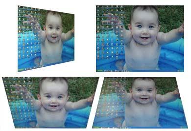
A visual comparison of the influence of viewing angles (photos taken at an angle of 50°) on image characteristics of monitors with different types of matrices:

Indicative table of comparative user characteristics depending on the type of matrix used:
Creating an LCD Display
The first working liquid crystal display was created by Fergason in 1970. Previously, LCD devices consumed too much power, had a limited lifespan, and had poor image contrast. The new LCD display was introduced to the public in 1971 and then it received warm approval. Liquid crystals are organic substances that can change the amount of light transmitted under voltage. A liquid crystal monitor consists of two glass or plastic plates with a suspension between them. The crystals in this suspension are arranged parallel to each other, thereby allowing light to penetrate the panel. When an electric current is applied, the arrangement of the crystals changes and they begin to block the passage of light. LCD technology has become widespread in computers and projection equipment. The first liquid crystals were characterized by their instability and were not suitable for mass production. The real development of LCD technology began with the invention by English scientists of a stable liquid crystal - biphenyl. The first generation of liquid crystal displays can be seen in calculators, electronic games and watches. Modern LCD monitors are also called flat panels, active matrix dual scanning, thin film transistors. The idea of LCD monitors has been in the air for more than 30 years, but the research carried out did not lead to acceptable results, so LCD monitors did not gain a reputation for providing good image quality. Now they are becoming popular - everyone likes their elegant appearance, slim figure, compactness, efficiency (15-30 watts), in addition, it is believed that only wealthy and serious people can afford such luxury
Characteristics of LCD monitors
Types of LCD monitors

Monitor Composite Layers
There are two types of LCD monitors: DSTN (dual-scan twisted nematic) and TFT (thin film transistor), also called passive and active matrices, respectively. Such monitors consist of the following layers: a polarizing filter, a glass layer, an electrode, a control layer, liquid crystals, another control layer, an electrode, a glass layer and a polarizing filter. The first computers used eight-inch (diagonally) passive black-and-white matrices. With the transition to active matrix technology, the screen size has increased. Almost all modern LCD monitors use thin-film transistor panels, which provide bright, clear images of a much larger size.
Monitor resolution
The size of the monitor determines the workspace it occupies and, importantly, its price. Despite the established classification of LCD monitors depending on the diagonal size of the screen (15-, 17-, 19-inch), a more correct classification is by operating resolution. The fact is that, unlike CRT-based monitors, the resolution of which can be changed quite flexibly, LCD displays have a fixed set of physical pixels. That is why they are designed to work with only one resolution, called working. Indirectly, this resolution also determines the diagonal size of the matrix, however, monitors with the same operating resolution may have different matrix sizes. For example, 15- to 16-inch monitors generally have a working resolution of 1024 x 768, which means that a given monitor actually physically contains 1024 horizontal pixels and 768 vertical pixels. The operating resolution of the monitor determines the size of the icons and fonts that will be displayed on the screen. For example, a 15-inch monitor can have a working resolution of both 1024 x 768 and 1400 x 1050 pixels. In the latter case, the physical dimensions of the pixels themselves will be smaller, and since the same number of pixels is used when forming a standard icon in both cases, then at a resolution of 1400×1050 pixels the icon will be smaller in its physical dimensions. For some users, too small icon sizes with a high monitor resolution may be unacceptable, so when purchasing a monitor you should immediately pay attention to the working resolution. Of course, the monitor is capable of displaying images in a different resolution than the working one. This mode of monitor operation is called interpolation. In the case of interpolation, the image quality leaves much to be desired. The interpolation mode significantly affects the quality of display of screen fonts.
Monitor interface
LCD monitors by their nature are digital devices, so the “native” interface for them is the DVI digital interface, which can have two types of convectors: DVI-I, which combines digital and analog signals, and DVI-D, which transmits only a digital signal. It is believed that the DVI interface is more preferable for connecting an LCD monitor to a computer, although connection via a standard D-Sub connector is also allowed. The DVI interface is also supported by the fact that in the case of an analog interface, double conversion of the video signal occurs: first, the digital signal is converted to analog in the video card (DAC conversion), which is then transformed into a digital signal by the electronic unit of the LCD monitor itself (ADC conversion), As a result, the risk of various signal distortions increases. Many modern LCD monitors have both D-Sub and DVI connectors, which allows you to simultaneously connect two system units to the monitor. You can also find models that have two digital connectors. Inexpensive office models mostly have only a standard D-Sub connector.
LCD matrix type
The basic component of the LCD matrix is liquid crystals. There are three main types of liquid crystals: smectic, nematic and cholesteric. According to their electrical properties, all liquid crystals are divided into two main groups: the first includes liquid crystals with positive dielectric anisotropy, the second - with negative dielectric anisotropy. The difference lies in how these molecules react to an external electric field. Molecules with positive dielectric anisotropy are oriented along the field lines, and molecules with negative dielectric anisotropy are oriented perpendicular to the field lines. Nematic liquid crystals have positive dielectric anisotropy, while smectic liquid crystals, on the contrary, have negative dielectric anisotropy. Another remarkable property of LC molecules is their optical anisotropy. In particular, if the orientation of the molecules coincides with the direction of propagation of plane-polarized light, then the molecules do not have any effect on the plane of polarization of the light. If the orientation of the molecules is perpendicular to the direction of propagation of light, then the plane of polarization is rotated so as to be parallel to the direction of orientation of the molecules. The dielectric and optical anisotropy of LC molecules makes it possible to use them as a kind of light modulators, allowing the formation of the desired image on the screen. The principle of operation of such a modulator is quite simple and is based on changing the plane of polarization of light passing through the LCD cell. The LCD cell is located between two polarizers, the polarization axes of which are mutually perpendicular. The first polarizer cuts out plane-polarized radiation from the light passing from the backlight lamp. If there were no LC cell, then such plane-polarized light would be completely absorbed by the second polarizer. An LCD cell placed in the path of transmitted plane-polarized light can rotate the plane of polarization of the transmitted light. In this case, part of the light passes through the second polarizer, that is, the cell becomes transparent (fully or partially). Depending on how the rotation of the polarization plane in the LC cell is controlled, several types of LC matrices are distinguished. So, an LCD cell placed between two crossed polarizers allows the transmitted radiation to be modulated, creating gradations of black and white color. To obtain a color image, it is necessary to use three color filters: red (R), green (G) and blue (B), which, when installed in the path of white light, will allow you to obtain three basic colors in the required proportions. So, each pixel of an LCD monitor consists of three separate sub-pixels: red, green and blue, which are controlled LCD cells and differ only in the filters used, installed between the top glass plate and the output polarizing filter
Classification of TFT-LCD displays
The main technologies in the manufacture of LCD displays: TN+film, IPS (SFT) and MVA. These technologies differ in the geometry of the surfaces, polymer, control plate and front electrode. The purity and type of polymer with liquid crystal properties used in specific developments are of great importance.
TN matrix

TN cell structure
A TN-type (Twisted Nematic) liquid crystal matrix is a multilayer structure consisting of two polarizing filters, two transparent electrodes and two glass plates, between which the actual nematic liquid crystal substance with positive dielectric anisotropy is located. Special grooves are applied to the surface of the glass plates, which makes it possible to create an initially identical orientation of all liquid crystal molecules along the plate. The grooves on both plates are mutually perpendicular, so the layer of liquid crystal molecules between the plates changes its orientation by 90°. It turns out that LC molecules form a spirally twisted structure (Fig. 3), which is why such matrices are called Twisted Nematic. Glass plates with grooves are located between two polarizing filters, and the polarization axis in each filter coincides with the direction of the grooves on the plate. In its normal state, an LCD cell is open because the liquid crystals rotate the plane of polarization of light passing through them. Therefore, plane-polarized radiation generated after passing through the first polarizer will also pass through the second polarizer, since its polarization axis will be parallel to the polarization direction of the incident radiation. Under the influence of the electric field created by transparent electrodes, the molecules of the liquid crystal layer change their spatial orientation, lining up along the direction of the field lines. In this case, the liquid crystal layer loses the ability to rotate the plane of polarization of the incident light, and the system becomes optically opaque, since all the light is absorbed by the output polarizing filter. Depending on the applied voltage between the control electrodes, it is possible to change the orientation of the molecules along the field not completely, but only partially, that is, to regulate the degree of twisting of the LC molecules. This, in turn, allows you to change the intensity of the light passing through the LCD cell. Thus, by installing a backlight lamp behind the LCD matrix and changing the voltage between the electrodes, you can vary the degree of transparency of one LCD cell. TN matrices are the most common and cheapest. They have certain disadvantages: not very large viewing angles, low contrast and the inability to get perfect black color. The fact is that even when the maximum voltage is applied to the cell, it is impossible to completely spin the LC molecules and orient them along the field lines. Therefore, such matrices remain slightly transparent even when the pixel is completely turned off. The second drawback is related to small viewing angles. To partially eliminate it, a special scattering film is applied to the surface of the monitor, which allows you to increase the viewing angle. This technology is called TN+Film, which indicates the presence of this film. Finding out exactly what type of matrix is used in the monitor is not so easy. However, if there is a “broken” pixel on the monitor resulting from the failure of the transistor that controls the LCD cell, then in TN matrices it will always light up brightly (red, green or blue), since for a TN matrix an open pixel corresponds to a lack of voltage on the cell. You can recognize a TN matrix by looking at the black color at maximum brightness - if it is more gray than black, then it is probably a TN matrix.
IPS matrices

IPS cell structure
Monitors with an IPS matrix are also called Super TFT monitors. A distinctive feature of IPS matrices is that the control electrodes are located in the same plane on the bottom side of the LCD cell. In the absence of voltage between the electrodes, the LC molecules are located parallel to each other, the electrodes, and the polarization direction of the lower polarizing filter. In this state, they do not affect the polarization angle of the transmitted light, and the light is completely absorbed by the output polarizing filter, since the polarization directions of the filters are perpendicular to each other. When voltage is applied to the control electrodes, the generated electric field rotates the LC molecules by 90° so that they are oriented along the field lines. If light is passed through such a cell, then due to the rotation of the polarization plane, the upper polarizing filter will transmit light without interference, that is, the cell will be in the open state (Fig. 4). By varying the voltage between the electrodes, it is possible to force the LC molecules to rotate at any angle, thereby changing the transparency of the cell. In all other respects, IPS cells are similar to TN matrices: a color image is also formed through the use of three color filters. IPS matrices have both advantages and disadvantages compared to TN matrices. The advantage is the fact that in this case the color is perfectly black, and not gray, as in TN matrices. Another undeniable advantage of this technology is the large viewing angles. The disadvantages of IPS matrices include a longer pixel response time than for TN matrices. However, we will return to the issue of pixel reaction time later. In conclusion, we note that there are various modifications of IPS matrices (Super IPS, Dual Domain IPS) that can improve their characteristics.
MVA matrices
Domain structure of an MVA cell
MVA is a development of VA technology, that is, technology with vertical molecular ordering. Unlike TN and IPS matrices, in this case liquid crystals with negative dielectric anisotropy are used, which are oriented perpendicular to the direction of the electric field lines. In the absence of voltage between the plates of the LC cell, all liquid crystal molecules are oriented vertically and have no effect on the plane of polarization of transmitted light. Since the light passes through two crossed polarizers, it is completely absorbed by the second polarizer and the cell is in a closed state, while, unlike the TN matrix, it is possible to obtain a perfectly black color. When a voltage is applied to the electrodes located above and below, the molecules rotate 90°, orienting themselves perpendicular to the electric field lines. When plane-polarized light passes through such a structure, the plane of polarization rotates by 90° and the light passes freely through the output polarizer, that is, the LC cell is in the open state. The advantages of systems with vertical ordering of molecules are the ability to obtain ideal black color (which, in turn, affects the ability to obtain high-contrast images) and short pixel response time. In order to increase viewing angles, systems with vertical ordering of molecules use a multidomain structure, which leads to the creation of MVA-type matrices. The idea behind this technology is that each subpixel is divided into several zones (domains) using special protrusions, which slightly change the orientation of the molecules, forcing them to align with the surface of the protrusion. This leads to the fact that each such domain shines in its own direction (within a certain solid angle), and the totality of all directions expands the viewing angle of the monitor. The advantages of MVA matrices include high contrast (due to the ability to obtain perfectly black color) and large viewing angles (up to 170°). Currently, there are several varieties of MVA technology, for example PVA (Patterned Vertical Alignment) from Samsung, MVA-Premium, etc., which further enhance the characteristics of MVA matrices.
Brightness
Today, in LCD monitors, the maximum brightness stated in the technical documentation ranges from 250 to 500 cd/m2. And if the brightness of the monitor is high enough, then this is necessarily indicated in advertising brochures and presented as one of the main advantages of the monitor. However, this is precisely where one of the pitfalls lies. The paradox is that it is impossible to rely on the numbers indicated in the technical documentation. This applies not only to brightness, but also to contrast, viewing angles and pixel response time. Not only may they not correspond to actual observed values at all, but sometimes it is even difficult to understand what these numbers mean. First of all, there are different measurement techniques described in different standards; Accordingly, measurements carried out using different methods give different results, and you are unlikely to be able to find out exactly what method and how the measurements were carried out. Here's one simple example. The measured brightness depends on the color temperature, but when they say that the monitor brightness is 300 cd/m2, the question arises: at what color temperature is this maximum brightness achieved? Moreover, manufacturers indicate brightness not for the monitor, but for the LCD matrix, which is not at all the same thing. To measure brightness, special reference generator signals with a precisely specified color temperature are used, so the characteristics of the monitor itself as a final product may differ significantly from those stated in the technical documentation. But for the user, the characteristics of the monitor itself, and not the matrix, are of paramount importance. Brightness is a really important characteristic for an LCD monitor. For example, if the brightness is insufficient, you are unlikely to be able to play various games or watch DVD movies. In addition, it will be uncomfortable to work at the monitor in daylight conditions (external illumination). However, it would be premature to conclude on this basis that a monitor with a declared brightness of 450 cd/m2 is somehow better than a monitor with a brightness of 350 cd/m2. Firstly, as already noted, declared and real brightness are not the same thing, and secondly, it is quite enough for the LCD monitor to have a brightness of 200-250 cd/m2 (not declared, but actually observed). In addition, the way in which the brightness of the monitor is adjusted is also important. From a physics point of view, brightness adjustment can be done by changing the brightness of the backlight. This is achieved either by adjusting the discharge current in the lamp (in monitors, Cold Cathode Fluorescent Lamps, CCFLs are used as backlights), or by so-called pulse-width modulation of the lamp power supply. With pulse-width modulation, voltage is supplied to the backlight lamp in pulses of a certain duration. As a result, the backlight lamp does not glow constantly, but only at periodically repeating time intervals, but due to the inertia of vision, it seems that the lamp is constantly on (the pulse repetition rate is more than 200 Hz). Obviously, by changing the width of the supplied voltage pulses, you can adjust the average brightness of the backlight. In addition to adjusting the brightness of the monitor using the backlight, sometimes this adjustment is carried out by the matrix itself. In fact, a DC component is added to the control voltage at the electrodes of the LCD cell. This allows the LCD cell to be fully opened, but does not allow it to be completely closed. In this case, as the brightness increases, the black color ceases to be black (the matrix becomes partially transparent even when the LCD cell is closed).
Contrast
An equally important characteristic of an LCD monitor is its contrast, which is defined as the ratio of the brightness of the white background to the brightness of the black background. Theoretically, the contrast of the monitor should not depend on the brightness level set on the monitor, that is, at any brightness level, the measured contrast should have the same value. Indeed, the brightness of the white background is proportional to the brightness of the backlight. Ideally, the ratio of the light transmittance of an LCD cell in the open and closed state is a characteristic of the LCD cell itself, but in practice this ratio may depend on both the set color temperature and the set brightness level of the monitor. Recently, the image contrast on digital monitors has increased significantly, and now this figure often reaches 500:1. But here everything is not so simple. The fact is that contrast can be specified not for the monitor, but for the matrix. However, as experience shows, if the passport indicates a contrast of more than 350:1, then this is quite enough for normal operation.
Viewing angle
The maximum viewing angle (both vertical and horizontal) is defined as the angle from which the image contrast in the center is at least 10:1. Some matrix manufacturers, when determining viewing angles, use a contrast ratio of 5:1 rather than 10:1, which also introduces some confusion into the technical specifications. The formal definition of viewing angles is quite vague and, most importantly, has no direct bearing on the correct color rendering when viewing an image at an angle. In fact, for users, a much more important circumstance is the fact that when viewing an image at an angle to the surface of the monitor, it is not a drop in contrast that occurs, but color distortions. For example, red turns into yellow, and green turns into blue. Moreover, such distortions manifest themselves differently in different models: in some they become noticeable even at a slight angle, much smaller than the viewing angle. Therefore, it is fundamentally wrong to compare monitors based on viewing angles. It is possible to compare, but such a comparison has no practical significance.
Pixel response time

Typical pixel turn-on timing diagram for a TN+Film matrix

Typical pixel turn-off timing diagram for a TN+Film matrix
Reaction time, or pixel response time, is usually indicated in the technical documentation for the monitor and is considered one of the most important characteristics of the monitor (which is not entirely true). In LCD monitors, the pixel response time, which depends on the type of matrix, is measured in tens of milliseconds (in new TN+Film matrices, the pixel response time is 12 ms), and this leads to blurring of the changing picture and can be noticeable to the eye. A distinction is made between pixel on and off time. The pixel on time refers to the period of time required to open the LCD cell, and the off time refers to the period of time required to close it. When we talk about the reaction time of a pixel, we mean the total time the pixel turns on and off. The time a pixel turns on and the time it turns off can vary significantly. When they talk about the pixel response time indicated in the technical documentation for the monitor, they mean the response time of the matrix, not the monitor. In addition, the pixel response time indicated in the technical documentation is interpreted differently by different matrix manufacturers. For example, one of the options for interpreting the time to turn a pixel on (off) is that this is the time the pixel brightness changes from 10 to 90% (from 90 to 10%). Until now, when talking about measuring pixel response time, it is assumed that we are talking about switching between black and white colors. If there are no issues with black (the pixel is simply closed), then the choice of white is not obvious. How will a pixel's response time change if measured as it switches between different halftones? This question is of great practical importance. The fact is that switching from a black background to a white one, or vice versa, is relatively rare in real applications. In most applications, transitions between halftones are usually implemented. And if the switching time between black and white colors turns out to be less than the switching time between grayscale, then the pixel response time will not have any practical significance and you cannot rely on this characteristic of the monitor. What conclusion can be drawn from the above? Everything is very simple: the pixel response time declared by the manufacturer does not allow us to clearly judge the dynamic characteristics of the monitor. In this sense, it is more correct to speak not about the time a pixel switches between white and black colors, but about the average time a pixel switches between halftones.
Number of colors displayed
All monitors by their nature are RGB devices, that is, the color in them is obtained by mixing in various proportions the three basic colors: red, green and blue. Thus, each LCD pixel consists of three color subpixels. In addition to the completely closed or completely open state of the LCD cell, intermediate states are also possible when the LCD cell is partially open. This allows you to form a color shade and mix the color shades of the base colors in the desired proportions. In this case, the number of colors reproduced by the monitor theoretically depends on how many color shades can be formed in each color channel. Partial opening of the LCD cell is achieved by applying the required voltage level to the control electrodes. Therefore, the number of reproducible color shades in each color channel depends on how many different voltage levels can be applied to the LCD cell. To generate an arbitrary voltage level, you will need to use DAC circuits with a large bit capacity, which is extremely expensive. Therefore, modern LCD monitors most often use 18-bit DACs and less often - 24-bit ones. When using an 18-bit DAC, there are 6 bits per color channel. This allows you to generate 64 (26=64) different voltage levels and, accordingly, obtain 64 color shades in one color channel. In total, by mixing color shades of different channels, it is possible to create 262,144 color shades. When using a 24-bit matrix (24-bit DAC circuit), each channel has 8 bits, which makes it possible to generate 256 (28=256) color shades in each channel, and in total such a matrix reproduces 16,777,216 color shades. At the same time, for many 18-bit matrices the data sheet indicates that they reproduce 16.2 million color shades. What is the matter here and is this possible? It turns out that in 18-bit matrices, through all sorts of tricks, you can bring the number of color shades closer to what is reproduced by real 24-bit matrices. To extrapolate color tones in 18-bit matrices, two technologies (and combinations thereof) are used: dithering and FRC (Frame Rate Control). The essence of dithering technology is that the missing color shades are obtained by mixing the closest color shades of neighboring pixels. Let's look at a simple example. Let's assume that a pixel can only be in two states: open and closed, with the closed state of the pixel producing black, and the open state producing red. If instead of one pixel we consider a group of two pixels, then, in addition to black and red, we can also obtain an intermediate color, thereby extrapolating from a two-color mode to a three-color one. As a result, if initially such a monitor could generate six colors (two for each channel), then after such dithering it will already reproduce 27 colors. The dithering scheme has one significant drawback: an increase in color shades is achieved by reducing the resolution. In fact, this increases the pixel size, which can have a negative impact when drawing image details. The essence of FRC technology is to manipulate the brightness of individual subpixels by additionally turning them on/off. As in the previous example, a pixel is considered to be either black (off) or red (on). Each subpixel is commanded to turn on at a frame rate, that is, at a frame rate of 60 Hz, each subpixel is commanded to turn on 60 times per second. This allows the color red to be generated. If you force the pixel to turn on not 60 times per second, but only 50 (at every 12th clock cycle, turn the pixel off rather than turn it on), then the resulting brightness of the pixel will be 83% of the maximum, which will allow the formation of an intermediate color shade of red. Both color extrapolation methods discussed have their drawbacks. In the first case, there is a possible flickering of the screen and a slight increase in reaction time, and in the second, there is the possibility of loss of image details. It is quite difficult to distinguish an 18-bit matrix with color extrapolation from a true 24-bit matrix by eye. At the same time, the cost of a 24-bit matrix is much higher.
Operating principle of TFT-LCD displays
The general principle of image formation on the screen is well illustrated in Fig. 1. But how to control the brightness of individual subpixels? It is usually explained to beginners this way: behind each subpixel there is a liquid crystal shutter. Depending on the voltage applied to it, it transmits more or less light from the backlight. And everyone immediately imagines some kind of dampers on small hinges that rotate to the desired angle... something like this:
In reality, of course, everything is much more complicated. There are no material flaps on the hinges. In a real liquid crystal matrix, the luminous flux is controlled something like this:
The light from the backlight (we follow the picture from bottom to top) first passes through the lower polarizing filter (white shaded plate). Now this is no longer an ordinary stream of light, but a polarized one. Then the light passes through translucent control electrodes (yellow plates) and encounters a layer of liquid crystals on its way. By changing the control voltage, the polarization of the light flux can be changed by up to 90 degrees (in the picture on the left), or left unchanged (right there). Attention, the fun is about to begin! After the layer of liquid crystals, light filters are located and here each subpixel is colored in the desired color - red, green or blue. If we look at the screen with the top polarizing filter removed, we will see millions of glowing subpixels - and each one glows with maximum brightness, because our eyes cannot distinguish the polarization of light. In other words, without the top polarizer we will simply see a uniform white glow over the entire surface of the screen. But as soon as you put the upper polarizing filter in place, it will “reveal” all the changes that liquid crystals have made to the polarization of light. Some subpixels will remain brightly glowing, like the left one in the figure, whose polarization was changed by 90 degrees, and some will go out, because the upper polarizer is in antiphase to the lower one and does not transmit light with the default polarization. There are also subpixels with intermediate brightness - the polarization of the light flow passing through them was rotated not by 90, but by a smaller number of degrees, for example, by 30 or 55 degrees.
Advantages and disadvantages
|
Symbols: (+) advantage, (~) acceptable, (-) disadvantage |
||
| LCD monitors
| CRT monitors
|
|
| Brightness | (+) from 170 to 250 cd/m2 | (~) from 80 to 120 cd/m2 |
| Contrast | (~) 200:1 to 400:1 | (+) from 350:1 to 700:1 |
| Viewing angle (by contrast) | (~) 110 to 170 degrees | (+) over 150 degrees |
| Viewing angle (by color) | (-) from 50 to 125 degrees | (~) over 120 degrees |
| Permission | (-) Single resolution with fixed pixel size. Optimally can only be used in this resolution; Depending on the supported expansion or compression functions, higher or lower resolutions can be used, but they are not optimal. | (+) Various resolutions are supported. With all supported resolutions, the monitor can be used optimally. The limitation is imposed only by the acceptability of the regeneration frequency. |
| Vertical frequency | (+) Optimal frequency 60 Hz, which is enough to avoid flickering | (~) Only at frequencies above 75 Hz there is no clearly noticeable flicker |
| Color registration errors | (+) no | (~) 0.0079 to 0.0118 inches (0.20 - 0.30 mm) |
| Focusing | (+) very good | (~) from satisfactory to very good> |
| Geometric/linear distortion | (+) no | (~) possible |
| Broken pixels | (-) up to 8 | (+) no |
| Input signal | (+) analog or digital | (~) analog only |
| Scaling at different resolutions | (-) is absent or interpolation methods that do not require large overheads are used | (+) very good |
| Color Accuracy | (~) True Color is supported and the required color temperature is simulated | (+) True Color is supported and there are a lot of color calibration devices on the market, which is a definite plus |
| Gamma correction (color adjustment to the characteristics of human vision) | (~) satisfactory | (+) photorealistic |
| Uniformity | (~) often the image is brighter at the edges | (~) often the image is brighter in the center |
| Color purity/color quality | (~) good | (+) high |
| Flicker | (+) no | (~) not noticeable above 85 Hz |
| Inertia time | (-) from 20 to 30 ms. | (+) negligible |
| Image formation | (+) The image is formed by pixels, the number of which depends only on the specific resolution of the LCD panel. The pixel pitch depends only on the size of the pixels themselves, but not on the distance between them. Each pixel is individually shaped for superior focus, clarity and clarity. The image is more complete and smooth | (~) Pixels are formed by a group of dots (triads) or stripes. The pitch of a point or line depends on the distance between points or lines of the same color. As a result, the sharpness and clarity of the image is highly dependent on the size of the dot pitch or line pitch and on the quality of the CRT |
| Energy consumption and emissions | (+) There are practically no dangerous electromagnetic radiations. Power consumption is approximately 70% lower than standard CRT monitors (25 to 40 W). | (-) Electromagnetic radiation is always present, but the level depends on whether the CRT meets any safety standard. Energy consumption in operating condition is 60 - 150 W. |
| Dimensions/weight | (+) flat design, light weight | (-) heavy design, takes up a lot of space |
| Monitor interface | (+) Digital interface, however, most LCD monitors have a built-in analog interface for connecting to the most common analog outputs of video adapters | (-) Analog interface |


Literature
- A.V.Petrochenkov “Hardware-computer and peripherals”, -106 page ill.
- V.E. Figurnov “IBM PC for the user”, -67 pages.
- “HARD "n" SOFT" (computer magazine for a wide range of users) No. 6 2003.
- N.I. Gurin “Working on a personal computer,” - 128 pages.


