It's a contact ignition system. Contact ignition systems, device, principle of operation. Malfunctions and their causes
To create a spark discharge between the electrodes of the spark plug, a high voltage (15000-30000 V) is required, since the gases in the cylinder do not conduct low voltage current. Used on modern car engines single-wire system for connecting current sources with consumers. The second conductor of electrical energy is weight (body) - all the interconnected metal parts of the car.
With a single-wire system for switching on electrical equipment, the number of wires is reduced, maintenance is simplified and the cost of the system is reduced. The negative terminals of the generator, battery and all electrical consumers are connected to ground, and the positive terminals are isolated from it. During operation, it is necessary to carefully monitor the condition of the insulation on the wires and their fastening, since a violation of the insulation can lead to short circuit .
:
Diagram of the contact system of battery ignition :
a) diagram; b) position of the ignition switch and starter key; 1 - breaker lever; 2 - moving contact; 3 - fixed contact; 4 - cam; 5 - low voltage breaker; 6 - capacitor; 7, 14, 23 - wires; 8 - ignition switch; 9 - additional resistor; 10 - primary winding; 11 - secondary winding; 12 - ignition coil; 13 - magnetic circuit; 15 - additional resistor switch; 16 - ammeter; 17 - battery; 18 - electrode switch; 19 - rotor with electrode; 20 - distributor; 21, 24 - suppression resistors; 25 - spark plug; 26 - ignition switch key.
Contact battery ignition system comprises : battery 17, ignition coil 12, low voltage breaker 5 with capacitor 6, high voltage pulse distributor 20, spark plugs 25, ignition switch 8, ammeter 16. Breaker 5 has two contacts: fixed 3 connected to ground and movable 2 located on lever 1 and connected to wire 7 with the primary winding 10 of the ignition coil. The breaker contains a rotating roller with a cam 4, with the help of which the contacts are opened. The ignition system uses an alternating current generator as a source of electric current.
When the breaker contacts close, the current from the battery passes through the primary winding of the ignition coil, creating a magnetic field around it.
The low voltage circuit is as follows : positive battery terminal 17 - ammeter 16 - ignition switch 8 additional resistor 9 - primary winding 10 - wire 7 - moving contact 2 - fixed contact 3 - ground - battery circuit switch 18 - negative battery terminal.
When the breaker contacts open, the primary winding of the ignition coil is de-energized and the magnetic field sharply decreases. The magnetic flux of the vanishing field crosses the turns of the secondary and primary windings, while a high-voltage electromotive force (EMF) is induced in the secondary and self-induction EMF in the primary windings. High voltage pulses arising in the secondary winding are supplied to the spark plugs in accordance with the operating order of the engine cylinders. The rotating rotor 19, with its electrode, distributes high voltage pulses across the electrodes of the distributor cap. The rotor speed is 2 times less than the crankshaft speed and thus coincides with the speed of the chopper cam.
The position of the rotor plate opposite each of the electrodes of the distributor cap corresponds to the open state of the breaker contacts.
High voltage circuit : secondary winding 11 - high voltage wire 14 - suppressive resistor 21 - rotor electrode 19 - one of the electrodes of the distributor cap 20 - wire 23 - suppressive resistor 24 - spark plug 25 - central electrode of the spark plug - side electrode of the spark plug - ground - battery circuit switch 18 - negative battery terminal 17 - positive battery terminal 17 - ammeter 16 - ignition switch 8 - additional resistor 9 - primary winding 10 - secondary winding of the ignition coil 12.
In the primary winding, a self-induction current occurs when the breaker contacts close. The self-induction current slows down the process of disappearance of the current in the primary winding, which is undesirable, since when the contacts open, the spark formation period between them increases, and the efficiency and reliability of the ignition system decreases. Capacitor 6 is connected parallel to the contacts of the breaker. At the moment the low voltage circuit opens, the capacitor is charged by self-induction current, and then, when the contacts are open, it is discharged through the primary winding.
Ignition switch 8 is necessary to stop a running engine by opening the primary winding of the ignition coil. It is also needed to turn on the ignition before starting the engine. The ignition switch key 26 can have four positions: 0 - ignition off; 1 - ignition on; 2 - ignition and starter are on; 3 - Power is supplied to the radio. In position 0, the key can be inserted and removed from the ignition switch. After starting the engine, the ignition switch key is turned to position 1.
Switch 18 of the battery circuit is needed to disconnect the battery from ground when performing electrical work and to stop the car for a long time. Switch 18 protects electrical equipment from short circuits or fire due to faulty wiring, and also allows you to disconnect the battery from all consumers of electrical energy without directly disconnecting the wires coming from it. In this case, the emergency lighting remains on - the cabin lamp and the portable lamp socket.
Why is the contact battery ignition system not used on modern cars?
Gradually, the contact battery ignition system was replaced by other systems, such as contact transistor or contactless ignition systems. This was preceded a number of disadvantages of the contact battery ignition system :
- Rapid wear and burning of breaker contacts;
- Increasing the gap between the contacts of the breaker, accordingly increasing the ignition timing;
- Reducing current in low and high voltage circuits;
- Frequent interruptions in ignition of the working mixture;
- Difficulty starting the engine;
- Reduced engine efficiency and power.
The ignition system of any car is needed to generate high currents and transfer them to the spark plugs, which directly ignite the fuel mixture. The importance of its precise functioning and settings cannot be overestimated, because any malfunctions will make the operation of the car impossible. Voltage to the spark plugs is not supplied randomly, but taking into account the current crankshaft speed and the degree of load on the engine. The contact ignition system is gradually becoming a thing of the past, giving way to more advanced developments.
How does this system work?
A standard battery and generator are used as a source of electricity necessary to generate high-voltage pulses in a car. But they are only a source of low-voltage currents that cannot directly ignite the mixture. To form a good spark in a candle, it needs a voltage of up to 20 thousand volts. Therefore, any contact-transistor ignition system consists of many elements:

Ignition coil
It is required to convert low-voltage currents coming from the battery into high-voltage ones, and is located in the engine compartment. The operating principle of this element is quite simple. A low-voltage current passing through the turns of the winding promotes the formation of a magnetic field directly near the winding. When the power supply is interrupted, high-voltage currents are excited in the high-voltage turns due to the disappeared magnetic field and the difference in turns in the windings themselves. When applied to the spark plugs, such current can cause the formation of a stable spark.
Breaker
Designed to interrupt currents in low-voltage windings, it plays an important role in the generation of high-voltage pulses, since it is at the moment of interrupting low currents that a high voltage is generated and supplied to the main contact. It is equipped with a spring, which ensures its constant tight connection to the fixed part. The divergence of contacts occurs for a short period of time.
Capacitor
The circuit of the contact ignition system includes a capacitor, the presence of which eliminates the possibility of the contacts burning at the moment when they open and sparks form. The capacitor is able not only to absorb the bulk of the energy and minimize sparking, but also to help increase the voltage in the windings. When the contacts in the breaker are triggered, it releases the existing current, which leads to the formation of reverse currents and the rapid disappearance of the resulting magnetic field. This process directly affects the strength of the current generated.
Distributor
This unit distributes the generated high voltage to the spark plugs themselves, in which sparking begins. For transmission, armored wires are used to connect the spark plugs to the lid, and all contacts are numbered, and each of them is intended for a strictly specific cylinder. The voltage is not supplied randomly, but at a strictly defined moment - at the very end of the compression stroke. Correct ignition of the mixture will occur only when the advance angle is set correctly - for a contact ignition system this is a very important point.

Centrifugal and vacuum regulators
The centrifugal type regulator plays an important role in setting the correct advance angle depending on the current crankshaft speed. The vacuum is also designed to adjust spark formation in accordance with the current operating mode of the engine, and is located on the distributor cover. It has two chambers, one of which is open to the atmosphere, the other is hermetically connected to the throttle tank. The rod on the diaphragm is connected to a plate located on the contacts of the breaker.
Candles
An integral part of the contact ignition system is designed to directly ignite the mixture in the cylinders. A spark breakdown occurs in them at the moment a high voltage is applied, and with sufficient current and the correct gap between the contacts of the spark plug, the spark is able to instantly ignite the mixture. How this whole system works is shown in the video:
Possible problems during operation
The most common problem with a contact ignition system is the lack of sparking. Among the main reasons for this are the following:

In addition, the problem can also be caused by a capacitor, coil or armor wires. Often problems with starting the engine are caused by the spark plugs themselves, on which the gap is set incorrectly. To independently fix problems with the contact ignition system, you need to thoroughly check all elements using a multimeter. A lot of attention will have to be paid to all existing contacts - their oxidation is one of the most common causes of incorrect operation of the ignition system.
The majority of “classic” VAZ 2101, 2102, 2103, 2104, 2105, 2106, 2107, 2121 cars have a contact ignition system. Contact - since its operation is based on opening the contacts of the breaker in the distributor. Knowing its principle of operation and operating procedure, you can quickly and effectively eliminate many problems in the operation of the car engine and the system itself.
A little about the design of the contact ignition system of VAZ 2101, 2102, 2103, 2104, 2105, 2106, 2107, 2121 cars
The contact system of the cars listed above has two electrical circuits: low and high voltage (primary and secondary circuits). The low voltage circuit is:
battery -
— output “30” of the generator —
- fuse and relay mounting block -
- egnition lock -
— primary winding of the ignition coil (terminal “B”) —
— breaker output in the distributor (contacts).
On VAZ 2101, 2102, 2103, 2106, 2121 vehicles, the mounting block is not included in the low voltage circuit.
High voltage circuit:
Secondary winding of the ignition coil -
— central high-voltage wire from the ignition coil to the distributor cover —
— ignition distributor —
— high-voltage wires to the spark plugs —
- spark plug.
Where does the electric current come from in the contact ignition system?
Electric current enters the ignition system from the battery through the primary circuit or, when the voltage supplied by the generator becomes higher than the battery voltage, then from terminal “30” of the generator also through the primary circuit.
Operating principle of the contact ignition system
Electric current flowing through the primary winding of the ignition coil creates a strong magnetic field around its turns. When the contacts of the breaker open under the action of the tetrahedral cam on the distributor shaft, the current in the primary winding disappears. The magnetic force field is sharply reduced and, crossing the turns of the primary and secondary windings of the ignition coil, induces an EMF in them, proportional to the number of turns. The EMF in the secondary winding of the coil reaches a value of 12000 - 24000 V.
Through a secondary circuit, this high voltage electrical current is supplied to the spark plugs, creating a spark between their contacts, thereby igniting the fuel mixture.
Schemes of contact ignition systems
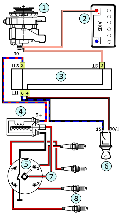 diagram of the contact ignition system for VAZ 2105, 2107 cars
 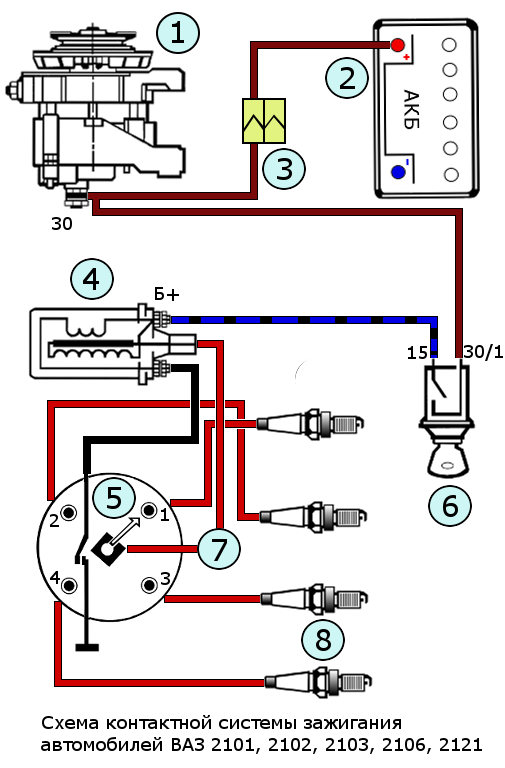 diagram of the contact ignition system for VAZ 2101, 2102, 2103, 2106, 2121 cars
 Notes and additions
— EMF (electromotive force) is a physical quantity characterizing the action of external forces in a current source, measured in volts. It appears in current sources when a change occurs in the magnetic field.
The engine ignition system is needed to reproduce high currents and distribute them to the contact spark plugs of the fuel. Taking into account changes in crankshaft speed and engine loads, a high-voltage voltage pulse is supplied to the spark plugs at a given period. Nowadays, cars are equipped with contact and non-contact ignition timing systems.
Contact ignition system device
Low-voltage currents serve as a power source and come from the generator and vehicle battery.
As a rule, the value of this voltage is twelve to fourteen volts. And to reproduce the moment of spark in the fuse candles, you need to apply up to twenty thousand volts to them. Taking this factor into account, the ignition system has two different electrical circuits in its design. The ignition system circuit is assembled from the following devices and elements: battery, coil, distributor, ignition timing regulators of vacuum and centrifugal types, spark plugs, electrical wires, switching lock device.
Individual elements of the system
To convert low-voltage currents into high ones, the design provides for the installation of an ignition coil device. It is located in the engine compartment, like most of the elements and ignition mechanisms. The main method of operation is as follows: electric currents pass through the turns of a low-voltage winding, and at this moment a magnetic field is transformed near the winding. If you stop supplying voltage to the turns, the disappeared magnetic field excites currents directly in the high-voltage turns. The process of converting twelve volts into twenty thousand occurs due to the difference in turns in the windings of the coils. It is precisely this high voltage that is necessary to form a spark between the contacts of the spark plugs.
Breaker operation
Correct operation of the ignition system is impossible without a mechanism such as a low current voltage breaker. Its job is to interrupt currents in low voltage windings. This, in turn, contributes to the formation of high voltage.

Next, the current is directed to the main contact located under the cover of the distributor device. The flexible spring of the movable contact constantly presses it against the stationary element, and they diverge only for a short period of time. This occurs at the moment when the cam of the drive roller of the breaker mechanism acts on the hammer of the movable contact.
Capacitor
To prevent the contacts from burning when they open, a capacitor is connected to them in parallel. During the period of divergence of contacts of the distributor mechanism between the cams, sparking is possible. In this case, the capacitor serves to absorb most of the electricity and reduce the possibility of sparking to a minimum. Additionally, it accompanies an increase in voltage in the secondary turns of the coil winding. At the moment the breaker contacts are triggered, the condensing device releases its current and thus creates reverse currents in the low voltage circuit. This helps accelerate the disappearance of magnetic fields. And the sooner this happens, the higher the currents in the high voltage line will be. In the event that the distributor capacitor fails, the motor will also not start and operate. The voltage parameters of the turns will be too low for optimal sparking to occur. The spark between the electrodes of the spark plug will be “poor”, and this is not enough to ignite the fuel mixture. The contacts of the low current breaker and the high voltage distributor are installed in the distributor housing and are driven by the engine crankshaft.
Distributor cover
The distribution of high voltage to the cylinder spark plugs of the power unit is carried out due to the distribution cover of the distributor. After high currents are generated in the coil, they are supplied to the main contact of the distributor-breaker cap, and only then, through the moving element, to the rotor plate. As the rotor rotates, voltage jumps from the plate to the contacts of the distribution cap.

Then short pulses are sent through high-voltage armored wires directly to the distribution cover contacts that have a specific numerology that corresponds to a specific engine cylinder.
This is how the timing of the cylinders is set. A certain operating procedure provides for uniform distribution of the load on the crankshaft. Basically, four-cylinder engines have the following operating order: 1-3-4-2. But it may vary slightly depending on the manufacturer. In this case, the operating order formula means that initially ignition occurs in the first cylinder, then in the third, fourth and second. In this case, the engine ignition system provides voltage to the spark plugs at the end of the compression stroke. This happens due to the installation
Advancing the moment of spark formation is necessary due to the high speed of movement of the pistons in the cylinders. In the case when the fuel mixture ignites slightly later or earlier than intended, the efficiency of the expanding gases will decrease significantly. Therefore, the fuel must be ignited at a given moment when the piston approaches TDC. With a correctly set advance angle, the piston will be exposed to the optimal amount of gases necessary for normal engine operation. The advance angle is set by rotating the breaker body. This is how a certain moment is selected when the breaker contacts are separated.
Centrifugal regulator
The centrifugal regulator ensures that the correct ignition timing is set depending on engine speed. The design of the regulator mechanism consists of a pair of weights that, rotating, act on the plate with the contacts of the breaker.
Vacuum regulator
Depending on the degree of load on the engine, the moment of spark formation is adjusted by a vacuum regulator. This device is mounted on the distributor body. The vacuum regulator consists of two chambers separated by a diaphragm. One chamber interacts with the atmosphere, and the second through a pipe with a throttle capacity. Using a rod, the diaphragm is connected to a plate, which is equipped with breaker contacts.
As the angle of rotation of the throttle valve increases, the vacuum in the throttle cavity decreases. In this case, the diaphragm moves the plate at a slight angle together with the contacts towards the breaker drive cam. Based on this, the opening occurs with a delay, and, accordingly, the angle changes.
Spark plugs (contact ignition system)
The ignition system is equipped with standard igniter elements. Spark contact elements are needed to convert electrical energy into a spark to ignite the fuel mixture in the engine cylinders. During the period when an electrical impulse is transmitted to the spark plugs, its contacts contribute to the formation of a spark breakdown. This part is an integral element of the ignition system.
Armored wires
The contact ignition system and other types of ignition systems are equipped with armored wires that can pass high-voltage voltage through them without damage or loss. In particular, it is an electrical flexible wire with one copper core and multilayer insulation.

In this case, the contact wire is made in the form of a spiral, which eliminates radio interference. As a rule, these wires are installed on spark plugs. With prolonged use, the insulation of the wires may develop microcracks, through which high-value pulses can be lost.
Ignition system malfunctions and their elimination
The first and most common failure may be the lack of spark at the spark plugs. The reasons for this malfunction may be the following:
- Breakage of electrical wires in a low voltage circuit or oxidation of their connecting contacts.
- Burning of distributor contacts and their misadjustment.
- Coil failure, capacitor burnout, distributor cap defects, damage to armored wires and the spark plugs themselves.
- Excessive moisture in devices.
Troubleshooting is possible using the following method:
- Checking the entire circuit and wiring with a tester.
- Cleaning the distributor contacts from carbon deposits and adjusting the gap.
- Replacement of faulty and suspicious system parts.
It happens that when the ignition key is turned, the starter does not operate, but all systems visually work; in this case, it is necessary to pay attention to the block of safety elements, since the fuse seat responsible for turning on the starter may burn out or oxidize.
If the car engine is unstable and does not develop full power, then the reasons may lie in the following:
- One of the spark plugs has failed.
- Too large or, conversely, small gap on the spark plugs and distributor contacts.
- Mechanical damage to the rotor or distributor cover.
- The advance angle is set incorrectly.
The repair is as follows:
- Installation of new parts.
- Adjusting the required clearances.
- Adjusting the sparking angle.
The circuit of the contact ignition system is quite simple and is widely used on various cars.

With the use of new ignition element technologies, cars are constantly being improved and modified. For example, newer car models from various manufacturers have long used electronic ignition systems. If problems occur in the system, you can easily determine the cause of their occurrence and carry out repairs. The contact ignition system of a VAZ car does not differ fundamentally from elements from other manufacturers and has high operational reliability. At the same time, it is inexpensive to repair.
Contact-transistor system
Compared to a conventional contact system, the contact-transistor system is equipped with a transistor. Its use helps improve performance characteristics and performance. With the installation of the transistor, the system began to be equipped with a switch.
The design of the contact-transistor ignition system is not very different from conventional ignition and its operating principle. But still it has some minor differences.
Its main distinguishing feature is the ability of the breaker to act on the transistor device, and not on the coil winding. During the interruption of currents in the low voltage winding, its formation occurs in the turns of the high voltage winding.
The contact ignition system (including VAZ) has a number of positive characteristics.

Controlling the processes inherent in the ignition coil makes it possible to increase the current values in the primary turn winding, and as a result it is possible:
- Increasing secondary voltage values.
- Increasing the gaps between the spark plug electrodes.
- Improved and more stable spark point.
- Make it easier to start the engine in the cold season.
- Increasing engine speed and power.
A similar contact-transistor ignition system involves connecting a coil with separate primary and secondary windings.
At the same time, this system reduces the load on the breaker contacts and reduces the risk of them burning. This is possible due to a decrease in passing currents. Thanks to this fact, the degree of reliability and durability of the entire system increases.
The disadvantages of such ignition include the following: the voltage of the currents supplied to the transistor has a significant impact on its operation. A decrease in current readings associated with the state of the breaker contacts greatly affects the performance of contact-transistor ignition. Malfunctions of this type of ignition system are identical to malfunctions of a conventional contact system and are eliminated in the same way. But additionally, problems may arise with disruption of the normal operation of the transistor and switch.
Engine starting system
It is impossible to start the engine without additional electronic devices. In this context, we will talk about such a mechanism as a car starter. This mechanism is an electric motor that sets the engine’s crankshaft in initial motion until the cylinders ignite and the engine starts. The starter is activated by turning the key in the lock to the appropriate position. Currents through the ignition relay flow from the battery to the starter coils and activate it.
If we consider in detail, the process of starting the engine is carried out in three stages:
- The starter retractor engages the starter gear into mesh with the flywheel ring.
- Next, the starter rotor rotates together with the drive gear, which, in turn, transmits torque to the crankshaft, which leads to the start of the power unit.
- After the engine starts and the ignition key is returned to its original position, the retractor mechanism disengages the starter drive gear from the flywheel.
Relay purpose
Any electrical relay is a safety device that is equipped with the ignition system. The contact ignition system in this regard is also no exception. Its main purpose is to open and close various sections in the electrical circuits of the car. The devices differ in design and method of control signal, as well as in installation. Currently widely used
In simple words, this type of car electrical equipment protects various elements from high current loads. It simply serves as a switch. In particular, in the ignition system, the relay protects the car starter and generator from exposure to high currents. For example, to start the engine, you need to crank and turn on the starter, which, in turn, consumes from 80 to 300A.

In this case, if you do not use a relay, the lock may burn out, as well as some wiring elements. To prevent this from happening, an ignition relay is included in the system. When there is an image of a diode icon on the device’s body, this means that when connecting it, it is important to observe the polarity of the terminals. Otherwise, breakdown is inevitable.
Conclusion
As a result, it is worth noting that the first to become widespread in the automotive market was the contact ignition system. This ignition system was used quite confidently, but is currently considered obsolete. Its weakest point turned out to be the presence of a contact pair in the design of the distributor. After all, it required periodic maintenance, which boiled down to the need to check and adjust the gap between the contacts, cleaning the surface of the contacts from various types of burn marks, which could significantly affect the performance of the elements as a whole. This system has been replaced by a contactless system, which does not require such maintenance work and is characterized by motorists as more reliable.
So, we found out what the principle of operation of the contact-transistor ignition system of a car is.
Almost all classic models are traditionally equipped with a standard contact-type ignition system (KSZ). An exception is 21065, which uses a non-contact transistor circuit in which an interruption of the primary winding power supply circuit is realized using a breaker mounted in the distributor. Below we will consider in more detail how the contact ignition system of the VAZ-2106 is designed and works.
Contact ignition system device
The design of the ignition contact circuit includes the following components:
lock (switch);
coil (short circuit);
breaker (MP);
distributor (MR);
regulators, centrifugal and vacuum (CR and VR);
candles (SZ);
high-voltage wires (VP).
Ignition coil(short circuit) with two windings allows you to obtain a high current by converting low voltage.
Mechanical breaker(MP) is structurally made together with a mechanical distributor (MR) in one housing - a distributor. It ensures the opening of the primary winding of the short circuit.

Mechanical distributor(MR) in the form of a rotor with a contact cover distributes current to the spark plugs.
Centrifugal regulator(CR) allows you to change the advance angle (DA) in proportion to the crankshaft speed. Structurally, the CR is made in the form of two weights. During rotation, they act on the movable plate on which the MP cams are located.
Vacuum regulator(BP) performs adjustments to the advance angle (TAA) depending on the load. When the position of the throttle valve (V) changes, the pressure in the cavity behind the V changes. The VR reacts to the degree of vacuum and adjusts the value of the SOP.
Operating principle and contact system diagram
The VAZ-2106 contact ignition system operates according to the following scheme. When the contacts in the breaker close, a low current flows into the primary winding of the short circuit. When the contacts open, a high current is indicated in the secondary winding of the short circuit, which is first transmitted through high-voltage wires to the MR cover and then distributed to the spark plugs.

An increase in crankshaft revolutions leads to an increase in the speed of rotation of the CR, the weights of which diverge to the sides under the influence of centrifugal forces. As a result, the movable plate moves, increasing the SOP. Accordingly, as the speed decreases, the advance angle decreases.
The contact transistor ignition system is a modernized version of the classic circuit, which uses a transistor switch (TC) connected to the circuit of the primary winding of the short circuit. This design solution allows you to significantly increase the service life of the distributor contacts by reducing the current strength of the primary winding.
Checking the ignition system of the VAZ-2106
Prepare a Phillips and flathead screwdriver, a test lamp or tester, rubber gloves and pliers. Before checking the contact ignition, apply the parking brake or chock the vehicle's wheels.
First, carefully check the integrity of all elements of the system, as well as the reliability of the connection of high-voltage wires in all areas. They must be tightly seated in the appropriate contacts.
Turn on the ignition and check the current flow into the system. To do this, connect one wire of the lamp or tester to ground, and the second to the “+B” contact of the coil. The lamp should be on and the tester should show a voltage of more than 11 V. Turn off the ignition.

To test the high voltage wire, put on rubber gloves and remove the center wire from the distributor cover. Install a working spark plug into the cable end, and then press it against the mass with the metal part. Turn the ignition on and turn the crankshaft. If there is a discharge on the spark plug, then the wire is OK. In the case where there is no spark, you need to look for the cause of the malfunction in the distributor.
To check the performance of the distributor, remove the cover and inspect it for any damage, as well as the integrity of the carbon contact. If defects are found, the cover should be replaced with a new analogue.
Look at the distributor rotor. The runner must not have any damage. Sometimes the rotor housing can break through to ground. Also check the functionality of the noise suppression resistor installed in the rotor. If there is the slightest doubt, it is recommended to replace the rotor.

After this, it is necessary to check the presence of a gap between the contacts of the MP. First, install the crankshaft using a special wrench in a position in which the upper end of the distributor shaft cam will be exactly in the center of the textolite pad of the rotating contact lever. Measure the gap between the MP contacts, its specified value is 0.35-0.4 mm. Make appropriate adjustments if necessary. After this, check the advance angle.
After completing the above steps and correcting any identified problems or replacing damaged components, start the engine. If in this case the motor does not work, try replacing the capacitor located in the breaker.
Useful tips
If the noise suppression resistance installed in the distributor rotor fails, it can be temporarily replaced with a spring from a regular ballpoint pen.
What should you do if you discover a breakdown of the ignition switch or a broken wiring along the way and as a result, power does not flow to the ignition coil? In this case, you can go to the nearest service center by connecting the emergency power supply using an additional wire. Connect one end of it to the positive terminal of the battery, and the other to the “+ B” terminal of the coil. However, make sure that there is no sparking. If strong spark discharges occur, immediately disconnect the wire. This means there is a problem with the wiring and this option will not work.


