Super hybrid amplifier circuit and description. Hybrid amplifiers. Hybrid amplifier is the same transistor one
DIY hybrid ULF
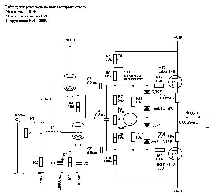
At numerous requests from radio amateurs, I present an improved and more complete hybrid ULF diagram with a detailed description, parts list and power supply diagram. The lamp at the input of the hybrid ULF 6N6P circuit was replaced with 6N2P. You can also install the 6N23P, which is more common in old lamps, in this unit. Field-effect transistors are replaceable with other similar ones - with an insulated gate and a drain current of 5A and higher.
Variable R1 - 50 kOhm is a high-quality variable resistor for the volume control. You can set it up to 300 kOhm, nothing will worsen. Be sure to check the regulator for the absence of rustles and unpleasant friction during rotation. Ideally, you should use ALPS RG - this is a Japanese company producing high-quality regulators. Don't forget about the balance regulator.
Trimmer resistor R5- 33 kOhm, zero voltage is inserted on the speaker in the ULF silent mode. In other words, by applying power to the transistors and instead of a speaker (!), connecting a powerful 4-8 Ohm 15 watt resistor, we achieve zero voltage on it. We measure with a sensitive voltmeter, since it should be absolute zero.
The diagram of one hybrid ULF channel is shown below.

The remaining resistors are 0.125 or 0.25 watts. In short, any small ones. A 10000uF capacitor can be safely reduce to 100 µF, but it is drawn according to the old designation. We set all capacitors for anad supply to 350V. If it’s difficult to get 6.8 μF, set it to at least 1 μF (that’s what I did). The quiescent current control transistor will be replaced with KT815 or KT817. This will not affect the sound, it simply corrects the current there. Naturally, we need another copy of the hybrid ULF for the second channel.

To power the transistors you need a bipolar source+-20 (35)V with a current of 4A. You can use a regular transformer. Since more power was not required, I installed a 60-watt trans from a VCR with a corresponding reduction in output power. Filtration is simple - a diode bridge and a capacitor. With a quiescent current of 0.5A, a capacity of 10,000 microfarads per channel is sufficient. Capacitors C3, C4, C5 are 160V each, no less. Or more just in case. R8 is a small tuning resistor - turned with a screwdriver. It sets the quiescent current of the output transistors (in the absence of a signal). You need to set the current from 0.3A - mode AB to 2A - mode A. In the second case, the sound quality is much better, but it will not heat up much. You can also use an electronic transformer for power supply with an additional ring and 12-turn windings - it receives 12V from the transformer, and two 20V each are the secondary. In this case, the bridge diodes must be high-frequency; simple KD202 will burn out instantly.

We feed the filament with 12 volts by connecting the filaments of both lamps in series. I took the anode voltage of 300V using a small transformer (5 watts) from a Chinese multi-voltage adapter. You can't power anything from that travesty except an LED, but in this hybrid power supply it comes in handy. We supply 12V to its 15-volt secondary from an electronic (or conventional) transformer, and remove the voltage from the 220-volt network. The current is certainly not that great, but both 6N2P lamps pull only 5mA across the anode, so they don’t need more.
- Soft, detailed and clear sound
- Excellent transmission of vocals, stage and volume
- Simple design, no configuration required
- A complete set of protections implemented on the chip chip
- High concept - a vacuum double triode acts as a current buffer. The maximum linearity of the phase response and frequency response has been achieved, an inverting connection with T-OOS has been used.
- The basis is the popular LM3886 MC manufactured by National Semiconductors
- Average power – 68 W/4 Ohm. Peak – 135 W.
The LM series amplifier chips have the best sound among analogues. This also applies to flagship models of various levels, such as LM1875, LM3876 and its logical continuation - LM3886. The author's article continues the debate on the topic of circuit design and Thorsten's developments. An amplifier based on LM3875 is being considered. Its best sound, stability and linearity is achieved with inverting switching. However, this connection, when operating on the classic output impedance of the source, has a number of disadvantages. In short: with increasing frequency, the nonlinearity of the frequency response and phase increases. This is due to the fact that with an inverting connection, the signal must come from a current source, and CD players and sound cards have an output impedance of about 200 Ohms. The current source on field-effect transistors is also eliminated due to high losses, high input capacitance and pronounced nonlinearity. A current buffer on a triode successfully copes with this task.
In addition, this kind of buffer has a voltage gain of less than 1. Due to this, the OOS depth of the microcircuit itself is reduced, which also has an extremely beneficial effect on the sound quality. It is known that deep OOS, implemented by a classical divider, coarsens and deadens the sound. In the scheme proposed by Rasmussen ( Fig.1), a T-shaped OOS has been introduced, which increases the input resistance at the inverting input and makes it possible to reduce the grounding resistance at the direct input. The disadvantage of this approach is the increase in noise and interference, but this is the first impression. If the wiring and shielding of the amplifier unit are done properly, interference will be almost invisible.
Now let’s look at what I personally didn’t like about the original scheme.
The author has LM3875 installed as a PA. Its disadvantages are imperfect protection, operation only with an 8-Ohm load, and low power. Instead, the LM3886 MC with a full set of protections and a powerful output stage was chosen, allowing it to deliver long-term power of 68 W and short-term power of 135 W into a 4-Ohm load. In addition, the amplifier is equipped with a full set of protections and a built-in mute mode.
At the exit Fig.1 There is a current limiter - a wirewound SQP resistor. The SPiKe system implemented in the LM3886 allows you to abandon it.
For the convenience of mixing channel parameters and reducing the size of the amplifier, the popular vacuum double triode 6N23P-EV was used as a buffer. It is distinguished by a low supply voltage, which is relevant in this circuit, and at the same time, good sound. Although we have to admit that in this case its application is far from classical.
For our own reasons, the following features were added to the board:
Taking into account all the above considerations, the scheme took the following form ( Fig.2):
Here are the elements C 1 , C 3 , C 4 as well as terminals CN 1.. CN 6 – common for both channels. Each channel also contains half of a double triode 6N23P-EV .
Here, let’s take a break from the circuit design of the PA for a few seconds and consider the power supply, so as not to return to this topic again.
To power the entire circuit, a four-polar power supply with a common ground and an independent heating winding is used, the circuit of which is presented in Fig.3:
Diode bridges are either ready-made or assembled from diodes of the types that appeal to you, everything from D213 to Schottky diodes. For ±36 V 0.2 A – D 1 for a voltage of at least 200 V and a current of at least 4 A. For ±27V 4 A – D 2 for a voltage of at least 100 V and a current of at least 8 A. For incandescent - D 3 for any voltage and current of at least 4 A. This seemingly overestimation of parameters is not accidental. The fact is that, despite the peak reserve of the diodes, the current during charging of the containers exceeds the nominal one several times. But the price of diodes or ready-made bridges does not differ much, so for your own peace of mind I do not advise saving.
Capacities C 1, C 2 (for voltage not less than 50 V), C 5, C 6 (for voltage not less than 35 V), C 9 (for a voltage of at least 16 V) – imported electrolytic type K50-35. C 3, C 4, C 7, C 8, C 10 – type K73-17 at 63 V.
Any power transformer with an overall power of at least 200 W that satisfies the parameters of currents and voltages in the secondary windings indicated in the diagram (incandescent current of at least 0.8 A per lamp) can be used as a transformer.
In addition, it is possible to use two separate transformers. One is powerful for powering the PA, and the other is for powering the lamp. The second can be selected from a number of standardized lamp " T transformers A butno- N Akalnye". I use TAN1.
So, we managed to fit both channels onto one printed circuit board measuring 130x80 mm. Assembled module (without additional blocking containers) C8, C9 ) looked like this ( Fig.4).
Cute, isn't it?
The original layout of the elements is shown in Fig.5:
Now a few words about the details and the intricacies of assembly.
Resistors
Most resistors require pairing across channels with an accuracy of at least 1%. These conditions are fully satisfied by resistors of the C2-23 series. So, selection is required R 1 , R 3.. R 9 . Moreover R 1 , R 3 And R 4 It is better to use metal film type MLT, OMLT or imported analogues.
Resistors R 2 And R 10 no selection required. Can be of the MLT-0.25, S1-4 or S2-23 type at 0.125/0.25 W. R 11 And R 12 – imported at 2 W. The output inductance winds over R 11 , dressed in an insulating cambric, with a wire in enamel or epoxy insulation with a diameter of 0.6-0.8 mm until filled and soldered to the legs of the resistor. Although in this case I am a resistor R 11 didn't install. Instead, a coil was soldered, wound on the handle of a file and containing 15 turns of wire with a diameter of 0.8 mm.
VR 1 , VR2 – double variable resistor. In my case, Taiwan for 44 clicks, selected with an accuracy of 0.5% from 5 pieces.
Capacitors
C 1 , C 3 , C 8 , C 9 , C 10 – polar electrolytic type K50-35, preferably imported from well-known brands. However, the circuit does not contain electrolytes in the audio circuit, which significantly improves the sound, reduces the criticality of the elemental base and increases the reliability of the system as a whole.
C1 – 16 V, C3 – 100 V, S8-S10 – 50 V.
C 4 , C 5 , C 7 , C 11 – metal film type K73-17. C 4 - at 250 V, the rest - at 63 V.
C2 – metal film or metal paper of the highest available quality, preferably no worse than polypropylene. The permissible voltage is also not lower than 63 V. Although this circuit sounds great with a K73-17 capacitor.
C6 – ceramics, preferably without piezo effect. Type KM or disk. In extreme cases, of course, the K10-17B will do, but it’s hard to imagine a worse option.
Active components
The LM3886 amplification IC can be replaced with similar pinouts, taking into account the features of each. Purely theoretically, the circuit works with any MS built on the principle of a powerful op-amp. Attention! On the MC body there is a minus power supply!
Lamp R.O. 1 6N23P-EV is changed to 6N23P or an imported analogue ECC88. It is installed in a ceramic or any other socket designed for mounting on a printed circuit board or on a UMZCH chassis and is connected to the board with copper conductors.
In addition, taking into account modern trends in design, separate amplifier blocks have been developed for L.M. 3886 , which are installed on the radiator inside the UMZCH housing, and the lamp is installed in a special socket located on the housing cover. In this version, the entire llama harness ( R 1 , R 2 , 2x R 3 , C 3 , C 4 ) is carried out by hinged mounting directly on the socket terminals. And then it is connected to the power amplification units using a shielded signal cable. Don't forget to ground the lamp shield.
The printed circuit board of one PA channel is given on Figure 6:
Since it takes about 5 s to warm up the lamp, all these 5 s the amplifier input “hangs in the air”. At this time, all imaginable interference and a very noticeable rumble are present at the output. This can be avoided in two ways - by using a mute circuit or a relay to delay the turn-on. In both cases, the control signal will be a bipolar transistor with an RC divider in the base. If the delay is not enough, simply increase the value R 1 .
A diagram of such a delay is given in Figure 7:
In addition, at the time of modeling I had relays lying around TR 81 companies TTI . A printed circuit board was laid out for them. Its drawing can also be used as a guide for wiring for any relay you like with a normally open contact group. The board layout is given on Fig.8.
Details:
VR 1 – to the supply voltage of the relay winding. You can take it a little higher (about 2 V - drop across the transistor). In my case 12 V, i.e. stabilizer 7812..7815 .
C2 – on the voltage of the PA supply arm.
C1 – higher than stabilization voltage VR 1
This protection is connected to the positive side of the PA power supply (powerful transformer). The negative power terminal and the mute circuits of both amplifier channels (or all, if there are more channels) connected together are connected to the relay.
So finally SOUND
Fans of “tube sound” will really like this amplifier. What immediately catches your eye is the excellent vocals, the stage design and its incredible depth for transistor amplifiers. Unlike the typical sound of the LM3886, the HF is not washed out in this inclusion. They sound very subtle and precise. Silver and crystal do not smudge, as in a non-inverting inclusion. It is also impossible not to note the presence of a dense, collected and powerful, but extremely well-developed bass, which has always been so difficult to achieve from LM. Jazz and Blues sound so soulful that when listening, I often found myself getting goosebumps running down my spine.
The sound of this amplifier cannot be called absolutely accurate with a multi-frequency signal, but this sound is much more pleasant to the ear than various “super-linear” designs with distortion coefficients of thousandths of a percent.
To summarize: This amplifier is intended for music, not for measurement systems. Its objective properties are questionable, but its sound and dynamic range are so mesmerizing that hearing the word “vector nonlinear distortion meter” makes you want to spit.
Moscow 2006 ( Lincor_ nobox@ inbox. ru)
This circuit of a tube-transistor headphone amplifier has been repeated by many lovers of good sound and is known in many versions, both using bipolar transistors at the output and field-effect ones.
Anyway this is Class-A. It attracts with its simplicity and repeatability, which I was also convinced of, at the same time having a desire to hear the music “performed by him.”
I bring to your attention the concept of building a hybrid single-ended circuit, the development of which was prompted by the articles “Pocket Ugly Duckling, or Pockemon-I” by Oleg Chernyshev and “Tube-semiconductor ULF” (zh. Radio No. 10 for 1997).
The first article describes a tube amplifier whose output stage is covered by a parallel negative feedback (NFE) circuit. The author complains about possible criticism for the lack of modernity of such a circuit solution (OOS and even on the first grid). However, such solutions were widely used during the golden era of tube sound engineering. See, for example, the article “Radiola Ural-52” (zh. Radio No. 11 for 1952).

I like the simplicity of implementing such an OOS: there are only two elements in the feedback circuit, these are resistors and one of them, as a rule, serves as a load for the driver stage. Such OOS does not require adaptation to the type of output lamp used (within reasonable limits). But! In the same article, the author, citing calculation formulas, says that it is necessary, depending on the output resistance of the driver stage, to adjust the values of the feedback circuit resistors.
So many “opportunities for creativity”! I installed another lamp and re-soldered a couple of resistors. It seemed wrong to me.
In my article I propose a solution to this “problem”.
They asked me to make an amplifier for sounding a room of 50 m 2, a kind of “village club”. It must be said that there is already some kind of industrial amplifier there, which is used for all kinds of events such as “disco”. That is, it plays loudly, but at the expense of quality. An amplifier was needed specifically for more or less high-quality listening to music, 30 watts per channel.

I couldn’t make a tube amplifier of such power, so I turned my attention to hybrid amplifiers.
We have it on Datagor. Let me remind you that “Corsair” is in a fan-powered configuration with a tube buffer at the input. I decided to study reviews and opinions on the Internet.
What remained was a working prototype of the SRPP on 6N23P.
It was a shame to throw it away. There was a desire to finish the amplifier to the end. In the previous craft, we had to apply some simplifications related to the size of the case, for example: common power supply for both channels, not exactly the capacities that I would like to try.
It was decided to make a new SRPP headphone amplifier on the 6N23P without these simplifications.
The result was suddenly this kind of hybrid.

Greetings, dear Datagorians!
I present to your attention a hybrid headphone amplifier based on a 6AQ8 (6N23P) tube and IRF540 field-effect transistors.

Printed circuit board drawings, installation details included, no background.
04/29/14 changed by Datagor. Amplifier circuit corrected

I have long wanted to listen to how a lamp and a stone sound in tandem. I decided to build a hybrid headphone amplifier. I looked at several diagrams. The main criterion for choosing was the simplicity of the circuit, and therefore the ease of its assembly.
I settled on two:
1) S. Filin. Tube-transistor amplifier for stereo phones.
2) M. Shushnov. Hybrid headphone amplifier. (Radiomaster No. 11 2006)
In general, these schemes are not much different from each other and without major changes you can try both one and the other. I decided to put together a diagram of M. Shushnov with field workers.
Another failed experiment led to the idea of a lamp buffer for and it turned out when I conscientiously filtered the power supply to the lamps.
It took me a long time to come up with the idea of a tube buffer, but all the failures are in the past and the idea justified itself. Not only op-amps can match resistances - a cathode follower on a suitable lamp is also suitable for this purpose.
The plane was confidently descending along the glide path, as if following an invisible thread; the runway was quickly approaching. The turbines smoothly switched to idle, the plane hovered over the runway and a second later rolled, counting the joints between the concrete slabs. The reverse flaps shifted, and the silence was cut by the sound of air being turned away by the flaps...

Alas, I heard it many times, but the reproduced sound of reverse by the flight simulator through Genius tweeters did not impress me. And listening to music without headphones did not bring any pleasure. And then I decided it was time to get decent acoustics for my computer. Without thinking twice, I wrote a message to Sergei (SGL) asking what I could buy that would please my ears. To which I received the answer, the best speaker is a self-made speaker!
Let's say. And then I received a link from him. That's how I ended up on Datagor.
Sorry about the photo, I only have a multimedia camera.
HYBRID AMPLIFIER
Many have heard and probably made tube ULFs, some say their sound is the best, while others will say that transistors are in no way inferior to them and have much better parameters.
I did both and am ready to make the final conclusion: a cool sound amplifier has both tubes and transistors, to each his own:
The lamps work great at the entrance, and they look so stylish!and field-effect transistors at the output - and there is no need for huge output transformers.
Here are the circuits that I tested during the experiments and they all worked great!


And here is an example of the practical implementation of one of the hybrid ULFs according to the scheme given below:


For this amplifier, I used a circuit based on N-channel field-effect transistors from a radio hobby magazine. The lower part of the housing, measuring 15x20 cm, made of a centimeter aluminum sheet, is used as a common radiator for the transistors. The latter are powered through a conventional diode bridge and two 10,000 uF capacitors. No AC background can be heard. 200 V for the anode is taken using a 12-volt small 10-watt trans, connected in reverse to the secondary of the main transformer. To indicate the position of the volume level, we place a blue LED through a piece of plexiglass. For beauty, the lamps from below are illuminated with red LEDs. The difference in hearing between 6N6P and 6N2P is practically unnoticeable. The setup consists of setting the required quiescent current (within 0.3 - 1 A). And lastly: don’t skimp on the radiator! Class "A" will require very decent cooling. For example, a radiator for a 100-watt ULF class “A” Mac weighs 8 kg! An electronic transformer can be used as a power source for such an amplifier, as in
Few people have tubes left, but they can still be purchased, so tube audio equipment is of constant interest to radio amateurs. You give us that same warm tube sound that has long become a meme that people like to put into place and not so much. Now let's try to combine old tube audio equipment with a more modern element base. You can get simply magical sound.
The amplifier is assembled according to a classic single-ended circuit. During the setup process, I changed some resistor values. So it was necessary to select R23, R34 so that the voltage at the anodes of the 6p14p lamp was 190V. Then, by selecting R45, we set the anode voltage on the 6n3p lamp 90-110V.

I used a BA3822LS circuit as a tone block. This microcircuit has good technical parameters and is not expensive. The main advantage of its use is the absence of a huge number of shielded wires and screens; in the absence of a signal, background noise was not heard. Connect the assembled tone block to the input of the tube ULF through 100k tuning resistors.

When making the power supply, I used a ready-made TS270 transformer and added a little more turns on top of the windings.
One rectifier is used in both channels. The output transformers are completely homemade, type TS-20.
We wind them as follows: the primary winding contains 94 turns of 0.47 wire and 900 turns of 0.18 wire; in short, in the end it should be 94/900/94/900/94/. We connect the primary winding in series, the secondary in parallel.
For the body I took sheets of three millimeter aluminum. I took the adjustment knobs from aluminum furniture handles, drilled holes to the required diameter and put them through heat shrink directly onto the variable resistors.

The power supply for the lamp stage is supplied from an unstabilized source of 300…350 volts. The filament voltage of 6.3 V does not need to be rectified or stabilized. The filament lamps of the right and left channels of the amplifier can be connected to one winding of the transformer, but it is recommended to make the anode circuits separate.


The amplifier passed the hearing test excellently - crystal clear sound, especially in the middle and top of the sound range.
The input amplifier is made using a pair of 2SK68A field-effect transistors and high-voltage bipolar 2SC1941 transistors, forming a cascade that acts as a phase inverter for the output push-pull stage on the EL34 in triode connection. This hybrid power amplifier circuit using field-effect transistors and tubes is a very high-quality sound reinforcement equipment of the highest class, so installation and soldering must be done as carefully and carefully as possible.

Static balancing of the amplifier is carried out with a 5 kOhm trimmer in the circuit for supplying a fixed bias to the control grids, and dynamic balancing with a 2-kOhm trimmer in the power supply circuit for the collectors of bipolar transistors. Despite the fact that the circuit contains transistors, the amplifier is made without OOS and has a clear “tube” sound.
Hybrid UMZCH 70 W |
This hybrid UMZF provides full power bandwidth from 30 Hz to 100 kHz and small-signal frequency response from 10 Hz to 170 kHz. The function of a voltage amplifier and phase inverter is performed by a cascade based on composite transistors Q1Q3, Q2Q4 with a current generator Q8 in the emitter circuits and an improved current mirror Q5Q6Q7 in the collector circuits.

The fixed bias on the control grids of the radio tubes is adjusted using resistor R15 so that the initial anode currents are about 40 mA. The output toroidal transformer VDV3070PP Amplimo was purchased at an online auction. Its primary winding has a resistance of 2757 ohms, its rated power is 70 W
This hybrid amplifier circuit delivers 80 W of power into an eight-ohm load with a THD of 0.04%, a bandwidth of 5 Hz - 35 kHz (20 W, -3 dB) and a signal-to-noise ratio of over 100 dB.

The only voltage amplification stage in the circuit is built on a 2SC2547E bipolar transistor with a dynamic load on an ECC88 triode.
The output stage is designed as a push-pull source follower based on a complementary pair of powerful field-effect transistors IRF640, IRF9640. Their operating point is set by trimmer PR1 during adjustment.
Capacitor C2 and resistor R9 are used to form a voltage addition circuit familiar to transistor amplifiers. In this circuit, it helps radio tube V1 to ensure normal swing of the output stage at a relatively low anode voltage.
The audio signal, through the volume control on resistor R1, enters the VL1.1 triode (control grid) of the amplifier and is amplified. The negative bias potential slightly blocks the triode formed on its control grid with the help of the anode current, which passes through resistors R3 and R4 located in the cathode circuit. The voltage will drop across these resistances, therefore, relative to the negative bus, a positive voltage of approximately +1.7V will be present at the cathode of the lamp.

On the control grid of the amplifier tube, if compared with the cathode, there will be a negative bias potential, since the grid has a common contact through resistor R1 with ground. To reduce the effect of feedback in the tube amplifier circuit there is a resistance R3, which is shunted by the electrolytic capacitance C1. Resistor R2 plays an important role as a load for the anode circuit of a tube amplifier. The voltage of the amplified audio signal generated on it is supplied through the isolation capacitor C2 to the control grid of the lamp pentode. Through the first output transformer, the signal amplified by it goes to the amplifier's loudspeaker.
Resistor R8 and capacitor C7 perform the same function as similar elements in the first stage. C6 and R6 are designed to change the timbre of the sound. Using resistor R9, a second negative feedback circuit is obtained. By capturing both stages of a tube amplifier, it reduces nonlinear distortion and creates the smoothest amplification of the audio signal across the entire audio frequency range.
The second transformer of the tube amplifier is wound on a magnetic core with a cross-section of 10 cm (W22 x 40). The primary winding is PEV-1 wire 0.2-0.25 mm 1040 turns. The secondary winding has 965 turns of the same wire, the third has 34 turns wound with PEV-1 wire 0.6-0.8 mm.
The first transformer of the TVZ21 type. It is allowed to use any output transformer from a tube TV.


