Scheme of a simple electronic clock. Electronic watches - Clocks - Designs for home and garden
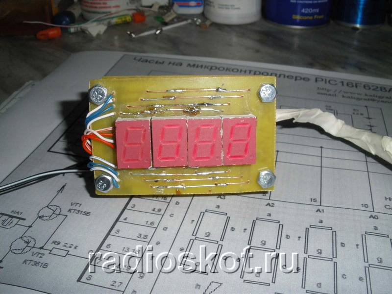
I propose for repetition the circuit of a simple electronic clock with an alarm clock, made on the PIC16F628A type. A big advantage of this watch is the ALS type LED indicator for displaying the time. Personally, I’m pretty tired of all kinds of LCDs and I want to be able to see the time from anywhere in the room, including in the dark, and not just directly with good lighting. The circuit contains a minimum of parts and has excellent repeatability. The watch was tested for a month, which showed its reliability and performance. I think of all the schemes on the Internet, this one is the easiest to assemble and run.Schematic diagram of an electronic clock with an alarm clock on a microcontroller:

As can be seen from the clock diagram, it is the only microcircuit used in this device. A 4 MHz quartz resonator is used to set the clock frequency. To display the time, red indicators with a common anode are used; each indicator consists of two digits with decimal points. In the case of using a piezo emitter, capacitor C1 - 100 μF can be omitted.

You can use any indicators with a common anode, as long as each digit has its own anode. To ensure that the electronic watch is clearly visible in the dark and from a great distance, try to choose a larger ALS.
The clock display is dynamic. At a given time, only one digit is displayed, which allows you to significantly reduce current consumption. The anodes of each digit are controlled by a PIC16F628A microcontroller. The segments of all four digits are connected together and, through current-limiting resistors R1 ... R8, connected to the terminals of the MK port. Since the indicator lights up very quickly, the flickering of the numbers becomes unnoticeable.

Momentary buttons are used to set minutes, hours and alarm clock. Pin 10 is used as an output for the alarm signal, and a cascade of transistors VT1,2 is used as an amplifier. The sound emitter is a piezoelectric element of the ZP type. To improve the volume, you can replace it with a small speaker.

The clock is powered from a stabilized 5V source. It can also be powered by batteries. The watch has 9 display modes. Switching between modes is carried out using the “+” and “-” buttons. Before the readings themselves are displayed, a short hint about the name of the mode is displayed on the indicators. The duration of the hint display is one second.
Using the "Correction" button, the alarm clock is switched to settings mode. In this case, a short-term prompt is displayed for half a second, after which the adjusted value begins to blink. Correction of readings is carried out using the “+” and “-” buttons. When you press the button for a long time, the auto-repeat mode is activated at the specified frequency. All values, except hours, minutes and seconds, are written to EEPROM and restored after power cycle.

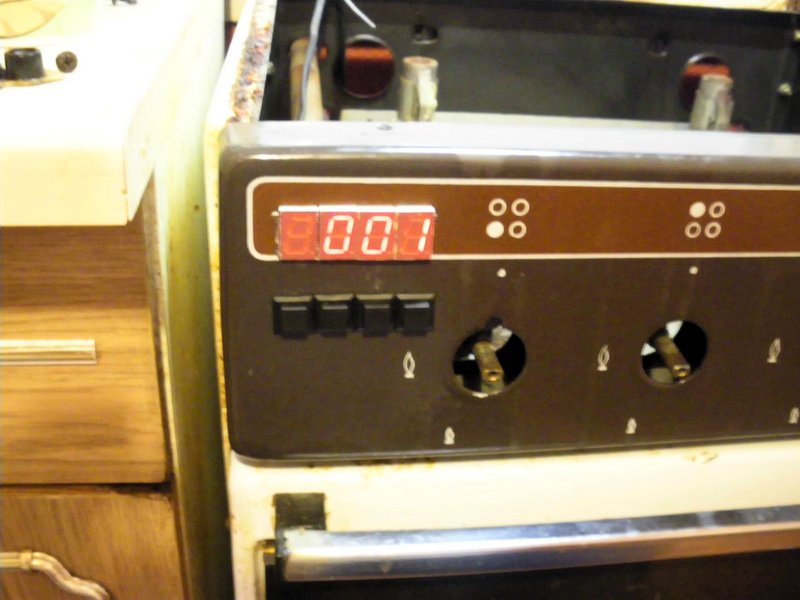
If no button is pressed within a few seconds, the electronic clock switches to time display mode. By pressing the "On/Off" button the alarm clock turns on or off, this action is confirmed by a short sound. When the alarm clock is on, the dot in the low-order digit of the indicator lights up. I was thinking about where to put the clock in the kitchen, and decided to mount it directly into the gas stove :) The material was sent by in_sane.
Discuss the article ELECTRONIC ALARM CLOCK
I remember... Thirty years ago, six indicators were a small treasure. Anyone who could then make a clock using TTL logic with such indicators was considered a sophisticated expert in his field.
The glow of the gas-discharge indicators seemed warmer. After a few minutes I was wondering if these old lamps would work and wanted to do something with them. Now it is very easy to make such a watch. All you need is a microcontroller...
Since at the same time I was interested in programming microcontrollers in high-level languages, I decided to play a little. I tried to construct a simple clock using digital gas discharge indicators.
Purpose of design
I decided that the clock should have six digits, and the time should be set with a minimum number of buttons. Additionally, I wanted to try to use several of the most common families of microcontrollers from different manufacturers. I intended to write the program in C.
Gas discharge indicators require high voltage to operate. But I didn’t want to deal with dangerous mains voltage. The watch was supposed to be powered by a harmless 12 V voltage.
Since my main goal was the game, you will not find any description of the mechanical design or body drawings here. If you wish, you can change the watch yourself in accordance with your tastes and experience.
Here's what I got:
- Time display: HH MM SS
- Alarm indication: HH MM --
- Time display mode: 24 hours
- Accuracy ±1 second per day (depending on quartz crystal)
- Supply voltage: 12 V
- Current consumption: 100 mA
Clock diagram
For a device with a six-digit digital display, multiplex mode was a natural solution.
The purpose of most elements of the block diagram (Figure 1) is clear without comment. To a certain extent, a non-standard task was to create a TTL level converter into high-voltage indicator control signals. The anode drivers are made using high-voltage NPN and PNP transistors. The diagram is borrowed from Stefan Kneller (http://www.stefankneller.de).
The 74141 TTL chip contains a BCD decoder and a high-voltage driver for each digit. It may be difficult to order one chip. (Although I don't know if anyone makes them anymore). But if you find gas-discharge indicators, 74141 may be somewhere nearby :-). At the time of TTL logic, there was practically no alternative to the 74141 chip. So try to find one somewhere.
The indicators require a voltage of about 170 V. It makes no sense to develop a special circuit for a voltage converter, since there are a huge number of boost converter chips. I chose the inexpensive and widely available IC34063. The converter circuit is almost completely copied from the MC34063 data sheet. A T13 power switch has just been added to it. The internal switch is not suitable for such high voltage. I used a choke as inductance for the converter. It is shown in Figure 2; its diameter is 8 mm and its length is 10 mm.
The efficiency of the converter is quite good, and the output voltage is relatively safe. At a load current of 5 mA, the output voltage drops to 60 V. R32 acts as a current-sensing resistor.
To power the logic, linear regulator U4 is used. There is space on the circuit and board for a backup battery. (3.6 V - NiMH or NiCd). D7 and D8 are Schottky diodes, and resistor R37 is designed to limit the charging current according to the characteristics of the battery. If you are building watches just for fun, you won't need the battery, D7, D8 and R37.
The final circuit is shown in Figure 3.
| Figure 3. | ||
The time setting buttons are connected via diodes. The state of the buttons is checked by setting a logical “1” at the corresponding output. As a bonus feature, a piezo emitter is connected to the output of the microcontroller. To shut up that nasty squeak, use a small switch. A hammer would be quite suitable for this, but this is a last resort :-).
A list of circuit components, a printed circuit board drawing, and a layout diagram can be found in the “Downloads” section.
CPU
Almost any microcontroller with a sufficient number of pins, the minimum required number of which is indicated in Table 1, can control this simple device.
| Table 1. | ||||||||||||||||
|
Each manufacturer develops its own families and types of microcontrollers. The location of the pins is individual for each type. I tried to design a universal board for several types of microcontrollers. The board has a 20-pin socket. With a few jumper wires you can adapt it to different microcontrollers.
The microcontrollers tested in this circuit are listed below. You can experiment with other types. The advantage of the scheme is the ability to use different processors. Radio amateurs, as a rule, use one family of microcontrollers and have the appropriate programmer and software tools. There may be problems with microcontrollers from other manufacturers, so I gave you the opportunity to choose a processor from your favorite family.
All the specifics of switching on various microcontrollers are reflected in Tables 2...5 and Figures 4...7.
| Table 2. | ||||||||||||
|
Note: A 10 MΩ resistor is connected in parallel with the quartz resonator.
| Table 3. | ||||||||||||
|
Note: The microcircuit must be rotated 180° in the socket.
| Table 4. | ||||||||||||
|
Note: Add SMD components R and C to the RESET pin (10 kΩ and 100 nF).
| Table 5. | ||||||||||||
|
Note: Add SMD components R and C to the RESET pin (10 kΩ and 100 nF); connect the pins marked with asterisks to the +Ub power bus via 3.3 kOhm SMD resistors.
When you compare the codes for different microcontrollers, you will see that they are very similar. There are differences in access to ports and definition of interrupt functions, as well as in what depends on the hardware components.
The source code consists of two sections. Function main() configures ports and starts a timer that generates interrupt signals. After this, the program scans the pressed buttons and sets the appropriate time and alarm values. There, in the main loop, the current time is compared with the alarm clock and the piezo emitter is turned on.
The second part is a subroutine for handling timer interrupts. A subroutine that is called every millisecond (depending on the timer's capabilities) increments the time variables and controls the display digits. In addition, the status of the buttons is checked.
Running the circuit
When installing components and setting up, start with the power source. Solder the U4 regulator and surrounding components. Check for 5 V voltage for U2 and 4.6 V for U1. The next step is to assemble the high voltage converter. Use trimming resistor R36 to set the voltage to 170 V. If the adjustment range is not enough, slightly change the resistance of resistor R33. Now install the U2 chip, transistors and resistors of the anode and digital driver circuit. Connect the U2 inputs to the GND bus and connect one of the resistors R25 - R30 in series to the +Ub power bus. The indicator numbers should light up in the corresponding positions. At the last stage of checking the circuit, connect pin 19 of the U1 microcircuit to ground - the piezo emitter should beep.
You will find the source codes and compiled programs in the corresponding ZIP file in the “Downloads” section. After flashing the program into the microcontroller, carefully check each pin in position U1 and install the necessary wire and solder jumpers. Refer to the microcontroller images above. If the microcontroller is programmed and connected correctly, its generator should start working. You can set the time and alarm. Attention! There is space on the board for one more button - this is a spare button for future expansions :-).
Check generator frequency accuracy. If it is not within the expected range, slightly change the values of capacitors C1 and C2. (Solder small capacitors in parallel or replace them with others). The accuracy of the watch should improve.
Conclusion
Small 8-bit processors are quite suitable for high-level languages. C was not originally intended for small microcontrollers, but for simple applications you can use it just fine. Assembly language is better suited for complex tasks that require critical times or maximum CPU load. For most radio amateurs, both free and shareware limited versions of the C compiler are suitable.
C programming is the same for all microcontrollers. You must know the hardware functions (registers and peripherals) of the selected type of microcontroller. Be careful with bit operations - the C language is not suitable for manipulating individual bits, as can be seen in the example of the original when for ATtiny.
Are you done? Then tune in to contemplate the vacuum tubes and watch...
...the old days are back... :-)
Editor's note
A complete analogue of SN74141 is the K155ID1 microcircuit, produced by the Minsk Integral software.
The microcircuit can be easily found on the Internet.
Homemade electronic watches, components - part 1, time measurement
- DIY or Do It Yourself
Probably every geek who is into homemade electronics sooner or later comes up with the idea of making his own unique watch. The idea is quite good, let’s figure out how and what is best to make them. As a starting point, we will assume that a person knows how to program microcontrollers, understands how to send 2 bytes over an i2c or serial port, and can solder several wires together. In principle, this is enough.
It is clear that the key function of a watch is to measure time (who would have thought, right?). And it is advisable to do this as accurately as possible; there are several options and pitfalls.
So, what methods of measuring time are available in hardware that we can use?
Built-in CPU RC oscillator
The simplest idea that can come to mind is to simply set up a software timer and use it to count down the seconds. So, this idea is no good. The clock will work, of course, but the accuracy of the built-in generator is not regulated in any way, and can “float” within 10% of the nominal value. It’s unlikely that anyone needs a watch that takes 15 minutes a month.Real time module DS1307
A more correct option, which is also used in most “folk” products, is a real-time clock. The microcircuit communicates with the microcontroller via I2C and requires a minimum of wiring (quartz and a pair of resistors). The price is about 100 rubles per chip, or about $1 on eBay for a ready-made board with a chip, a memory module and a battery connector.Scheme from the datasheet:
What is equally important, the microcircuit is produced in a DIP package, which means that any novice radio amateur can solder it. The built-in battery keeps the watch running even if the power is turned off.
It would seem that everything is fine, if not for one problem - low accuracy. The approximate accuracy of watch quartz is 20-30ppm. The designation ppm - parts per million, shows the number of parts per million. It would seem that 20 millionths is super, but for a frequency of 32768Hz it turns out 20*32768/1000000 = ±0.65536Hz, i.e. already half a hertz. By simple calculations, it can be seen that with such a difference, a generator “clicks” an extra (or missing) 56 thousand cycles per day, which corresponds to 2 seconds per day. There are different types of quartz, some users also wrote about an error of 5 seconds per day. Somehow it’s not very accurate - in a month such a watch will take at least a minute. This is already a significant difference, noticeable to the naked eye (when grandma’s favorite TV series starts at 11.00, and the clock shows 11.05, the developer of such a watch will be embarrassed in front of relatives).
However, since the temperature in the room is more or less stable, and the quartz frequency will not change much, you can add software correction. Another advice given on the forums is to use clock quartz from old motherboards; according to reviews, they are quite accurate.
DS3231 Real Time Module
We are not the first to ask the question of accuracy, and the Dallas company, following the wishes, released a more advanced module - DS3231. It's called "Extremely Accurate Real Time Clock" and has a built-in generator with temperature correction. The accuracy is 10 times higher, and is 2ppm. The price is a little higher, but the chip body is designed for SMD mounting, soldering is not so convenient, but you can buy a ready-made board on eBay.
(photo from the seller's website)
An accuracy of 6 seconds per month is already a good result. But we will go further - ideally, clocks in the 21st century do not need to be adjusted at all.
Radio module DCF-77
The method is rather exotic, but for the sake of completeness it cannot be ignored. Few people know, but precise time signals have been transmitted over the radio since the 70s. The DCF-77 transmitter is located in Germany near Frankfurt, and on the VHF frequency 77.5 KHz, precise time stamps are transmitted (yes, they already had wall and table clocks 20 years ago that did not need to be adjusted).The good thing about this method is that the circuit has low power consumption, so even wristwatches with this technology are now being produced. A ready-made DCF-77 receiving board can be purchased on ebay, the asking price is $20.

Many watches and weather stations have the ability to receive DCF-77, the only problem is that the signal practically does not reach Russia. Coverage map from Wikipedia:

As you can see, only Moscow and St. Petersburg are on the border of the reception zone. According to reviews from owners, only sometimes the signal can be received, which, of course, is not suitable for practical use.
GPS module
If the watch is located close to the window, then a very realistic method of obtaining the exact time is a GPS module. These modules can be purchased inexpensively on ebay (issue price is $10-15). For example, Ublox NEO-6M connects directly to the processor's serial pins and outputs NMEA strings at 9600 speed.
The data comes in approximately the following format: “$GPRMC,040302.663,A,3939.7,N,10506.6,W,0.27,358.86,200804,*1A”, and parsing them is not difficult even for a weak Arduino. By the way, patriots can purchase the more expensive Ublox NEO-7N module, which supports (according to reviews) both GPS and Glonass.
Obviously, the GPS module knows nothing about different time zones, so the developer will have to think through their calculation and change of summer/winter time himself. Another disadvantage of using GPS is the relatively high power consumption (however, some modules can be switched to “sleep mode” using separate commands).
WiFi
And finally, the last (and most obvious at the moment) way to get the exact time is to take it from the Internet. There are two approaches here. The first, and simplest, is to use something like a Raspberry PI with Linux as a clock board, then you don’t need to do anything, everything will work out of the box. If you want something “exotic,” then the most interesting option is the esp8266 module.
This is an inexpensive (issue price is about 200 rubles on ebay) WiFi module can communicate with the server via the serial port of the processor, if desired, it can also be reflashed (there are quite a lot of third-party firmware), and part of the logic (for example, polling the time server) can be done in the module itself. Third-party firmware supports a lot of everything, from Lua to C++, so there are quite enough options to “flex your brain.”
At this point, the topic of measuring time can probably be closed. In the next part we will take a closer look at processors and time output methods.
For those who have at least a little knowledge of microcontrollers and also want to create a simple and useful device for the home, there is nothing better than an assembly with LED indicators. Such a thing can decorate your room, or it can be used as a unique handmade gift, from which it will acquire additional value. The circuit works like a clock and like a thermometer - modes are switched with a button or automatically.
Electrical diagram of a homemade clock with a thermometer

Microcontroller PIC18F25K22 takes care of all data processing and timing, and a share ULN2803A All that remains is to coordinate its outputs with the LED indicator. Small chip DS1302 works as a timer of precise second signals, its frequency is stabilized by a standard quartz resonator of 32768 Hz. This complicates the design somewhat, but you won’t have to constantly adjust and adjust the time, which will inevitably be delayed or rushed if you get by with a random untuned quartz resonator of a few MHz. A watch like this is more of a simple toy than a high-quality, accurate timepiece.


If necessary, temperature sensors can be located far from the main unit - they are connected to it with a three-wire cable. In our case, one temperature sensor is installed in the block, and the other is located outside, on a cable about 50 cm long. When we tried a 5 m cable, it also functioned perfectly.

The clock display is made of four large LED digital indicators. They were originally common cathode, but changed to common anode in the final version. You can install any others, then simply select current-limiting resistors R1-R7 based on the required brightness. You could place it on a common board with the electronic part of the watch, but this is much more universal - suddenly you want to put a very large LED indicator so that they can be seen from a long distance. An example of such a design of a street clock is here.

The electronics themselves start from 5 V, but for the LEDs to glow brightly it is necessary to use 12 V. From the network, power is supplied through a step-down transformer adapter to the stabilizer 7805 , which produces a voltage of strictly 5 V. Pay attention to the small green cylindrical battery - it serves as a backup power source in case the 220 V network is lost. It is not necessary to take it at 5 V - a lithium-ion or Ni-MH battery for 3.6 is enough Volt.

For the case, you can use various materials - wood, plastic, metal, or integrate the entire structure of a homemade watch into a ready-made industrial one, for example, from a multimeter, tuner, radio receiver, and so on. We made it from plexiglass because it is easy to process and allows you to see the insides so that everyone can see - this watch was assembled with your own hands. And, most importantly, it was available :)

Here you can find all the necessary details of the proposed homemade digital clock design, including the circuit diagram, PCB layout, PIC firmware and
Not long ago there became a need to have a clock in the house, but only an electronic one, since I don’t like clocks, because they tick. I have quite a bit of experience in soldering and etching circuits. After scouring the Internet and reading some literature, I decided to choose the simplest scheme, since I don’t need a watch with an alarm clock.
I chose this scheme because it’s easy make your own watch
Let's get started, so what do we need in order to make a watch with our own hands? Well, of course, hands, skill (not even great) in reading circuit diagrams, soldering iron and parts. Here's a complete list of what I used:
10 MHz quartz – 1 pc., ATtiny 2313 microcontroller, 100 Ohm resistors – 8 pcs., 3 pcs. 10 kOhm, 2 capacitors of 22 pF, 4 transistors, 2 buttons, LED indicator 4-bit KEM-5641-ASR (RL-F5610SBAW/D15). I performed the installation on a one-sided PCB.
But there is a flaw in this scheme: the pins of the microcontroller (hereinafter referred to as MK), which are responsible for controlling the discharges, receive quite a decent load. The total current is much higher than the maximum port current, but with dynamic indication the MK does not have time to overheat. To prevent the MK from malfunctioning, we add 100 Ohm resistors to the discharge circuits.
In this scheme, the indicator is controlled according to the principle of dynamic indication, according to which the indicator segments are controlled by signals from the corresponding outputs of the MK. The repetition rate of these signals is more than 25 Hz and because of this, the glow of the indicator numbers seems continuous.
Electronic watches made according to the above scheme can only show time (hours and minutes), and seconds are shown by a dot between the segments, which is flashing. To control the operating mode of the watch, push-button switches are provided in its structure, which control the setting of hours and minutes. This circuit is powered from a 5V power supply. During the manufacture of the printed circuit board, a 5V zener diode was included in the circuit.

Since I have a 5V power supply, I excluded the zener diode from the circuit.
To make the board, the circuit was applied using an iron. That is, the printed circuit was printed on an inkjet printer using glossy paper; it can be taken from modern glossy magazines. Afterwards, the textolite of the required size was cut out. My size turned out to be 36*26 mm. Such a small size is due to the fact that all parts are selected in an SMD package.
The board was etched using ferric chloride (FeCl 3 ). The etching took about an hour, since the bath with the board was on the fireplace; high temperature affects the etching time; no copper was used in the board. But don't overdo it with the temperature.
While the etching process was going on, so as not to rack my brains and write firmware for the clock to work, I went to the Internet and found firmware for this scheme. How to flash MK can also be found on the Internet. I used a programmer that flashes only ATMEGA MKs.
And finally, our board is ready and we can start soldering our watches. For soldering, you need a 25 W soldering iron with a thin tip so as not to burn the MK and other parts. We carry out soldering carefully and preferably solder all the legs of the MK the first time, but only separately. For those who are not in the know, know that parts made in an SMD package have tin on their terminals for quick soldering.
And this is what the board looks like with soldered parts.


