Scheme of a New Year's garland on an avr microcontroller. Features of repairing Chinese LED garlands. Checking the status of the MK output using PINx
Happy New Year, dear users. And for the upcoming holiday, the electronic portal site decided to please you with a New Year's garland circuit on a PIC microcontroller. Let's move on to reviewing this device.
It contains four channels to which series-connected LEDs are connected, shown in the figure below:

The core of the circuit is the PIC16F628A microcontroller. The program code is written in assembly language, see listing Garland16F628ATEMP.ASM. The full cycle of in-circuit programming and debugging of the PIC16F628A microcontroller was carried out using MPLAB IDE v8.15 (integrated development environment), the MPASM v5.22 compiler (included in MPLAB IDE v8.15) and MPLAB ICD 2 (in-circuit debugger - “Debugger”). For those who do not have the tools listed above, but have their own program for working with HEX files and another programmer, you can find the file 16F628ATEMP.HEX in the corresponding project.
Microcontroller DD1 has functional outputs RB4 - RB7, to which amplifying MOSFET field-effect transistors VT1 - VT4 are connected. Technical specifications for transistors can be found on the website. The transistor drains are connected to push-in terminals X2 - X5. The load supply voltage is set by the circuit power supply, which is connected to connector X1. The maximum switched current per channel is 0.5 A. Microcontroller DD1 does not have a forced reset function; the reset pin is connected through resistor R1 to the positive supply potential. To generate the clock frequency, the microcontroller uses an on-chip clock generator. The device can be operated in the temperature range from - 40 °C to +85 °C.
The device is powered from an alternating or direct voltage source connected to connector X1. The rated voltage of the power supply is 12 V. The rated current of the power supply depends on the load and is 0.5 - 2 A. To stabilize the power supply, a conventional circuit is used: a diode bridge VD1, a linear stabilizer DA1, and filter capacitors C1 - C4.
The microcontroller is programmed with 3 lighting effects, based on the “running lights” effect:
- The garlands alternately light up and go out in one direction and repeat in the same way in the other direction.
- The garlands light up one by one and when all four garlands are lit, they begin to go out one by one in the same direction, and the same is repeated in the reverse order.
- Garlands 1 and 2, 3 and 4 alternately wink at each other.
The microcontroller is programmed to perform a predetermined number of repetitions of the lighting effect. It is worth noting that the time interval between the lighting of the garlands changes (increases, reaches a peak, and then falls), that is, the effect of “temporary swing” is visible. To better demonstrate the lighting effects, the garlands (as they are numbered in the diagram) should be placed in order in the same plane. In this case, decorate the spruce from the roots to the top (vertically, dividing the spruce into four sectors for garlands), from 1 to 4 garlands, respectively.
The power supply of the garlands is connected to the power source connected to connector X1, therefore it is necessary to calculate the series-connected light-emitting elements (LEDs, incandescent lamps). The total supply voltage is found from the sum of the voltages of the light-emitting elements connected in series. For example, there will be 6 series-connected bright LEDs designed for a voltage of 2 - 2.5 V in one garland. Since LEDs consume 20 mA, it is possible to connect series-connected LEDs in parallel in rows.


The following parts can be replaced in this unit. Microcontroller DD1 from the PIC16F628A-I/P-xxx series with an operating clock frequency of 20 MHz in a DIP18 package. Voltage stabilizer DA1 domestic KR142EN5A (5 V, 1.5 A). MOSFET field-effect transistors and VT1 - VT4 (N-channel) in an I-Pak (TO-251AA) package, analogues of the ratings indicated in the diagram are suitable. Diode bridge VD1 for an operating voltage of at least 25 V and a current of at least 2 A. Power connector X1 is similar to that indicated in the diagram with a central contact d = 2.1 mm. Non-polar capacitors C1 and C2 with a nominal value of 0.01 - 0.47 µF x 50 V. Electrolytic capacitors C3 and C4 have the same capacitive rating, and the voltage is not lower than that indicated in the diagram. Multi-colored LEDs VD1 - VD6 for voltage 2 - 2.5 V.
| This diagram is also often viewed: |
We have already learned earlier, but it is much more interesting to control this process using buttons, and the LED garland will serve as a good visual example.
Connecting a button to a microcontroller
The garland diagram is shown below.

When a button (key) is connected to a microcontroller, the corresponding MK pin must be configured as an input. In this case, the microcontroller will constantly read the state, or rather the potential level at this pin. Therefore, the program algorithm can be constructed in such a way that if at a certain pin of the MK the potential changes from high to low or vice versa, then a certain action will be performed, for example, the LED will light up.
To configure certain pins of the MK as input, zeros should be written to the corresponding bits of the DDR register. By the way, if the MK pins are not used, then it is also recommended to configure them for input. Since we will only connect buttons to port B, we will write all zeros to the DDRB register with the following command:
DDRB = 0b00000000;
When a microcontroller pin is configured as an input, it can initially be in two states, which are set using the PORT register.

If the PORT register bit is set to zero, then the pin has a high input impedance.
When the bit is set to one, a pull-up resistor is connected to the MK pin. The resistor is so called because through it a high potential (+ 5 V) is “pulled up” to the corresponding point in the electrical circuit; in this case - to the pin of the microcontroller.
Checking the status of the MK output using PINx
To know at any time what potential is present at the pin, you should check (read) the corresponding bit in the PIN register.
By analogy, this register can be compared to a sensor. You can only read information from it. You can't write anything to it. PIN is the opposite of the PORT register, which only writes to, but does not read, data.
It is more preferable to set the PORT register to one, i.e. use of internal pull-up resistor MK. This option has significant noise immunity, since to change the high potential to a low one, the output must be directly connected to ground or a common wire.
If the pin is made with a high input resistance, then any more or less powerful electromagnetic interference can induce a certain potential on it that exceeds a certain value and the microcontroller will perceive the interference as a change from low potential to high. Therefore, in our program we will use an internal pull-up resistor.
We connect one contact of the key to ground (common wire), and the second to the pin of the microcontroller. When the key is open, the output is at a high potential (+ 5 V), pulled up by the internal resistor of the MK. In this case, the corresponding bit of the PIN register will be set to one.
When you press the button, this pin will connect to the common wire (“minus”) and a low potential will appear on it. And the PIN register bit will automatically be set to zero.
Please note that the pull-up resistor also protects the circuit from a short circuit when the button is pressed.
LED garland in code
Now let's write the entire program code, and then look at its individual elements. The algorithm of the program is as follows: when the first key is closed, the “lights” will turn on in one sequence, and when the second is closed, the “lights” will light up differently. If both buttons are pressed, then all LEDs should be off.
#define F_CPU 1000000UL // Declare the operating frequency of the microcontroller 1 MHz
#include
#include
#define Z 300 // Name the delay value Z
#define VD PORTD // Assign the name VD to port D
#define K PORTB // Assign the name K to port B, to which the buttons are connected
int main(void)
DDRB = 0b00000000; // Configure port B for input
DDRD = 0b11111111; // Configure port D for output
VD = 0b00000000; // Turn off all lights
K = 0b11111111; // Turn on pull-up resistors
while (1)
if (PINB == 0b11111110) // Check if the 1st button is pressed
VD = 0b11111111; // If the key is closed, then we flash the “lights”
_delay_ms(Z);
VD = 0b00000000;
_delay_ms(Z);
else
VD = 0b00000000; // If the key is open, then all LEDs are turned off
if (PINB == 0b11111101) // Check if the 2nd button is pressed
VD = 0b00000001; // If the button is pressed, then turn on the LED one by one
_ delay_ ms(Z); // with a delay of 0.3 s
VD = 0b00000011;
_delay_ms(Z);
VD = 0b00000111;
_delay_ms(Z);
VD = 0b00001111;
_delay_ms(Z);
LED = 0b00011111;
_delay_ms(Z);
VD = 0b00111111;
_delay_ms(Z);
VD = 0b01111111;
_ delay_ms(Z);
VD = 0b11111111;
_delay_ms(Z);
VD = 0b00000000;
_ delay_ ms(Z);
else
VD = 0b00000000; // If the key is not closed, then all LEDs are turned off
Operators if And else
The purpose of preprocessors and them are well known from previous articles. What's new to us here is the if statement. If is translated from English as “if”. If the condition specified in parentheses is met, i.e. true, then the program code inside the curly braces is executed. For example, if variable a is greater than 1 unit, then variable c will be assigned the value a + b.
if (a >1)
c = a + b;
Otherwise, when the value of a is less than or equal to one, the program code in the curly braces will not be executed.
If only one command is executed in curly braces, then the C syntax allows you to simplify the notation and do without curly braces:
if (a >1) c = a + b;
The if statement also works in conjunction with the else statement.
if (a >1) → if a >1, then = a + b
c = a + b;
else → otherwise, c = a - b
c = a - b;
It works like this. If a > 1, then c = a + b. Otherwise, i.e. when a is less than or equal to one, then c = a – b.
Explanation of the program code
Now let's return to our program. If the button connected to PB0 is pressed, then a low potential appears on the pin and the corresponding bit of the PINB register is set to zero. In this case, the condition in curly brackets will be fulfilled, i.e. the garland will start flashing.
Note that the assignment command consists of a single equal sign "=", and the test command "equals" consists of two equal signs written without a space "==".
When the button is not pressed, the PINB register bit will show a one caused by the pull-up resistor being high. In this case, control will pass to the else statement and all LEDs will be turned off.
When the second key is closed, the output of which is connected to port PB1, the second program code will be executed, and the LEDs will begin to turn on one by one with a time delay of 0.3 seconds.
Thus, a garland on a microcontroller can contain a different number of LEDs and keys. Moreover, for each closing or opening of the key contacts, you can prescribe your own algorithm for the operation of the garland.
It can also be controlled with just one button. This option has a slightly more complicated code, and we will consider it in a separate article. There we will also look at how to connect powerful LEDs to the MK.

Earlier in the article, you examined in detail the configuration for output, and here - for input. Now let's put everything together and present a simple visual algorithm.
DIY garland on a microcontroller
Happy New Year, dear users. And for the upcoming holiday I decided to please you with a scheme -New Year's garland on a microcontroller pic.
And I ask you to review this article in more detail.
Device diagram:

It contains four channels to which series-connected LEDs are connected, shown in the figure below.

The core of the scheme is microcontroller PIC16F628A. The microcontroller operates according to the algorithm shown in the figure. The program code is written in assembly language, see listing Garland\16F628ATEMP.ASM.

The full cycle of in-circuit programming and debugging of the PIC16F628A microcontroller was carried out using MPLAB IDE v8.15 (integrated development environment), the MPASM v5.22 compiler (included in MPLAB IDE v8.15) and MPLAB ICD 2 (in-circuit debugger - “Debugger”). For those who do not have the tools listed above, but have their own program for working with HEX files and another programmer, you can find the file 16F628ATEMP.HEX in the corresponding project. The technical specification of the microcontroller can be found on the website and.
Microcontroller DD1 has functional outputs RB4 – RB7, to which amplifying MOSFET field-effect transistors VT1 – VT4 are connected. Technical specifications for transistors can be found on the website. The drains of the transistors are connected to push-in terminals X2 – X5. The load supply voltage is set by the circuit power supply, which is connected to connector X1. The maximum switched current per channel is 0.5 A. Microcontroller DD1 does not have a forced reset function; the reset pin is connected through resistor R1 to the positive supply potential. To generate the clock frequency, the microcontroller uses an on-chip clock generator. The device can be operated in the temperature range from – 40 °C to +85 °C.
The device is powered from an AC or DC voltage source connected to connector X1. The rated voltage of the power supply is 12 V. The rated current of the power supply depends on the load and is 0.5 - 2 A. To stabilize the power supply, a conventional circuit is used: a diode bridge VD1, a linear stabilizer DA1, filter capacitors C1 - C4.
The microcontroller is programmed with 3 lighting effects, based on the “running lights” effect.
1) The garlands alternately light up and go out in one direction and repeat in the same way in the other direction.
2) The garlands light up one by one and when all four garlands are lit, they begin to go out one by one in the same direction, and the same is repeated in the reverse order.
3) 1 and 2, 3 and 4 garlands alternately wink at each other. The microcontroller is programmed to perform a predetermined number of repetitions of the lighting effect. It is worth noting that the time interval between the lighting of the garlands changes (increases, reaches a peak, and then falls), that is, the effect of “temporary swing” is visible. To better demonstrate the lighting effects, the garlands (as they are numbered in the diagram) should be placed in order in the same plane. In this case, decorate the spruce from the roots to the top (vertically, dividing the spruce into four sectors for garlands), from 1 to 4 garlands, respectively.
Food garlands connected to the power source connected to connector X1, therefore it is necessary to calculate the series-connected light-emitting elements (LEDs, incandescent lamps). The total supply voltage is found from the sum of the voltages of the light-emitting elements connected in series. For example, there will be 6 series-connected bright LEDs designed for a voltage of 2 - 2.5 V in one garland. Since LEDs consume 20 mA, it is possible to connect series-connected LEDs in parallel in rows.
Installation of parts is one-sided. Hole sizes range from 0.7 mm to 3 mm. Files for making a printed circuit board can be found in the folder.


The following parts can be replaced in this unit. Microcontroller DD1 from the PIC16F628A-I/P-xxx series with an operating clock frequency of 20 MHz in a DIP18 package. Voltage stabilizer DA1 domestic KR142EN5A (5 V, 1.5 A). MOSFET field-effect transistors and VT1 - VT4 (N-channel) in an I-Pak (TO-251AA) package, analogues of the ratings indicated in the diagram are suitable. Diode bridge VD1 for an operating voltage of at least 25 V and a current of at least 2 A. Power connector X1 is similar to that indicated in the diagram with a central contact d = 2.1 mm. Non-polar capacitors C1 and C2 with a nominal value of 0.01 – 0.47 µF x 50 V. Electrolytic capacitors C3 and C4 have the same capacitive rating, and the voltage is not lower than that indicated in the diagram. Multi-colored LEDs VD1 – VD6 for voltage 2 - 2.5 V.
We are all familiar with Christmas tree garlands consisting of multi-colored light bulbs. However, recently products based on LEDs have become very popular.
How they are designed, what kind of connection diagram they have and what to do if the garland stops glowing will be discussed in detail in this article.
What does a Christmas tree garland consist of?
 What is a garland of LEDs, is it worse or better than a regular one?
Externally, this is almost the same product as before - wires, light bulbs (LED), control unit.
The most important element is, of course, the control unit. A small plastic box on which various operating modes of the backlight are indicated. 
They can be changed by simply pressing a button. The unit itself can be quite well protected with IP44 level of moisture and dust protection. 
What's inside? To open it, use the sharp tip of a knife or a thin screwdriver to pry up the latches from below and remove the protective cover. 
By the way, sometimes it is glued, and not just sitting on the latches.
First of all, inside you will see wires soldered to the board. The thicker wire is usually the network wire, supplying 220V voltage. 
Soldered on the board:
- the controller that creates all the lighting effects
- thyristors, each of them goes to a separate channel of the garland
- resistors
- capacitor
- and diode bridges
 The number of board elements depends primarily on the number of light channels of the garland. More expensive models may have a fuse.
LED garland diagram
The AC mains voltage is supplied to the power controller through resistors and a diode bridge, already rectified and smoothed through a capacitor. 
In this case, this voltage is supplied through the button, which is open in the normal state. When you close it, the controller modes switch.
The controller in turn controls the thyristors. Their number depends on the number of backlight channels. And after the thyristors, the output power goes directly to the LEDs in the garland.
The more such outputs, the more varied the colors the product can have. If there are only two of them, this means that only two parts (or halves) of the garland will work in different modes - some bulbs will go out, others will light up, etc. 
In fact, these two lines of diodes will be connected on two channels in series. They will connect to each other at the end point - the last LED. 
If for some reason you are annoyed by the blinking of the garland and you want it to glow evenly with only one color, it is enough to short-circuit the cathode and anode of the thyristor on the back side of the board using soldering. 
The more expensive the garland you have, the more outgoing channels and wiring will leave the control board.
At the same time, if you follow the traces of the board, one of the mains voltage outputs is always supplied directly to the final LED of the garland, bypassing all circuit elements. 
Causes of malfunction
 Situations with garland malfunctions are very diverse.
At the same time, remember that the most important element - the microcircuit on the board - “burns” very, very rarely.
In approximately 5-10% of all cases.
- Poor contact on wires
- LED in one of the light bulbs
- Capacitor
- Resistance
- One of the diodes
- One of the thyristors
- Controller chip

Bad soldering
If your backlight suddenly stops working, first of all always check the soldering of the supply and output wires. It is quite possible that the entire contact was held only by hot glue. 
It’s worth moving the wiring and contacts as usual.
The most common problem with Chinese garlands is the use of very thin wires, which simply break off at the solder points on the board.
To prevent this from happening, all contacts after soldering must be covered with a thick layer of hot-melt adhesive. 
And when stripping such veins, it is advised to use not a knife, but a lighter. Instead of whittling away the insulation with a blade, lightly heat and melt it with a lighter. 
After that, simply remove the outer layer with your nails without damaging the veins themselves.
LED damage
If the wire contacts are OK and you are sinning on one of the diodes, how can you check if it is faulty? And most importantly, how to find it among the whole series of light bulbs? 
First of all, unplug the garland from the outlet. Start with the last diode. The power wire comes to it directly from the control unit.
An outgoing conductor is soldered to the same leg. He goes to the next branch of the light channel. You also need to test the diode between its two power wires (input-output). 
You will need a multimeter and its somewhat modernized probes. 
Thin needles are tightly tied to the tips of the tester probes with a thread so that their points protrude a maximum of 5-8mm. 
Wrap everything on top with a thick layer of electrical tape. 
Since the LEDs are soldered, you won’t be able to simply pull them out of the light bulb like in conventional garlands.
Therefore, you will have to pierce the insulation of the conductors to get to the copper conductors of the wiring. Switch the multimeter to diode testing mode. 
And you begin to sequentially pierce the supply wires near each suspicious diode. 
If you have a garland not 220V, but 12V or 24V, which is connected from this power supply: 
then the working LED from the multimeter battery should light up. 
If this is a 220V backlight, then check the multimeter readings.
On working elements they will be approximately the same, but the faulty one will show a break.
The method is of course barbaric and damages the insulation, but it works quite well. True, after such punctures, it is better not to use outdoor garlands outdoors.
Chaotic blinking
 There is a situation when you turn on a garland and it starts blinking chaotically, sometimes brighter, sometimes dimmer. It sorts through the channels on its own.
In general, one gets the impression that this is not some kind of factory effect, but as if the garland has “gone crazy.”
Most often the problem here is the electrolytic capacitor. It may swell and swell a little, and this will be clearly visible even to the naked eye. 
Everything can be solved by replacing it. The denomination is indicated on the case, so you can easily purchase and select a similar one in radio parts stores. 
If you replaced the capacitor, but it did not give any effect, where to look next? Most likely one of the resistors has burned out (broken). It is quite problematic to visually determine the breakdown. You will need a tester.
You take resistance measurements, having previously learned its nominal (normal) value from the markings. If it doesn't match, change it. 
Part of the garland does not shine
When any of the channels on the garland does not work completely, there may be two reasons.
For example, a breakdown on one of the thyristors or diodes responsible for it.
To make sure of this for sure, simply unsolder the wiring of this channel on the board from its place and connect there the adjacent channel, which is known to be working. 
And if at the same time another channel also stops working, then the problem is not in the garland itself, but in the components of its board - a thyristor or diode. 
You check them with a multimeter, find the ones that match the parameters and change them.
The garland shines dimly
There are also not entirely obvious accidents, when the LEDs of a separate channel seem to be on, but rather dimly compared to the others. 
What does it mean? The controller circuit is working fine. When you press the button, all modes are switched.
Testing the parameters of the diode bridge and resistance with a tester also does not reveal any problems. In this case, the only thing left to blame is the wires. They are already quite frail, and when such a multi-core wire breaks, its cross-section decreases even more.
As a result, the garland is simply not capable of starting the LEDs in the nominal brightness mode, since they simply do not have enough voltage. How to find this torn vein in a long garland? 
To do this, you will have to walk along the entire line with your hands. Turn on the garland and start moving the wires near each LED until all the backlight lights up at full strength.
According to Murphy's Law, this may be the very last piece of garland, so be patient.
As soon as you find this area, pick up a soldering iron and disassemble the wires on the LED. Clean them with a lighter and solder everything again. 
Then insulate the soldering area with heat shrink. 
They asked me to somehow assemble a simple and inexpensive garland on a microcontroller. I came across the cheapest eight-bit AVR microcontroller Attiny13. In this article I want to describe step by step the process of assembling this device.
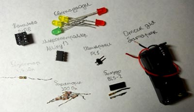
From the details we will need:
Microcontroller Attiny13 - 1 pc.
DIP-8 socket - 1 pc.
Resistor 4.7 kOhm - 1 pc.
Resistor 100 Ohm - 5 pcs.
PLS pins - 2 pcs.
LEDs (any) - 5 pcs.
BLS-2 socket - 1 pc.
Battery compartment - 1 pc.
I divided the assembly of the device into several stages:
Stage 1. Making the board
Stage 2. Soldering radio parts onto the board
Stage 3. Manufacturing a programmer for flashing the microcontroller firmware
Stage 4. Microcontroller firmware
Stage 1. Making the board
Attention! It is absolutely not necessary to make a board; you can use a breadboard. But it’s still better and more beautiful to make a board for the device.
So, first we need the following:
A piece of textolite (size 45 by 30 mm)
Small capacity
Water
Permanent marker
A little technical alcohol or cologne
Eraser
The surface of the PCB is covered with copper foil, and foil, like any other metal, has the property of oxidizing in air. Therefore, let’s take an eraser and wipe the copper part of the PCB.


Did you draw it? Great. Now you need to etch the board using ferric chloride.
During etching, ferric chloride eats away (not painted over with a marker) part of the copper coating of the textolite.

And so, since ferric chloride is a powder, we need to dilute it in water.
Here is the proportion: 100g. ferric chloride per 700 ml of water. But we don’t need that much, so we take 10g. per 100 ml. water. Next, we lower our board into this solution.

And we wait for about two hours (until the ferric chloride solution eats away the unpainted part of the copper coating of the PCB).
After the board has been etched, take it out of the container and rinse it under running water.

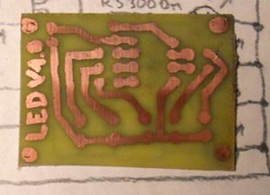
Here's a photo of the etched board.

Now we erase the marker from the board (technical alcohol or cologne is great for this).

Since I don't have an electric drill I use my school compass

After all the holes have been made in the board, you need to clean it with fine sandpaper.

Now turn on the soldering iron and tin the board. Below is a photo of the tinned board.

Any rosin remaining on the board can be wiped off with industrial alcohol or nail polish remover.

The board is ready! Stage 1 completed!
Stage 2. Soldering radio parts onto the board
After you have made the board (or maybe someone didn’t make it, but decided to use a breadboard), you need to solder the radio parts onto it.
Diagram of an LED garland on the Attiny13 microcontroller:
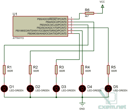
We solder the radio parts onto the board (according to the diagram above) and get the following device:

The entire device is almost ready, all that remains is to flash the microcontroller.
Stage 2 completed!
Stage 3. Manufacturing a programmer for flashing the microcontroller firmware
Attention! If you already have a programmer for AVR microcontrollers, you can skip this step and flash the microcontroller yourself! You can download the firmware from the link at the bottom of the page.
We will assemble the programmer on the LPT port of the computer. Here is the programmer diagram:

In the picture in the rectangle (where the LPT port is) is the contact number where to connect the wiring. Try to make the wires shorter (no more than 20 cm). If the wires are longer than 20 cm, then during the firmware or reading of the microcontroller there will be errors that can cost the microcontroller its life!
Be very carefulThe LPT port is very easy to burn!
To make a programmer we will need:
25-pin connector for LPT port (male)
Resistors 150 Ohm 4 pcs.
Resistor 10 kOhm 1 pc.
3 volt battery
Here is my version of the programmer:

Now you can start flashing the microcontroller firmware.
Stage 4. Microcontroller firmware
Attention! This stage describes the firmware of the Attiny13 microcontroller using a program and a programmer for the LPT port.
Everyone knows that without firmware, a microcontroller is a chip that does nothing, and in order for it to control our garland, we need to flash it.
For firmware we will use the LPT programmer we previously made, a computer and the PonyProg2000 program.
First, download the firmware for the garland (link at the bottom of the page), then download the PonyProg2000 program from the Internet and install it.
Now everything is almost ready for flashing the microcontroller firmware. All that remains is to connect the microcontroller to the programmer and connect the programmer to the computer.
After everything is connected, launch the PonyProg2000 program.
The following window will pop up:

In the window, click the “Yes” button.
After calibration, the following message will appear:

That's it, the program is calibrated!
Now go to the settings (Setup > Interface Setup…). The following window will appear:
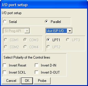
Then in the main program window select “AVR micro”, “Attiny13”

Now all that remains is to open the firmware; to do this, select “Open Device File…” in the “File” menu. In the "File type:" list, select "*.hex" and indicate the path to the firmware of our LED garland, click the "Open" button.

In the main window, click on the "Write device" button:

After this message appears:

The microcontroller is flashed and operational! But wait, we still need to set the fuse bits. By the way, fuse bits are a section (4 bytes) in AVR microcontrollers in which the operating configuration of the microcontroller is stored.
To set fuse bits, in the “Command” menu, select “Security and Configuration Bits...”, in the window that appears, click the “Read” button and check the boxes as in the picture below:

After checking the boxes (as in the picture above), click the "Write" button. All is ready!
Now turn off the computer and remove the microcontroller from the programmer, insert the microcontroller into the socket on the garland board. If everything is done correctly, then when power is applied (3 volts) the garland should work!

In conclusion, I would like to say that I wrote the program in an environment (the source is attached), the program has 9 effect subroutines, so nothing prevents you from creating your own effects.
By default the device has 4 different effects:
1. Running point
2. Running line
3. LED switching
4. Blinking
You can download the firmware, sources, project in Proteus below
List of radioelements
| Designation | Type | Denomination | Quantity | Note | Shop | My notepad | |
|---|---|---|---|---|---|---|---|
| Garland | |||||||
| U1 | MK AVR 8-bit | ATtiny13 | 1 | To notepad | |||
| R1-R5 | Resistor | 300 Ohm | 5 | To notepad | |||
| R6 | Resistor | 4.7 kOhm | 1 | To notepad | |||
| D1-D5 | Light-emitting diode | 5 | To notepad | ||||
| Panel | 1 | DIP-8 | To notepad | ||||
| Resistor | |||||||


