Computer ports, connectors and buttons. USB: types of connectors and cables for a smartphone
External devices are connected to connectors and sockets located on the outside of the PC system unit (back and front sides) or laptop (sides or back):


The response connectors look like this:

 Power cables(220 V)
 power unit ASUS laptop
 PS/2 plugs for connecting a keyboard (purple) and mouse (green).
 LPT cable. The LPT (parallel port) port was mainly used to connect printers. Modern printer models provide connection to a USB port.
 COM cable. COM port (serial port) is mainly used to connect modems.
 USB cable. The USB port was developed later than the above ports. Most peripheral devices are connected via the USB port: modems, printers, scanners, flash drives, portable hard drives, digital cameras, etc.

VGA cable. Used to connect a monitor.  Cable for connecting to the Internet (Intranet) ( RJ-45 connector)
 Slot connector types used on the motherboard (ISA or EISA, PCI, AGP):
Slots with PCI connector (female):

and sound card with PCI connector (male):

PCI connectors used to connect an internal modem, sound card, network card, SCSI disk controller.
 ISA slots (Mother). The ISA interface is deprecated. In modern PCs, it is usually absent.
PCISA FlipPOST diagnostic board with connectors PCI and ISA (male) PCZWiz company

Slot with AGP connector(dad is at the top, mom is at the bottom).

The AGP interface is designed to connect a video adapter to a separate bus, with output directly to system memory.
UDMA slot(father is on the right, mother is on the left).  Hard drives and more are connected to it.
It should be noted that each slot type has its own color. By opening access to the motherboard, you can easily find your way around. But it’s better that you don’t need it. But the cables that connect external devices to the PC “you need to know by sight.” Remember that the mother and father of the connector must be the same color. Always remember to match the colors of the male and female connectors or know what the colors of the connectors on the PC (laptop) case indicate.
Take, for example, a standard sound card:

Linear audio output to the speaker is always green.
The line input for audio amplification is always blue.
The microphone connector is always pink.
Match them with plugs:
 The color design of the connectors will help you. True, colors among PC manufacturers are not unified. For example, some may have a purple keyboard connector, while others may have a red or gray one. Therefore, pay attention to the special symbols that mark the connectors. In this case, it will not be difficult for you to find out.
Decoding computer connector symbols


Appearance of computer and laptop ports

The interface cables for external devices are unique. You cannot insert it into another connector on your PC (the design and number of sockets are different). All this will help you move your PC (laptop) from place to place without prompting from anyone. You will be able to connect devices and cables to your PC correctly. I hope that the material presented will help you with this.
Now let's look at each connector in more detail. Let's start from top to bottom in order. First on the list will be socket for connecting the power cable: Standard power cable, this cable connects all computer devices, from printers and scanners to faxes and monitors. A very convenient cable, differing only in the length of the wire and the thickness of the wire section. Accordingly, the thicker the cable, the greater the load it can withstand. PS/2 connector used for connecting mouse and keyboard. In their visual appearance they are absolutely identical, the only difference is in their coloring. The green port is for connecting a mouse, the purple port is for connecting a keyboard. In modern motherboards you can find one PS/2 port, which is painted in two colors at once, green and purple, this means that you can connect either a mouse or a keyboard to it. COM port– was once used to connect a mouse, modems, scanners. Now this port is practically not used. Over the past 7 years, I have had to use this port several times. To connect temperature sensors to it. It was through this port that the data accumulated on it was read. I also connected an attachment for satellite dishes through this port (updating the firmware). VGA port – for connecting a monitor. The port is very similar to the previous one, but has three rows of contacts and is always painted blue. This port has been used for connecting monitors for many years. Now new video cards with a DVI port are being actively introduced (photo on the right). When choosing a monitor with such a cable, I advise you to carefully check which DVI port you have on your motherboard, since there are at least five different types. LPT port– previously used to connect a printer or scanner. Now this port is obsolete and no one uses it. The outdated LPT port has been replaced by a new, more functional USB port. In modern motherboards this port is not installed as unnecessary. USB port- The most widely used connector in any modern computer. You can connect a mouse, keyboard, camera, flash drive, printer, scanner, video camera and much more to this connector. There are two types of USB ports – USB 2.0 and USB 3.0. The USB 3.0 port has a blue color inside; this port has a high throughput speed. USB 2.0 ports are white and black. Network port – for connecting a network cable. A cable from the provider that provides you with Internet service is connected to this port. The same ports are present on your router (if you use one). This port can be used to connect audio devices. For connecting speakers, headphones, microphones, etc. Red connector for connecting a microphone, green connector for connecting speakers (headphones), blue connector for line output (for transmitting an audio signal to another device).
Hard drive connectors
In the process of computer development, HDD or hard drive changed several connector specifications; for many modern computer scientists, names such as IDE, SCSI and their modifications are already history. The dimensions of the hard drive have also changed significantly; the first bricks I had to work with weighed more than a kilogram!
At the moment, the following hard drive connectors are relevant:
The SATA connector is the most popular nowadays; hard drives with this interface are found in computers, laptops, servers, video recorders and other computer equipment.

There are from 4 to 8 SATA connectors on the computer motherboard. Not only hard drives are connected through this interface. CD-ROM, DVD-ROM drives also use it.
MSATA connector— Variety SATA connector, designed specifically for solid state drives (SSDs), which have replaced mechanical hard drives. SSD drives with this interface are found in computers, laptops, servers, video recorders, and other computer equipment.
The motherboard has many connectors for connecting various devices. This is the processor, video card, RAM and others. Sometimes, for some reason, they prefer to use not the built-in sound and network cards, but separate ones installed in PCI And PCI-E connectors. There are usually no problems connecting them; just install the card in its slot. But sometimes there is a need to completely disassemble the computer and independently replace the motherboard for the purpose of an upgrade, or a burnt-out board with a similar new one. There is nothing super complicated about this, but, as with everything, there are some nuances. For the motherboard and the devices installed on it to work, you need to connect power to it. In motherboards manufactured before 2001-2002, power was supplied to the motherboards using a connector 20 pin.
Power connector 20-pin female
This connector had a special latch on the body to prevent spontaneous removal of the connector, for example, in the event of shaking during transportation. In the picture it is at the bottom.

With the advent of Pentium 4 processors, a second 4-pin 12 volt connector was added, connected separately to the motherboard. These connectors are called 20+4 pin. Around 2005, power supplies and motherboards began to go on sale 24+4 pin. This connector adds 4 more contacts (not to be confused with 4 pin 12 volts). They can be connected to a common connector and then 20 pin turn into 24 pin, or connect with a separate 4 pin connector.

This is done for power compatibility with older motherboards. But in order for the computer to turn on, it is not enough to supply power to the motherboard. This is in ancient computers that had AT format motherboards, the computer was turned on after power was supplied to the power supply, using a switch or a power button with a lock. In ATX format power supplies, to turn them on, you need to short-circuit the power supply terminals PS-ON And COM. By the way, you can check an ATX format power supply in this way by shorting these pins with a wire or an unbent paper clip.

Turning on the power supply
In this case, the power supply should turn on, the cooler will begin to rotate and voltage will appear at the connectors. When we press the power button on the front panel of the system unit, we send a kind of signal to the motherboard that the computer needs to be turned on. Also, if we press the same button while the computer is running and hold it for about 4-5 seconds, the computer will turn off. Such a shutdown is undesirable because programs may malfunction.

Power switch connector
Computer power button ( Power) and reset button ( Reset) are connected to the computer motherboard using connectors Power switch And Reset switch. They look like two-pin black plastic connectors with two wires, white (or black) and colored. Using similar connectors, a power indication is connected to the motherboard, on a green LED, labeled on the connector as Power Led and a hard drive operation indicator on the red HDD Led.

Connector Power Led It is often divided into two connectors with one pin each. This is done due to the fact that on some motherboards these connectors are located next to each other, just like HDD Led, and on other boards they are separated by a pin space.

The figure above shows the connection of connectors Front panel or the front panel of the system unit. Let's look at the connection in more detail Front panel. Bottom row, on the left, the connectors for connecting the hard drive LED (HDD Led) are highlighted in red (plastic), followed by the connector SMI, highlighted in blue, then the connector for connecting the power button, highlighted in light green (Power Switch), followed by the reset button, highlighted in blue (Reset Switch). Top row, starting from the left, is the Power LED, dark green (Power Led), Keylock brown, and speaker orange (Speaker). When connecting the connectors of the Power Led, HDD Led and Speaker, the polarity must be observed.

Beginners also have many questions when connecting to the front panel USB connectors. The connector strip located on the back wall of the computer and the internal card reader are connected in the same way.

As can be seen from the two figures above, card readers and strips are connected using an 8-pin fused connector.

But connecting USB connectors to the front panel is sometimes difficult because the pins of this connector are disconnected.

Connection USB to the motherboard - diagram
They have markings similar to those we saw on the front panel connectors. As everyone knows, the USB connector uses 4 contacts: power supply +5 volts, ground and two contacts for data transfer D- and D+. In the connector for connecting to the motherboard we have 8 pins, 2 USB ports.

If the connector still consists of individual pins, the colors of the connected wires can be seen in the figure above. In addition to the power, reset, indication and USB connectors, the front panel has microphone and headphone jacks. These sockets are also connected to the motherboard with separate pins.

The connection of the sockets is organized in such a way that when connecting headphones, the speakers connected to the socket are disconnected Line-Out on the back of the motherboard. The connector to which the jacks on the front panel are connected is called FP_Audio, or Front Panel Audio. This connector can be seen in the figure:

The pinout or pin arrangement on the connector can be seen in the following figure:

fp audio connection
There is one caveat here if you used a case with jacks for a microphone and headphones, and then wanted to change to a case without such jacks. Accordingly, without connecting the connectors fp_audio to the motherboard. In this case, when connecting speakers to the connector Line-Out there will be no sound from the motherboard. In order for the built-in sound card to work, you need to install two jumpers (jumpers) on 2 pairs of contacts, as in the figure below:

Such jumpers are used for installation on motherboards, video, sound cards and other devices to set operating modes.

The structure of the jumper inside is very simple: it has two sockets that are connected to each other. Therefore, when we put a jumper on two adjacent pins - contacts, we close them together.

Also on motherboards there are soldered connectors for LPT and COM ports. In this case, a strip with the corresponding connector on the rear wall of the system unit is used for connection.

When installing, you need to be careful not to connect the connector incorrectly, on the contrary. Motherboards also have connectors for . Their number, depending on the motherboard model, is equal to two in cheap motherboard models, and up to three in more expensive ones. The processor cooler and the blow-out cooler located on the rear wall of the case are connected to these connectors. The third connector can be used to connect a cooler installed on the front wall of the system unit for blowing, or a cooler installed on the chipset radiator.

All these connectors are interchangeable, since they are mostly three-pin, with the exception of four-pin connectors for connecting processor coolers.
You just bought a TV and, looking under the back panel, you have absolutely no idea what each one is for connector. Where to connect your home DVD player? How to output sound to external speakers? And is it possible to connect the TV to a computer? If you don’t understand anything about this, then this article was written especially for you. In fact, there is nothing complicated about this; all the variety of connectors can be reduced to certain types, which is what we will do now, in fact.
Video connectors
One of the types in any TV are VIDEO connectors. Let's take a closer look at each of them.

The abbreviation of this connector stands for High-Definition Multimedia Interface. What does it mean in Russian as Interface for High Definition Multimedia. Nowadays, this interface is the best option for connecting any video equipment to TV, as it allows you to transmit digital video, even HD, and plus digital audio up to 8 channels. All new TVs are equipped with one or even several of these connectors. It is also present in almost all models of household equipment capable of producing a video signal: Blu-ray and DVD players, game consoles, laptops, simple video cards for PCs, video cameras and some smartphone models.
PC / VGA In / Analog RGB

This connector is of the D-subminiature family, which is designed to connect a computer to a TV. This connector transmits analog signal, so the image quality here is inferior to digital signal connections.

This connector is a European standard for connecting various multimedia devices. Not only analog audio and video signals, but also control signals can be transmitted via SCART. As for the quality of the resulting image, it is comparable to a component connection, but is certainly inferior to HDMI.

Fully stands for Separate Video, which means Separate Video. This connector is so called because it transmits the video signal in the form of two separate signals, color and brightness. The image quality falls between component and composite. Nowadays it is almost never used.
Component (Y/Pb/Pr)

Perhaps the best option for connections source of analog signal to TV. This connector uses three separate cables to transmit the video signal: the brightness level (Y), the difference between the red level and brightness (Pr) and the blue level and brightness (Pb). There is no mixing of signals, as, for example, in S-Video and a composite connection, so the image quality for an analog signal is the highest possible. There are also two connectors for transmitting audio signals.
Composite (CVBS)

A composite connection is the worst option for connecting a video source to a TV, since three analog signals (brightness, saturation and hue) are transmitted over one cable at once. It is recommended to be used only in the most extreme cases. Next to the video connector, as a rule, there is a pair of inputs for audio signals.
Audio connectors

Modern TVs can also be equipped with analog audio inputs. Basically, these are a pair of RCA connectors, or as they are popularly called “tulips”, one of which is red for the right channel and white, which is for the left channel in a stereo or mono channel. There is also a mini-jack, which is used to connect miniature audio equipment.
In addition to TV inputs, there may also be audio outputs. Often this is a mini-jack for headphones. But there are also digital ones for optical and coaxial cables. The first is a TOSLINK connector, and the second is an RCA connector, exactly the same as that used for audio input.
Other connectors
In addition to AUDIO and VIDEO connectors, there are also other connectors intended for other purposes. Let's look at the most common of them.
Antenna/RF In

As you probably already guessed, a regular TV antenna is connected here. But in addition to this, some video devices can also be connected, for example old VCRs.

This is a network port. Using it you can connect your TV to a local network or the Internet. This way you can use multimedia data from your PC or access various online services.
Mobile device users had a hard time in the 2000s - they were forced to put up with the so-called proprietary. The phones of each manufacturer were equipped with unique charging connectors - as a result, the charger, for example, for Nokia did not work with a Motorola phone. It even got to the point of absurdity - when for two phones from the same manufacturer (Finnish) we had to look for different chargers. The dissatisfaction of users was so strong that the European Parliament was forced to intervene.
Now the situation is completely different: almost all smartphone manufacturers equip their gadgets with ports for chargers same type. The user no longer has to buy a new charger “in addition” to the phone.
USB cables can be used not only to transfer data from a PC to a gadget, but also to charge a mobile device. Smartphones are capable of replenishing battery “reserves” both from an outlet and from a computer, but in the second case, charging will take significantly longer. A traditional USB cable for an Android or Windows Phone smartphone looks like this:
There is a standard plug at one of its ends USB 2.0 Type-A:
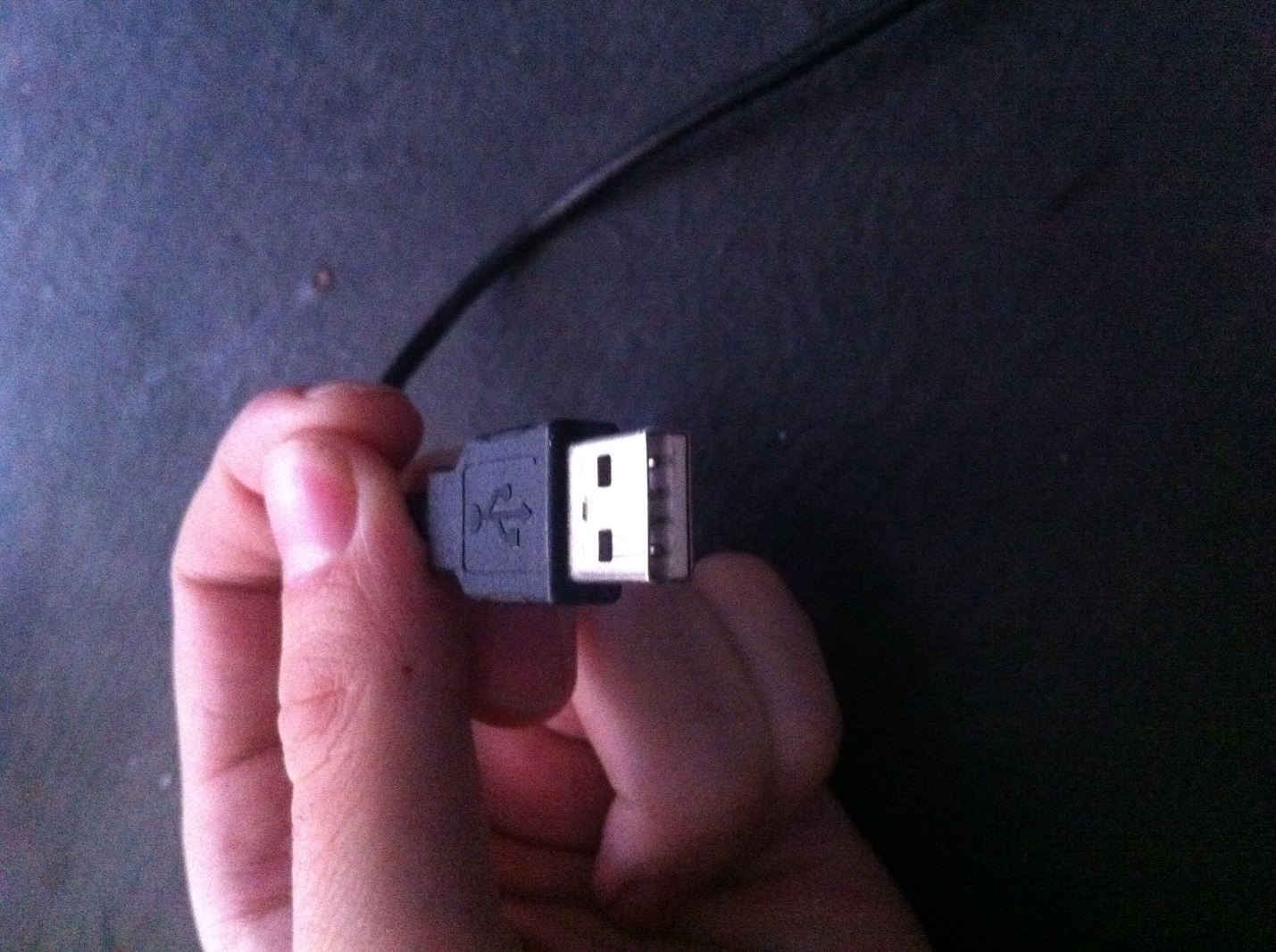
This plug plugs into the USB port on your computer or laptop.
At the other end of the wire there is a plug microUSB.
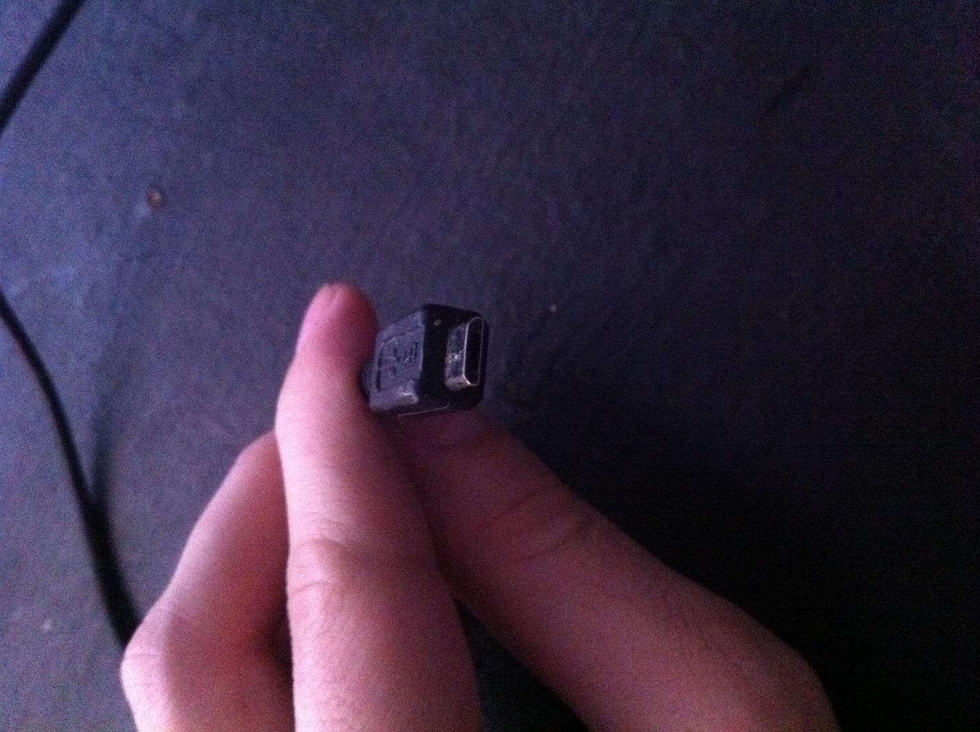
It is, accordingly, inserted into the micro-USB connector on the mobile device.
Micro-USB 2.0 is now a unified connector: it can be found on smartphones and tablets from almost all mobile device manufacturers (with the exception of Apple). An agreement on interface standardization was signed in 2011 by representatives of 13 leading companies in the mobile market.
The choice fell on Micro-USB for a number of reasons:
- The connector is compact. Its physical dimensions are only 2x7 millimeters - this is about 4 times smaller than USB 2.0 Type-A.
- The plug is durable– especially when compared with the Nokia thin charger.
- The connector is capable of providing high data transfer rates. Theoretically, the transfer speed via Micro-USB when using the 2.0 standard can reach 480 Mbit/s. The actual speed is much lower (10-12 Mbit/s in Full Speed), but this rarely causes inconvenience to users.
- The connector supports the OTG function. We'll tell you more about the benefits this provides later.
Micro-USB could impose competition in the fight for the role of a standard connector Mini-USB. The mini plug looks like this:

This type of USB connector was not suitable as a standard one, and here’s why:
- The connector is larger in size– albeit not by much. Its size is 3x7 millimeters.
- The connector is quite fragile– due to the lack of rigid fastenings, it becomes loose very quickly. As a result, transmitting data via cable becomes a real pain for the user.
In the 2000s, a mini-USB connector could be found on smartphones from “second-class” manufacturers - say, Philips And Alcatel. Nowadays you won’t find mobile gadgets with a mini-jack on the market.
In addition to the USB connectors we mentioned (Micro-USB, Mini-USB, USB Type-A), there are others. For example, micro-USB standard 3.0 can be used to connect hard drives to a PC, and USB Type-B(square shape) – for musical instruments (in particular, MIDI keyboards). These connectors are not directly related to mobile technology (except for Galaxy Note 3 c USB 3.0), so we won’t talk about them in more detail.
What types of USB cables are there for smartphones?
Thanks to the inexhaustible imagination of Chinese handicrafts, mobile technology users can buy cables of completely different configurations. For example, in the era of proprietaryism, the following “monster” was incredibly popular:

Yes, this charger fits all the main connectors!
Similar “multi-tools” are still on sale, but they have fewer plugs. Here is a 4-in-1 charger, which can be ordered for less than 200 rubles:

This charger is equipped with all modern plugs - Lightning, 30Pin (both for iPhone), microUSB, USB 3.0. Definitely a “must-have” for the user!
There are other interesting options. Here is the cable from OATSBASF For those who hate cables:


This cable allows you to charge two mobile devices from your computer. simultaneously(for example, the 5th iPhone and Android) and has a very tempting price - just over 100 rubles.
In domestic stores and showrooms, the user, of course, will not find such an abundance of different cables as on the pages of catalogs GearBest And AliExpress. In addition, data equipment at retail costs significantly more. For these two reasons, users are recommended to order USB cables from China.
What is the OTG standard?
Surely many have seen such a cable and wondered what it is for:

This is a cable OTG; at one end there is a plug micro-USB, on the second – connector USB 2.0, "Mother". Using such a cable, you can connect a USB flash drive to a smartphone or tablet, but only if the mobile device itself supports the standard OTG.
OTG(short for On-The-Go) is a function designed to quickly connect 2 USB devices to each other, without the mediation of a computer. Connect by OTG You can use not only a flash drive (although this, of course, is the most common case), but also, for example, a computer mouse, keyboard, external hard drive, gaming steering wheel, joystick. You can even connect your smartphone to a printer or MFP to print out a photo taken with the gadget’s camera.
Cables OTG for the iPhone have also already appeared, but you can only download photos and videos to an Apple device (without jailbreak) from an external storage device – and then only when the root folders on the flash drive and the photos themselves have the “correct” names.
A complete list of smartphones that support the function OTG, no - simply because almost all modern gadgets can boast of having this standard, and the list would be huge. However, a buyer who intends to connect a mouse or flash drive to the device should inquire from a store consultant about support OTG before giving away money - “just in case.”
USB Type-C: what are the advantages?
Transition from micro-USB This is a new trend in the mobile electronics market! Manufacturers are actively mastering the technology and equipping their flagship models with improved connectors for charging and data transfer. USB Type-C waited a long time “in the shadows”: the connector was created back in 2013, but only in 2016 did market leaders pay attention to it.
Looks like USB Type-C So:

What are the advantages? Type-C in front of everyone familiar micro-USB?
- High data transfer speed. Bandwidth Type-C equals 10 Gb/sec (!). But that's just bandwidth.: in reality, only owners of smartphones with the standard can count on such speed USB 3.1- For example, Nexus 6P And 5X. If the gadget uses the standard USB 3.0, the speed will be around 5 Gb/sec; at USB 2.0 Data transfer will be significantly slower.
- Fast charging. The duration of the smartphone charging procedure depends on the potential number of watts supplied by the connector. USB standard 2.0 capable of serving everything 2.5 W– that’s why charging lasts for hours. Connector USB Type-C provides 100 W– that is, 40 times (!) more. It is curious that current transmission can occur in both directions - both to the host and from it.
- Connector symmetry. If the connector micro-USB there is up and down, then the connector Type-C symmetrical. Which side you insert it into the connector does not matter. From this point of view, technology USB Type-C similar to Lightning from Apple.
Dignity Type-C The size of the connector is also small - only 8.4 × 2.6 millimeters. According to this technology criterion micro-USB And USB Type-C similar.
U USB Type-C There are also disadvantages, one of which is more than significant. Due to the unregulated operation of the connector, charging can easily “fry” the mobile device. This probability is not purely theoretical - fires have occurred in practice. It is for this reason that the proliferation of non-original, “makeshift” cables and chargers USB Type-C Type-C and decide to abandon the standard connector. At the same time, Ravencraft admits that, perhaps, complete replacement USB-A will never happen.
We can safely say that computer connectors appeared simultaneously with the computer itself. Even the very first electronic computers, the size of a small factory, had their own connectors. Various peripherals that were relevant at that time were connected to them: punched card readers, magnetic or even mercury drives, in a word, devices for all kinds of computing needs. As the years go by, computer technology is constantly being modernized - and the connectors change accordingly, but one thing remains unchanged. They are still an integral part of any computer.
Connector and its purpose
Computer ports and connectors are a set of contacts that provide connection between the computer itself and all kinds of external and internal devices. These include: printers and scanners, disk drives, cameras, video cameras, drives, monitors, keyboards and more. It would probably take a lot of time to list all the peripherals possible for connection.
Is there a difference between ports and connectors? Only an experienced professional will be able to draw a clear line between these two concepts, but in everyday practice there is practically no difference. In principle, it would be correct to use both definitions.
What types of connectors are there?
It is customary to divide all ports and connectors on a computer into external and internal. Although, if desired, you can offer many types of various classifications.
External ports usually include those that are located outside, behind or on the laptop. All kinds of devices that are not directly included in its composition are connected to them: a scanner, printer, telephone, mouse or keyboard. In other words, everything that is connected from the outside.

Internal ports and connectors include those hidden inside the system unit or device case. Built-in devices are connected to such ports: disk drives, hard drives, video cards, sound or network cards, and much more.
External ports
As already noted, an external port is a connector through which all kinds of external devices are connected. Since there are quite a lot of such devices - perhaps several million - the developers came to the logical conclusion that at least some of them need to be standardized. Ports were originally designed to combine numerous ways to connect an external device and a PC.

Ports differ in data transfer speed, their format and other characteristics. Here are the most important of them:
- Ethetnet is a port for organizing a computer wired network.
- USB is a universal port through which most devices are connected today.
- (FireWire) - another port for exchanging data between a computer and an external device.
- S-Video - for connecting analog video devices.
- eSATA and its variants.
- SCSI.
- RS-232.
- PS/2 - outdated ports for connecting mice and keyboards.
- VGA, HDMI, Display Port - video outputs for a computer.
- Bluetooth is a wireless port for data exchange.
- COM and LPT are also obsolete ports, but modern machines are still often equipped with them.
- PCMCIA, Express Card - ports for all kinds of expansion modules.
And these are just the main external connectors of the computer. In reality there are many more of them. But they are less common.
Internal ports
It is not peripheral devices that are connected to internal ports, but internal devices that are included directly in the hardware of each computer. There are also a lot of them, most of them are located on the motherboard:
- connectors for connecting a video card, sound card, network card, etc.;
- connectors for connecting RAM sticks;
- connectors for IDE devices - this includes all kinds of disk drives;
- SATA - for connecting all kinds of disks and drives;
- This also includes numerous contacts for lights and buttons located on the computer case.
All these are just the main types of computer connectors. Over the years of their evolution, they have come a long way, some of them have “left the scene” forever, others have been transformed and improved, as, for example, happened with SATA or USB ports.
Can the connector be repaired?
Often, especially in devices of poor build quality, ports fail. This can be expressed in different ways: incorrect operation of the connected device or complete failure of operation. There are many reasons for port failures: a structural part has become loose, contacts have been unsoldered or melted, oxidation has occurred, or the corresponding controllers have failed.

In any case, the question of whether it is possible to repair computer connectors will be relevant. It all depends on the nature of the breakdown and the connector itself. For example, failure of a connector on the motherboard most often cannot be “cured.” But external ports can often be repaired (for example, if the contacts have been soldered). However, it often happens that it is easier and cheaper to completely replace the entire port rather than try to repair it.
However, the average user is unlikely to be able to repair a port or connector on his own. If you delay contacting the workshop, sooner or later it will end in the final “loosening” of the connector in the socket and, possibly, a short circuit.
Naturally, you can repair computer connectors yourself only when you have complete confidence in your abilities. Otherwise, it is better to contact a specialized workshop.
What is pinout
In scientific terms, pinout is the marking (designation) of contacts inside a connector. Well, it’s simpler - the purpose of each of the pins or holes in the connector. For example, one contact may be responsible for powering the device, another for sending data, a third for receiving data, a fourth for grounding, etc.

In diagrams, pinouts are often indicated either by digital or alphabetic methods, or by different colors.
The pinout of computer connectors helps both when repairing a port, and can also be intended to try to connect a device that is not normally connected to a given port, but can be connected by pinouting the necessary contacts (although the result is not guaranteed).
The future of ports
Of course, neither ports nor connectors will disappear from computer technology for a very long time. Of course, they will be modified and improved, and new standards for signal exchange will appear. In short, everything will be even better and faster. Perhaps there will be a transition from physical ports to virtual ones. You can fantasize about this topic endlessly.

There is also a trend towards a gradual shift away from wired ports. Already today, manufacturers are trying to introduce wireless ports into their devices at the first opportunity. However, computer connectors as such will certainly remain around for decades to come.


