Is it possible to replace SMD capacitors with regular ones? SMD components. Replacing a capacitor without desoldering it from the board
We have already become acquainted with the main radio components: resistors, capacitors, diodes, transistors, microcircuits, etc., and also studied how they are mounted on a printed circuit board. Let us once again recall the main stages of this process: the leads of all components are passed into the holes in the printed circuit board. After which the leads are cut off, and then soldering is done on the back side of the board (see Fig. 1).
This process, already known to us, is called DIP editing. This installation is very convenient for beginner radio amateurs: the components are large, they can be soldered even with a large “Soviet” soldering iron without the help of a magnifying glass or microscope. That is why all Master Kit kits for do-it-yourself soldering involve DIP mounting.
Rice. 1. DIP installation
But DIP installation has very significant disadvantages:
Large radio components are not suitable for creating modern miniature electronic devices;
- output radio components are more expensive to manufacture;
- a printed circuit board for DIP mounting is also more expensive due to the need to drill many holes;
- DIP installation is difficult to automate: in most cases, even in large electronics factories, installation and soldering of DIP parts must be done manually. It is very expensive and time consuming.
Therefore, DIP mounting is practically not used in the production of modern electronics, and it has been replaced by the so-called SMD process, which is the standard of today. Therefore, any radio amateur should have at least a general idea about it.
SMD installation
SMD components (chip components) are components of an electronic circuit printed on a printed circuit board using surface mounting technology - SMT technology. surface mount technology). That is, all electronic elements that are “fixed” on the board in this way are called SMD components(English) surface mounted device). The process of mounting and soldering chip components is correctly called the SMT process. Saying “SMD installation” is not entirely correct, but in Russia this version of the name of the technical process has taken root, so we will say the same.
In Fig. 2. shows a section of the SMD board. The same board, made on DIP elements, will have several times larger dimensions.

Fig.2. SMD mounting
SMD installation has undeniable advantages:
Radio components are cheap to produce and can be as miniature as desired;
- printed circuit boards are also cheaper due to the absence of multiple drilling;
- installation is easy to automate: installation and soldering of components is carried out by special robots. There is also no such technological operation as cutting leads.
SMD resistors
It is most logical to start getting acquainted with chip components with resistors, as the simplest and most widespread radio components.
The SMD resistor is similar in its physical properties to the “conventional” output version that we have already studied. All its physical parameters (resistance, accuracy, power) are exactly the same, only the body is different. The same rule applies to all other SMD components.

Rice. 3. CHIP resistors
Standard sizes of SMD resistors
We already know that output resistors have a certain grid of standard sizes, depending on their power: 0.125W, 0.25W, 0.5W, 1W, etc.
A standard grid of standard sizes is also available for chip resistors, only in this case the standard size is indicated by a four-digit code: 0402, 0603, 0805, 1206, etc.
The main sizes of resistors and their technical characteristics are shown in Fig. 4.

Rice. 4 Basic sizes and parameters of chip resistors
Marking of SMD resistors
Resistors are marked with a code on the case.
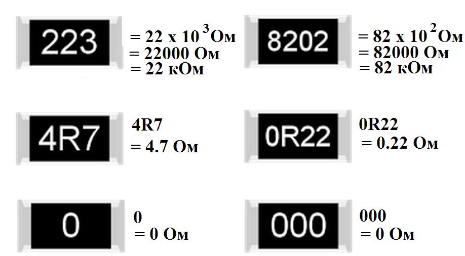
If the code has three or four digits, then the last digit means the number of zeros. In Fig. 5. resistor with code “223” has the following resistance: 22 (and three zeros to the right) Ohm = 22000 Ohm = 22 kOhm. Resistor code "8202" has a resistance of: 820 (and two zeros on the right) Ohm = 82000 Ohm = 82 kOhm.
In some cases, the marking is alphanumeric. For example, a resistor with code 4R7 has a resistance of 4.7 Ohms, and a resistor with code 0R22 has a resistance of 0.22 Ohms (here the letter R is the separator character).
There are also zero resistance resistors, or jumper resistors. They are often used as fuses.
Of course, you don’t have to remember the code system, but simply measure the resistance of the resistor with a multimeter.
Rice. 5 Marking of chip resistors
Ceramic SMD capacitors
Externally, SMD capacitors are very similar to resistors (see Fig. 6.). There is only one problem: the capacitance code is not marked on them, so the only way to determine it is to measure it with a multimeter that has a capacitance measurement mode.
SMD capacitors are also available in standard sizes, usually similar to resistor sizes (see above).

Rice. 6. Ceramic SMD capacitors
Electrolytic SMS capacitors

Fig.7. Electrolytic SMS capacitors
These capacitors are similar to their lead-out counterparts, and the markings on them are usually clear: capacitance and operating voltage. A stripe on the cap of the capacitor marks its negative terminal.
SMD transistors

Fig.8. SMD transistor
Transistors are small, so it is impossible to write their full name on them. They are limited to code markings, and there is no international standard for designations. For example, code 1E may indicate the type of transistor BC847A, or maybe some other one. But this circumstance does not bother either manufacturers or ordinary consumers of electronics at all. Difficulties can only arise during repairs. Determining the type of transistor installed on a printed circuit board without the manufacturer's documentation for this board can sometimes be very difficult.
SMD diodes and SMD LEDs
Photos of some diodes are shown in the figure below:

Fig.9. SMD diodes and SMD LEDs
The polarity must be indicated on the diode body in the form of a stripe closer to one of the edges. Usually the cathode terminal is marked with a stripe.
An SMD LED also has a polarity, which is indicated either by a dot near one of the pins, or in some other way (you can find out more about this in the documentation of the component manufacturer).
Determining the type of SMD diode or LED, as in the case of a transistor, is difficult: an uninformative code is stamped on the diode body, and most often there are no marks at all on the LED body, except for the polarity mark. Developers and manufacturers of modern electronics care little about their maintainability. It is assumed that the printed circuit board will be repaired by a service engineer who has complete documentation for a specific product. Such documentation clearly describes where on the printed circuit board a particular component is installed.
Installation and soldering of SMD components
SMD assembly is optimized primarily for automatic assembly by special industrial robots. But amateur radio designs can also be made using chip components: with sufficient care and attention, you can solder parts the size of a grain of rice with the most ordinary soldering iron, you only need to know a few subtleties.
But this is a topic for a separate large lesson, so more details about automatic and manual SMD installation will be discussed separately.
In our turbulent age of electronics, the main advantages of an electronic product are small size, reliability, ease of installation and dismantling (disassembling equipment), low energy consumption and convenient usability ( from English- Ease of use). All these advantages are by no means possible without surface mount technology - SMT technology ( S urface M ount T echnology), and of course, without SMD components.
What are SMD components
SMD components are used in absolutely all modern electronics. SMD ( S urface M mounted D evice), which translated from English means “surface-mounted device.” In our case, the surface is a printed circuit board, without through holes for radio elements:
In this case, SMD components are not inserted into the holes of the boards. They are soldered onto contact tracks, which are located directly on the surface of the printed circuit board. The photo below shows tin-colored contact pads on a mobile phone board that previously had SMD components.

Pros of SMD components
The biggest advantage of SMD components is their small size. The photo below shows simple resistors and:


Thanks to the small dimensions of SMD components, developers have the opportunity to place a larger number of components per unit area than simple output radio elements. Consequently, the installation density increases and, as a result, the dimensions of electronic devices decrease. Since the weight of an SMD component is many times lighter than the weight of the same simple output radio element, the weight of the radio equipment will also be many times lighter.

SMD components are much easier to desolder. For this we need a hairdryer. You can read how to desolder and solder SMD components in the article on how to solder SMDs correctly. It's much more difficult to seal them. In factories, special robots place them on a printed circuit board. No one solders them manually in production, except for radio amateurs and radio equipment repairmen.
Multilayer boards
Since equipment with SMD components has a very dense installation, there should be more tracks on the board. Not all tracks fit on one surface, so printed circuit boards are made multilayer. If the equipment is complex and has a lot of SMD components, then the board will have more layers. It's like a multi-layer cake made from short layers. The printed tracks connecting SMD components are located directly inside the board and cannot be seen in any way. An example of multilayer boards is mobile phone boards, computer or laptop boards (motherboard, video card, RAM, etc.).
In the photo below, the blue board is the Iphone 3g, the green board is the computer motherboard.


All radio equipment repairers know that if a multilayer board is overheated, it will swell with a bubble. In this case, the interlayer connections break and the board becomes unusable. Therefore, the main trump card when replacing SMD components is the correct temperature.
Some boards use both sides of the printed circuit board, and the mounting density, as you understand, doubles. This is another advantage of SMT technology. Oh yes, it’s also worth taking into account the fact that the material required for the production of SMD components is much less, and their cost during mass production of millions of pieces literally costs pennies.
Main types of SMD components
Let's look at the main SMD elements used in our modern devices. Resistors, capacitors, low-value inductors, and other components look like ordinary small rectangles, or rather, parallelepipeds))

On boards without a circuit, it is impossible to know whether it is a resistor, a capacitor, or even a coil. The Chinese mark as they please. On large SMD elements, they still put a code or numbers to determine their identity and value. In the photo below, these elements are marked in a red rectangle. Without a diagram, it is impossible to say what type of radio elements they belong to, as well as their rating.

The standard sizes of SMD components may be different. Here is a description of the standard sizes for resistors and capacitors. Here, for example, is a yellow rectangular SMD capacitor. They are also called tantalum or simply tantalum:

And this is what SMDs look like:


There are also these types of SMD transistors:

Which have a high denomination, in SMD version they look like this:


And of course, how could we live without microcircuits in our age of microelectronics! There are many SMD types of chip packages, but I divide them mainly into two groups:
1) Microcircuits in which the pins are parallel to the printed circuit board and are located on both sides or along the perimeter.

2) Microcircuits in which the pins are located under the microcircuit itself. This is a special class of microcircuits called BGA (from English Ball grid array- an array of balls). The terminals of such microcircuits are simple solder balls of the same size.
The photo below shows a BGA chip and its reverse side, consisting of ball pins.

BGA chips are convenient for manufacturers because they greatly save space on the printed circuit board, because there can be thousands of such balls under any BGA chip. This makes life much easier for manufacturers, but does not make life any easier for repairmen.
Summary
What should you use in your designs? If your hands don’t shake and you want to make a small radio bug, then the choice is obvious. But still, in amateur radio designs, dimensions do not play a big role, and soldering massive radio elements is much easier and more convenient. Some radio amateurs use both. Every day more and more new microcircuits and SMD components are being developed. Smaller, thinner, more reliable. The future definitely belongs to microelectronics.
In the element base of a computer (and not only) there is one bottleneck - electrolytic capacitors. They contain an electrolyte, the electrolyte is a liquid. Therefore, heating such a capacitor leads to its failure, as the electrolyte evaporates. And heating in the system unit is a regular occurrence.
Therefore, replacing capacitors is a matter of time. More than half of the failures of motherboards in the middle and lower price categories are due to dry or swollen capacitors. Even more often, computer power supplies break down for this reason.
Since the printing on modern boards is very dense, replacing capacitors must be done very carefully. You can damage and not notice a small unframed element or break (short) tracks, the thickness and distance between which is slightly greater than the thickness of a human hair. It’s quite difficult to fix something like this later. So be careful.
So, to replace capacitors you will need a soldering iron with a thin tip with a power of 25-30 W, a piece of thick guitar string or a thick needle, soldering flux or rosin.
If you reverse the polarity when replacing an electrolytic capacitor or install a capacitor with a low voltage rating, it may well explode. And here's what it looks like:

So, carefully select the replacement part and install it correctly. Electrolytic capacitors are always marked with a negative terminal (usually a vertical stripe of a different color from the body color). On the printed circuit board, the hole for the negative contact is also marked (usually with black shading or solid white). The ratings are written on the capacitor body. There are several of them: voltage, capacity, tolerances and temperature.
The first two are always present, the others may be absent. Voltage: 16V(16 volts). Capacity: 220µF(220 microfarads). These values are very important when replacing. The voltage can be chosen equal or with a higher nominal value. But the capacitance affects the charging/discharging time of the capacitor and in some cases can be important for a section of the circuit.
Therefore, the capacity should be selected equal to that indicated on the case. On the left in the photo below is a green swollen (or leaking) capacitor. In general, there are constant problems with these green capacitors. The most common candidates for replacement. On the right is a working capacitor, which we will solder.

The capacitor is soldered as follows: first find the legs of the capacitor on the back side of the board (for me this is the most difficult moment). Then heat one of the legs and lightly press the capacitor body from the side of the heated leg. When the solder melts, the capacitor tilts. Carry out a similar procedure with the second leg. Usually the capacitor is removed in two steps.
There is no need to rush, and there is no need to press too hard. The motherboard is not a double-sided PCB, but a multilayer one (imagine a wafer). Overdoing it can damage the contacts on the inner layers of the printed circuit board. So no fanaticism. By the way, long-term heating can also damage the board, for example, lead to peeling or tearing of the contact pad. Therefore, there is no need to press hard with a soldering iron either. We lean the soldering iron and press lightly on the capacitor.


After removing the damaged capacitor, it is necessary to make holes so that the new capacitor can be inserted freely or with little effort. For these purposes, I use a guitar string of the same thickness as the legs of the part being soldered. A sewing needle is also suitable for these purposes, but needles are now made of ordinary iron, and strings are made of steel. There is a chance that the needle will get caught in the solder and break when you try to pull it out. And the string is quite flexible and steel and solder adhere much worse than iron.

When removing capacitors, solder most often clogs the holes in the board. If you try to solder the capacitor in the same way that I advised you to solder it, you can damage the contact pad and the track leading to it. Not the end of the world, but a very undesirable occurrence. Therefore, if the holes are not clogged with solder, they simply need to be expanded. And if you do, then you need to press the end of the string or needle tightly to the hole, and on the other side of the board, lean the soldering iron against this hole. If this option is inconvenient, then the soldering iron tip should be leaned against the string almost at the base. When the solder melts, the string will fit into the hole. At this moment you need to rotate it so that it does not grab the solder.
After obtaining and expanding the hole, it is necessary to remove excess solder from its edges, if any, otherwise, during soldering of the capacitor, a tin cap may form, which can solder adjacent tracks in those places where the seal is dense. Pay attention to the photo below - how close the tracks are to the holes. Soldering this is very easy, but difficult to notice, since the installed capacitor interferes with the view. Therefore, it is very advisable to remove excess solder.

If you don’t have a radio market nearby, then most likely you can only find a used capacitor for replacement. Before installation, its legs should be treated, if necessary. It is advisable to remove all solder from the legs. I usually coat the legs with flux and tin them with a clean soldering iron tip, the solder collects on the soldering iron tip. Then I scrape the legs of the capacitor with a utility knife (just in case).

That's all, actually. We insert the capacitor, lubricate the legs with flux and solder. By the way, if you use pine rosin, it is better to crush it into powder and apply it to the installation site than to dip a soldering iron in a piece of rosin. Then it will work out neatly.

Replacing a capacitor without desoldering it from the board
Repair conditions vary, and changing a capacitor on a multilayer (PC motherboard, for example) printed circuit board is not the same as changing a capacitor in a power supply (single-layer, single-sided printed circuit board). You must be extremely careful and careful. Unfortunately, not everyone was born with a soldering iron in their hands, and repairing (or trying to repair) something is very necessary.
As I already wrote in the first half of the article, most often the cause of breakdowns is capacitors. Therefore, replacing capacitors is the most common type of repair, at least in my case. Specialized workshops have special equipment for these purposes. If you don’t have it, you have to use conventional equipment (flux, solder and soldering iron). In this case, experience helps a lot.
The main advantage of this method is that the contact pads of the board will have to be subjected to much less heat. At least twice. Printing on cheap motherboards quite often peels off due to heat. The tracks come off, and fixing this later is quite problematic.
The disadvantage of this method is that you still have to put pressure on the board, which can also lead to negative consequences. Although from my personal experience I have never had to press hard. In this case, there is every chance of soldering to the legs remaining after mechanical removal of the capacitor.
So, replacing a capacitor begins with removing the damaged part from the motherboard.

You need to place your finger on the capacitor and, with light pressure, try to swing it up and down and left and right. If the capacitor swings left and right, then the legs are located along the vertical axis (as in the photo), otherwise along the horizontal axis. You can also determine the position of the legs by the negative marker (a strip on the capacitor body indicating the negative contact).
Next, you should press the capacitor along the axis of its legs, but not sharply, but smoothly, slowly increasing the load. As a result, the leg is separated from the body, then we repeat the procedure for the second leg (press from the opposite side).
Sometimes the leg is pulled out along with the capacitor due to bad solder. In this case, you can slightly widen the resulting hole (I do this with a piece of guitar string) and insert a piece of copper wire there, preferably the same thickness as the leg.

Half the job is done, now we move directly to replacing the capacitor. It is worth noting that the solder does not stick well to the part of the leg that was inside the capacitor body and it is better to bite it off with wire cutters, leaving a small part. Then the legs of the capacitor prepared for replacement and the legs of the old capacitor are treated with solder and soldered. It is most convenient to solder the capacitor by placing it on the board at an angle of 45 degrees. Then you can easily stand him at attention.

The resulting appearance is, of course, unaesthetic, but it works and this method is much simpler and safer than the previous one in terms of heating the board with a soldering iron. Happy renovation!
If the site materials were useful to you, you can support the further development of the resource by supporting it (and me).


