How to make a 12V power supply. Do-it-yourself powerful switching power supply. Power supply components
Can a master do construction without such an indispensable tool as a screwdriver? It will not be possible to carry out full-fledged work without using such a tool, because you always need to tighten or strengthen something somewhere. This necessity in the household of a screwdriver is explained by its functionality and ability to significantly facilitate some of the stages of construction and finishing work.
You may not know which screwdriver is better, but you will definitely appreciate all its capabilities, especially those who have previously screwed in screws with a screwdriver. But, like any equipment, a cordless screwdriver loses its former efficiency over time and no longer works with as much power as before. How to solve such a problem if it occurs? Of course, you can purchase another battery, but the cost of a new battery is steep, so the craftsmen offer an alternative - making a 12V power supply for the screwdriver with your own hands. This is an excellent way out of the situation and a great opportunity to try your hand at radio engineering.
Stages of preliminary work: preparing for construction
Before you start remaking the battery, select another power supply unit that is suitable in size; then it must be placed in the existing case and secured. Everything is removed from the inside of the prepared device and the internal space is measured, which differs from the external contents.
What you need to know before starting construction
Study the markings or design features indicated on the body of the working tool, and, based on these indicators, determine the voltage required for power supply. In our case, it will be enough to assemble a 12V power supply for a screwdriver with your own hands. If the required ratings are other than 12V, continue to look for an interchangeable option. Having chosen an analogue, calculate the current consumption of the screwdriver, since the manufacturer does not indicate this parameter. To find out, you will need to know the power of the device.

If you don’t have time to select a device, and the calculations take too much time, take any power supply you come across. When buying it, in addition to the current, ask about the battery capacity. To construct a 12V power supply for a screwdriver with your own hands, a device with a capacity of 1.2A and a charge of 2.5 will be sufficient. Remember, before looking for recharging, determine the following necessary parameters:
- Block dimensions.
- Minimum current.
- Required voltage level.
The process of designing a battery pack for a screwdriver
Having selected a new device and all the parts necessary for design, you can begin to work. Assembling a 12V power supply for a screwdriver with your own hands consists of the following steps:
- Having selected the optimal power supply, check it for similarity with the declared characteristics, which will depend on which screwdriver. It is better to use a computer block as the basis for a new battery.
- Disassemble the screwdriver and remove the old drive. If the body is glued, gently tap along the seam with a hammer or score using a thin knife blade. This way you will open the box with the least damage.
- Unsolder the cord and leads from the plug and separate them from the rest of the structure.
- In the place where the battery power supply for the screwdriver was previously located, place the other contents removed from the case.
- Lead the power cord through the opening in the housing. Connect it to the power supply by soldering it in place.
- Use soldering to connect the output of the computer power supply to the battery terminals. Remember to maintain polarity.
- Connect the designed battery to the device and test it.
- If the dimensions of the new charger exceed those of the old battery, it can be built inside the screwdriver handle.
- To limit the supply of voltage from the network to the battery with a parallel supply output, install a diode with the required power from inside the “+” cable break between the battery socket, including the output, but with the “-” pole towards the engine.

What does this battery upgrade give?
Transforming the power supply for a computer into a battery for a screwdriver operating continuously from the mains has a number of advantages, namely:
- There is no need to worry about periodically recharging the device.
- Downtime during long periods of operation is reduced to a minimum.
- The torque remains constant thanks to the constant current supply.
- Connecting a converted computer power supply for a screwdriver (12V) does not in any way affect the technical parameters of the product, even if the device has not been used for a long period of time.
The only quality that is mentioned as a disadvantage is the presence of an electrical outlet near the work site. This problem can be easily solved by connecting an extension cord.

Materials and working tools for upgrading a screwdriver
Remaking a computer power supply for a screwdriver is not difficult; moreover, such an activity is educational, especially for beginners in the field of radio mechanics. Having the necessary skills and all the components, in a short time you will have a transformed corded screwdriver. To carry out the work you will need:
- charger from a screwdriver;
- old factory battery;
- soft multi-core electrical cable;
- soldering iron and solder;
- acids;
- insulating tape;
- power supply from a computer (or another).
Transformation options
You can use various power supply options to create a compact battery for uninterrupted operation of the screwdriver.

Battery or power supply from computer equipment
A device that supports the charge of a PC or laptop is quite suitable for achieving this goal. The process of introducing a power supply into a screwdriver is as follows:
- The screwdriver body is completely disassembled.
- The old power supply is removed and the wires are unsoldered.
- The wiring of the new unit is connected to the wiring of the old one, which powers the previous battery. When carrying out such an operation, it is important to observe polarity!
- Turn on the screwdriver and check for functionality. If all wires are connected correctly, the machine will work.
- There is a hole in the body of the device where a plug with a charging connector can easily be placed. By upgrading a screwdriver in this way, you get an improved device, which is now also recharged during operation like a laptop from a 220V network.
- The new power source is mounted inside the screwdriver, securing it with glue.
- The remaining body elements are returned to their place and the product is twisted, giving it its original appearance.
That's all! Now you know how to turn a cordless screwdriver into a corded one.

Car battery as a power source
A car battery is an excellent option for remotely connecting a screwdriver to the network. To implement the idea, simply disconnect the clamps from the working tool and connect it to a power source.
Important! The use of such a source for long-term operation of a screwdriver is highly not recommended.
Using a welding inverter to power a screwdriver
To remake the old design, prepare a power supply circuit for a 12V screwdriver. The old design is improved to some extent by adding a secondary coil.
When compared with a computer battery, the advantage of the inverter is immediately noticeable. Thanks to the design features, it is immediately possible to determine the required voltage level and output current. This is an ideal method for those who live in radio engineering.
Features of corded screwdrivers
You can transform the device into a network device using another method, based on the production of a mobile station for recharging a screwdriver. An elastic wire is connected to the unit, to one end of which a plug is attached. Although, in order to operate such a station, you will need to build a special power supply or connect a ready-made transformer with a rectifier.
Important! Do not forget to ensure that the characteristics of the transformer match the parameters of the instrument.

If you are new to this business, then most likely it will be difficult for you to transform the coil with your own hands. Without having important skills, you can make a mistake with the number of turns or selection of wire diameter, so it is better to entrust such work to a specialist or at least a person who understands the topic.
90% of equipment is sold with a built-in transformer. All you need to do is select the best option and design a rectifier for it. To solder the rectifier bridge, semiconductor diodes are used, selected strictly according to the parameters of the tool.
Experts recommend following certain rules to everyone who decides to reconstruct a screwdriver and construct a 12V power supply for a screwdriver with their own hands. Instructions for upgrading the tool include the following tips:
- You can use a corded screwdriver as much as you like without worrying about the battery running out. However, such an instrument needs rest. Therefore, take five-minute breaks to avoid overheating or overloading the instrument.
- When working with a screwdriver, do not forget to secure the wire in the elbow area. This will make it more convenient to operate the device, and the cord will not interfere when screwing in screws.
- Carry out systematic cleaning of the screwdriver power supply from accumulations of dust and dirt deposits.
- The new battery is provided with grounding.
- Do not use more than one extension cord to connect to the network.
- This device is not recommended for use in high-altitude work (from two meters).
Now you know what power supply is needed for a 12V screwdriver, and what materials to use to make such a design yourself at home. There is no need to replace the old screwdriver with a new one. A radical decision should be made only if the unit is completely out of order, and a “dead” battery is not a problem for the craftsman. You just need to have an understanding of radio engineering and arm yourself with a soldering iron. Then it will be easier to cope with the task.
The type of power supply, as already noted, is switching. This solution dramatically reduces the weight and size of the structure, but works no worse than the ordinary network transformer we are used to. The circuit is assembled on a powerful IR2153 driver. If the microcircuit is in a DIP package, then a diode must be installed. As for the diode, please note that it is not an ordinary one, but an ultra-fast one, since the operating frequency of the generator is tens of kilohertz and ordinary rectifier diodes will not work here.

In my case, the entire circuit was assembled in bulk, since I assembled it only to test its functionality. I practically didn’t need to set up the circuit and immediately started working like a Swiss watch.
Transformer— it is advisable to take a ready-made one, from a computer power supply (literally any one will do, I took a transformer with a pigtail from an ATX 350 watt power supply). At the output of the transformer, you can use a rectifier made of SCHOTTTKY diodes (can also be found in computer power supplies), or any fast and ultra-fast diodes with a current of 10 Amps or more, you can also use our KD213A.


Connect the circuit to the network through a 220 Volt 100 watt incandescent lamp; in my case, all the tests were done with a 12-220 inverter with short-circuit and overload protection, and only after fine tuning I decided to connect it to the 220 Volt network.
How should the assembled circuit work?
- The keys are cold, without an output load (even with an output load of 50 watts, my keys remained icy).
- The microcircuit should not overheat during operation.
- Each capacitor should have a voltage of about 150 Volts, although the nominal value of this voltage may deviate by 10-15 Volts.
- The circuit should operate silently.
- The microcircuit's power resistor (47k) should overheat slightly during operation; a slight overheating of the snubber resistor (100 Ohm) is also possible.
The main problems that arise after assembly
Problem 1. We assembled a circuit; when connected, the control light that is connected to the output of the transformer blinks, and the circuit itself makes strange sounds.
Solution. Most likely there is not enough voltage to power the microcircuit, try reducing the resistance of the 47k resistor to 45, if that doesn’t help, then to 40 and so on (in 2-3kOhm steps) until the circuit works normally.
Problem 2. We assembled a circuit; when power is applied, nothing heats up or explodes, but the voltage and current at the transformer output are negligible (almost zero)
Solution. Replace the 400V 1uF capacitor with a 2mH inductor.
Problem 3. One of the electrolytes gets very hot.
Solution. Most likely it is not working, replace it with a new one and at the same time check the diode rectifier, maybe it is because of the non-working rectifier that the capacitor receives a change.
The switching power supply on the ir2153 can be used to power powerful, high-quality amplifiers, or used as a charger for powerful lead batteries, or as a power supply - all at your discretion.
The power of the unit can reach up to 400 watts, for this you will need to use a 450-watt ATX transformer and replace the electrolytic capacitors with 470 µF - and that’s it!
In general, you can assemble a switching power supply with your own hands for only $10-12, and that’s if you take all the components from a radio store, but every radio amateur has more than half of the radio components used in the circuit.
Somehow recently I came across a circuit on the Internet for a very simple power supply with the ability to adjust the voltage. The voltage could be adjusted from 1 Volt to 36 Volt, depending on the output voltage on the secondary winding of the transformer.
Take a close look at the LM317T in the circuit itself! The third leg (3) of the microcircuit is connected to capacitor C1, that is, the third leg is INPUT, and the second leg (2) is connected to capacitor C2 and a 200 Ohm resistor and is an OUTPUT.
Using a transformer, from a mains voltage of 220 Volts we get 25 Volts, no more. Less is possible, no more. Then we straighten the whole thing with a diode bridge and smooth out the ripples using capacitor C1. All this is described in detail in the article on how to obtain constant voltage from alternating voltage. And here is our most important trump card in the power supply - this is a highly stable voltage regulator chip LM317T. At the time of writing, the price of this chip was around 14 rubles. Even cheaper than a loaf of white bread.
Description of the chip
LM317T is a voltage regulator. If the transformer produces up to 27-28 volts on the secondary winding, then we can easily regulate the voltage from 1.2 to 37 volts, but I would not raise the bar to more than 25 volts at the transformer output.
The microcircuit can be executed in the TO-220 package:

or in D2 Pack housing

It can pass a maximum current of 1.5 Amps, which is enough to power your electronic gadgets without voltage drop. That is, we can output a voltage of 36 Volts with a current load of up to 1.5 Amps, and at the same time our microcircuit will still output 36 Volts - this, of course, is ideal. In reality, fractions of volts will drop, which is not very critical. With a large current in the load, it is more advisable to install this microcircuit on a radiator.
In order to assemble the circuit, we also need a variable resistor of 6.8 Kilo-Ohms, or even 10 Kilo-Ohms, as well as a constant resistor of 200 Ohms, preferably from 1 Watt. Well, we put a 100 µF capacitor at the output. Absolutely simple scheme!
Assembly in hardware
Previously, I had a very bad power supply with transistors. I thought, why not remake it? Here is the result ;-)
Here we see the imported GBU606 diode bridge. It is designed for a current of up to 6 Amps, which is more than enough for our power supply, since it will deliver a maximum of 1.5 Amps to the load. I installed the LM on the radiator using KPT-8 paste to improve heat transfer. Well, everything else, I think, is familiar to you.

And here is an antediluvian transformer that gives me a voltage of 12 volts on the secondary winding.

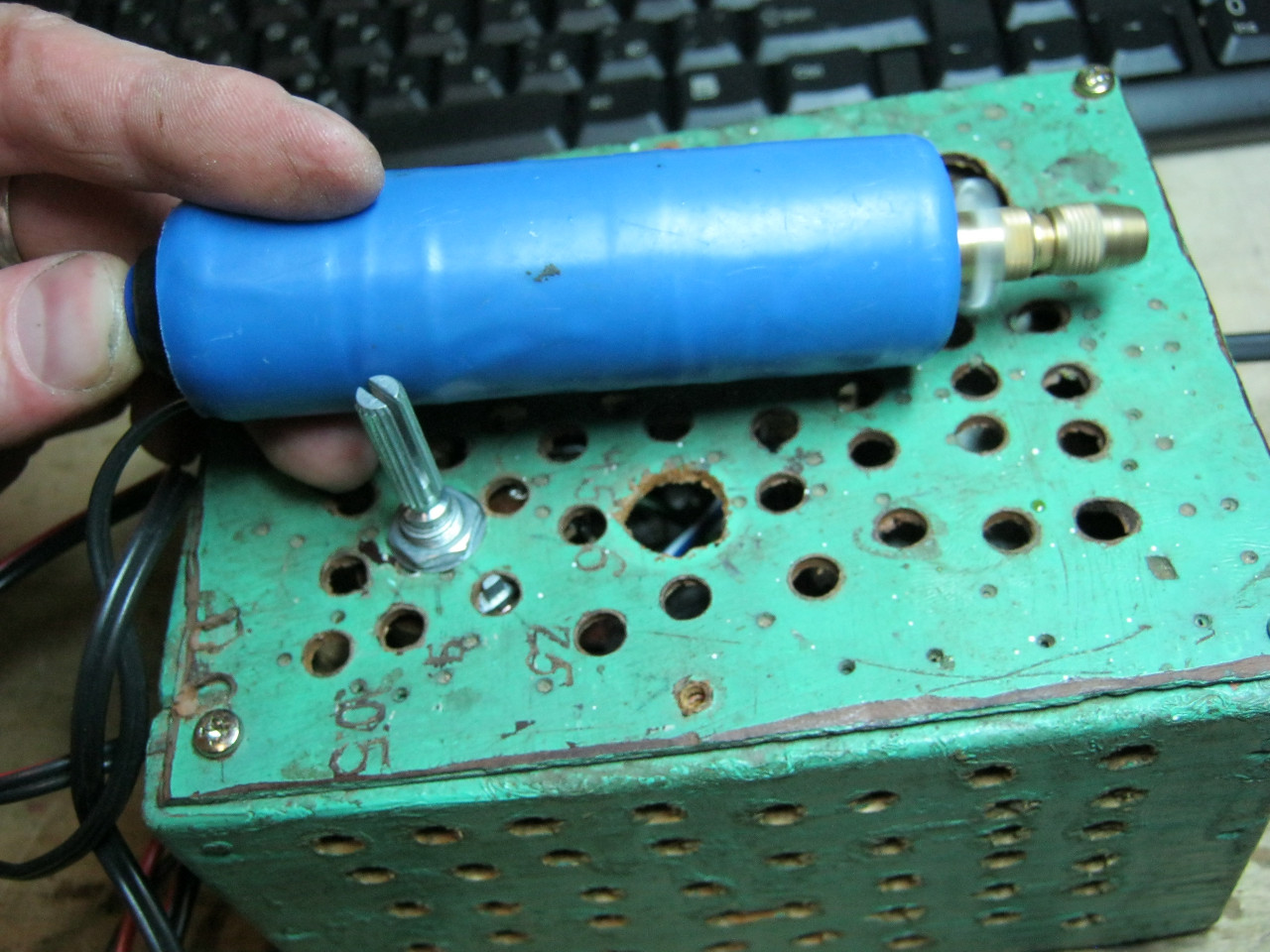
We carefully pack all this into the case and remove the wires.

So what do you think? ;-)

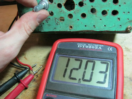
The minimum voltage I got was 1.25 Volts, and the maximum was 15 Volts.

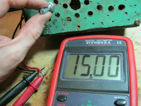
I set any voltage, in this case the most common are 12 Volts and 5 Volts

Everything works great!
This power supply is very convenient for adjusting the speed of a mini drill, which is used for drilling circuit boards.
Analogues on Aliexpress
By the way, on Ali you can immediately find a ready-made set of this block without a transformer.

Too lazy to collect? You can buy a ready-made 5 Amp for less than $2:

You can view it at this link.
If 5 Amps is not enough, then you can look at 8 Amps. It will be enough for even the most seasoned electronics engineer:

With the current level of development of the element base of radio-electronic components, a simple and reliable power supply with your own hands can be made very quickly and easily. This does not require high-level knowledge of electronics and electrical engineering. You will soon see this.
Making your first power source is quite an interesting and memorable event. Therefore, an important criterion here is the simplicity of the circuit, so that after assembly it immediately works without any additional settings or adjustments.
It should be noted that almost every electronic, electrical device or appliance needs power. The difference lies only in the basic parameters - the magnitude of voltage and current, the product of which gives power.
Making a power supply with your own hands is a very good first experience for novice electronics engineers, since it allows you to feel (not on yourself) the different magnitudes of currents flowing in devices.
The modern power supply market is divided into two categories: transformer-based and transformerless. The first ones are quite easy to manufacture for beginner radio amateurs. The second indisputable advantage is the relatively low level of electromagnetic radiation, and therefore interference. A significant drawback by modern standards is the significant weight and dimensions caused by the presence of a transformer - the heaviest and most bulky element in the circuit.
Transformerless power supplies do not have the last drawback due to the absence of a transformer. Or rather, it is there, but not in the classical presentation, but works with high-frequency voltage, which makes it possible to reduce the number of turns and the size of the magnetic circuit. As a result, the overall dimensions of the transformer are reduced. The high frequency is generated by semiconductor switches, in the process of switching on and off according to a given algorithm. As a result, strong electromagnetic interference occurs, so such sources must be shielded.
We will be assembling a transformer power supply that will never lose its relevance, since it is still used in high-end audio equipment, thanks to the minimal level of noise generated, which is very important for obtaining high-quality sound.
Design and principle of operation of the power supply
The desire to obtain a finished device as compact as possible led to the emergence of various microcircuits, inside of which there are hundreds, thousands and millions of individual electronic elements. Therefore, almost any electronic device contains a microcircuit, the standard power supply of which is 3.3 V or 5 V. Auxiliary elements can be powered from 9 V to 12 V DC. However, we know well that the outlet has an alternating voltage of 220 V with a frequency of 50 Hz. If it is applied directly to a microcircuit or any other low-voltage element, they will instantly fail.

From here it becomes clear that the main task of the mains power supply (PSU) is to reduce the voltage to an acceptable level, as well as convert (rectify) it from AC to DC. In addition, its level must remain constant regardless of fluctuations in the input (in the socket). Otherwise, the device will be unstable. Therefore, another important function of the power supply is voltage level stabilization.
In general, the structure of the power supply consists of a transformer, rectifier, filter and stabilizer.
In addition to the main components, a number of auxiliary components are also used, for example, indicator LEDs that signal the presence of supplied voltage. And if the power supply provides for its adjustment, then naturally there will be a voltmeter, and possibly also an ammeter.
Transformer
In this circuit, a transformer is used to reduce the voltage in a 220 V outlet to the required level, most often 5 V, 9 V, 12 V or 15 V. At the same time, galvanic isolation of high-voltage and low-voltage circuits is also carried out. Therefore, in any emergency situations, the voltage on the electronic device will not exceed the value of the secondary winding. Galvanic isolation also increases the safety of operating personnel. In case of touching the device, a person will not fall under the high potential of 220 V.
The design of the transformer is quite simple. It consists of a core that performs the function of a magnetic circuit, which is made of thin plates that conduct magnetic flux well, separated by a dielectric, which is a non-conductive varnish.
At least two windings are wound on the core rod. One is primary (also called network) - 220 V is supplied to it, and the second is secondary - reduced voltage is removed from it.

The operating principle of the transformer is as follows. If voltage is applied to the mains winding, then, since it is closed, alternating current will begin to flow through it. Around this current, an alternating magnetic field arises, which collects in the core and flows through it in the form of a magnetic flux. Since there is another winding on the core - the secondary one, under the influence of an alternating magnetic flux an electromotive force (EMF) is generated in it. When this winding is shorted to a load, alternating current will flow through it.
Radio amateurs in their practice most often use two types of transformers, which mainly differ in the type of core - armored and toroidal. The latter is more convenient to use in that it is quite easy to wind the required number of turns onto it, thereby obtaining the required secondary voltage, which is directly proportional to the number of turns.
![]()
The main parameters for us are two parameters of the transformer - voltage and current of the secondary winding. We will take the current value to be 1 A, since we will use zener diodes for the same value. About that a little further.
We continue to assemble the power supply with our own hands. And the next order element in the circuit is a diode bridge, also known as a semiconductor or diode rectifier. It is designed to convert the alternating voltage of the secondary winding of the transformer into direct voltage, or more precisely, into rectified pulsating voltage. This is where the name “rectifier” comes from.
There are various rectification circuits, but the bridge circuit is the most widely used. The principle of its operation is as follows. In the first half-cycle of the alternating voltage, current flows along the path through the diode VD1, resistor R1 and LED VD5. Next, the current returns to the winding through open VD2.

A reverse voltage is applied to the diodes VD3 and VD4 at this moment, so they are locked and no current flows through them (in fact, it only flows at the moment of switching, but this can be neglected).
In the next half-cycle, when the current in the secondary winding changes its direction, the opposite will happen: VD1 and VD2 will close, and VD3 and VD4 will open. In this case, the direction of current flow through resistor R1 and LED VD5 will remain the same.

A diode bridge can be soldered from four diodes connected according to the diagram above. Or you can buy it ready-made. They come in horizontal and vertical versions in different housings. But in any case, they have four conclusions. The two terminals are supplied with alternating voltage, they are designated by the sign “~”, both are the same length and are the shortest.

The rectified voltage is removed from the other two terminals. They are designated “+” and “-”. The “+” pin has the longest length among the others. And on some buildings there is a bevel near it.
Capacitor filter
After the diode bridge, the voltage has a pulsating nature and is still unsuitable for powering microcircuits, and especially microcontrollers, which are very sensitive to various kinds of voltage drops. Therefore it needs to be smoothed out. To do this, you can use a choke or a capacitor. In the circuit under consideration, it is enough to use a capacitor. However, it must have a large capacitance, so an electrolytic capacitor should be used. Such capacitors often have polarity, so it must be observed when connecting to the circuit.

The negative terminal is shorter than the positive one and a “-” sign is applied to the body near the first one.

Voltage regulator L.M. 7805, L.M. 7809, L.M. 7812
You probably noticed that the voltage in the outlet is not equal to 220 V, but varies within certain limits. This is especially noticeable when connecting a powerful load. If you do not apply special measures, then it will change in a proportional range at the output of the power supply. However, such vibrations are extremely undesirable and sometimes unacceptable for many electronic elements. Therefore, the voltage after the capacitor filter must be stabilized. Depending on the parameters of the powered device, two stabilization options are used. In the first case, a zener diode is used, and in the second, an integrated voltage stabilizer is used. Let's consider the application of the latter.
In amateur radio practice, voltage stabilizers of the LM78xx and LM79xx series are widely used. Two letters indicate the manufacturer. Therefore, instead of LM there may be other letters, for example CM. The marking consists of four numbers. The first two - 78 or 79 - mean positive or negative voltage, respectively. The last two digits, in this case instead of two X's: xx, indicate the value of the output U. For example, if the position of two X's is 12, then this stabilizer produces 12 V; 08 – 8 V, etc.
For example, let's decipher the following markings:
LM7805 → 5V positive voltage
LM7912 → 12 V negative U

Integrated stabilizers have three outputs: input, common and output; designed for current 1A.

If the output U significantly exceeds the input and the maximum current consumption is 1 A, then the stabilizer gets very hot, so it should be installed on a radiator. The design of the case provides for this possibility.
If the load current is much lower than the limit, then you don’t have to install a radiator.
The classic design of the power supply circuit includes: a network transformer, a diode bridge, a capacitor filter, a stabilizer and an LED. The latter acts as an indicator and is connected through a current-limiting resistor.

Since in this circuit the current-limiting element is the LM7805 stabilizer (allowable value 1 A), all other components must be rated for a current of at least 1 A. Therefore, the secondary winding of the transformer is selected for a current of one ampere. Its voltage should not be lower than the stabilized value. And for good reason, it should be chosen from such considerations that after rectification and smoothing, U should be 2 - 3 V higher than the stabilized one, i.e. A couple of volts more than its output value should be supplied to the input of the stabilizer. Otherwise it will not work correctly. For example, for LM7805 input U = 7 - 8 V; for LM7805 → 15 V. However, it should be taken into account that if the value of U is too high, the microcircuit will heat up very much, since the “excess” voltage is extinguished at its internal resistance.
The diode bridge can be made from 1N4007 type diodes, or take a ready-made one for a current of at least 1 A.
Smoothing capacitor C1 should have a large capacity of 100 - 1000 µF and U = 16 V.
Capacitors C2 and C3 are designed to smooth out high-frequency ripple that occurs when the LM7805 operates. They are installed for greater reliability and are recommendations from manufacturers of stabilizers of similar types. The circuit also works normally without such capacitors, but since they cost practically nothing, it is better to install them.
DIY power supply for 78 L 05, 78 L 12, 79 L 05, 79 L 08
Often it is necessary to power only one or a pair of microcircuits or low-power transistors. In this case, it is not rational to use a powerful power supply. Therefore, the best option would be to use stabilizers of the 78L05, 78L12, 79L05, 79L08, etc. series. They are designed for a maximum current of 100 mA = 0.1 A, but are very compact and no larger in size than a regular transistor, and also do not require installation on a radiator.

The markings and connection diagram are similar to the LM series discussed above, only the location of the pins differs.

For example, the connection diagram for the 78L05 stabilizer is shown. It is also suitable for LM7805.

The connection diagram for negative voltage stabilizers is shown below. The input is -8 V, and the output is -5 V.

As you can see, making a power supply with your own hands is very simple. Any voltage can be obtained by installing an appropriate stabilizer. You should also remember the transformer parameters. Next we will look at how to make a power supply with voltage regulation.

So the next device has been assembled, now the question arises: what to power it from? Batteries? Batteries? No! The power supply is what we will talk about.
Its circuit is very simple and reliable, it has short-circuit protection and smooth adjustment of the output voltage.
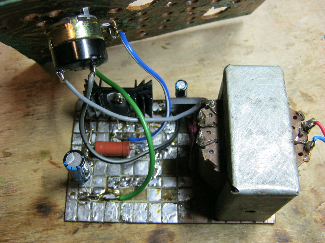
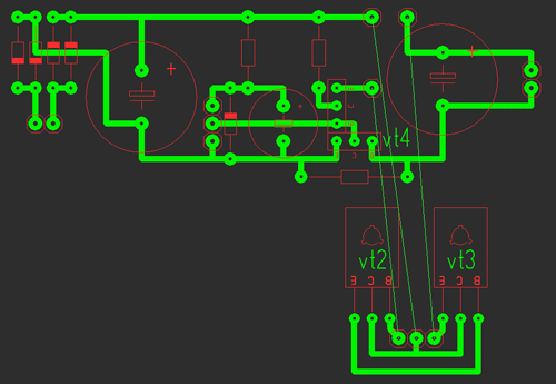
A rectifier is assembled on the diode bridge and capacitor C2, circuit C1 VD1 R3 is a reference voltage stabilizer, circuit R4 VT1 VT2 is a current amplifier for power transistor VT3, protection is assembled on transistor VT4 and R2, and resistor R1 is used for adjustment.
I took the transformer from an old charger from a screwdriver, at the output I got 16V 2A
As for the diode bridge (at least 3 amperes), I took it from an old ATX block as well as electrolytes, a zener diode, and resistors.
I used a 13V zener diode, but the Soviet D814D is also suitable.
The transistors were taken from an old Soviet TV; transistors VT2, VT3 can be replaced with one component, for example KT827.
Resistor R2 is a wirewound with a power of 7 Watts and R1 (variable) I took nichrome for adjustment without jumps, but in its absence you can use a regular one.
It consists of two parts: the first one contains the stabilizer and protection, and the second one contains the power part.
All parts are mounted on the main board (except for power transistors), transistors VT2, VT3 are soldered onto the second board, we attach them to the radiator using thermal paste, there is no need to insulate the housing (collectors). The circuit was repeated many times and does not need adjustment. Photos of two blocks are shown below with a large 2A radiator and a small 0.6A.

Indication
Voltmeter: for it we need a 10k resistor and a 4.7k variable resistor and I took an indicator m68501, but you can use another one. From resistors we will assemble a divider, a 10k resistor will prevent the head from burning out, and with a 4.7k resistor we will set the maximum deviation of the needle.
After the divider is assembled and the indication is working, you need to calibrate it; to do this, open the indicator and glue clean paper onto the old scale and cut it along the contour; it is most convenient to cut the paper with a blade.

When everything is glued and dry, we connect the multimeter in parallel to our indicator, and all this to the power supply, mark 0 and increase the voltage to volts, mark, etc.
Ammeter: for it we take a resistor of 0.27 oma!!! and variable at 50k, The connection diagram is below, using a 50k resistor we will set the maximum deviation of the arrow.
The graduation is the same, only the connection changes, see below; a 12 V halogen light bulb is ideal as a load.
List of radioelements
| Designation | Type | Denomination | Quantity | Note | Shop | My notepad |
|---|---|---|---|---|---|---|
| VT1 | Bipolar transistor | KT315B | 1 | To notepad | ||
| VT2, VT4 | Bipolar transistor | KT815B | 2 | To notepad | ||
| VT3 | Bipolar transistor | KT805BM | 1 | To notepad | ||
| VD1 | Zener diode | D814D | 1 | To notepad | ||
| VDS1 | Diode bridge | 1 | To notepad | |||
| C1 | 100uF 25V | 1 | To notepad | |||
| C2, C4 | Electrolytic capacitor | 2200uF 25V | 2 | To notepad | ||
| R2 | Resistor | 0.45 Ohm | 1 | To notepad | ||
| R3 | Resistor | 1 kOhm | 1 | To notepad | ||
| R4 | Resistor |


