What is the name of the plug on the internet cable? How to crimp a network cable and connect a computer to a computer
Twisted pair crimp circuit. What is it and what is it eaten with?
Twisted pair is a special cable consisting of four pairs of copper wires twisted together.
Thanks to this design, it is possible to significantly reduce the impact of all kinds of interference.
Cables are widely used in - this method of transmitting and receiving information deservedly remains the most reliable, fast and convenient.
Crimping twisted pair
By crimping a twisted pair cable we mean the procedure of securing special connectors located at the end of the cord.
The connectors are usually 8-pin 8P8C connectors, known to most of us as RJ-45. Connectors can be of two types:
- unshielded – designed for UTP wire;
- shielded – for cables or STP.
You need to be very careful when choosing a connector; some of them are used only by professionals, because their installation requires knowledge, experience and dexterity.
Note! It is better not to buy connectors together with an insert - their purpose is designed specifically for soft and, in particular, multi-core wires, and using them to secure a solid copper cable is very inconvenient.
It is not difficult to figure out the connector yourself; its design is quite simple and understandable - inside the device there are 8 grooves (for each copper core of the cord), at the top of which there are metal contacts.
To correctly determine the numbering of the contacts, you need to rotate the connector so that the contacts are located at the top, with the latch facing you.
In this case, the input connector will be located opposite. In this position, contact No. 1 will be on the right, and No. 8, respectively, on the left.
Numbering is important information when performing the crimping procedure.
Therefore, be sure to remember how to correctly determine, this will help to properly secure the wire and establish the connection.
There are a couple of distribution schemes: EIA/TIA-568A and EIA/TIA-568B. The difference between the circuits lies in the location of the cores.
Since all four pairs of cores twisted inside the cord have insulation of different colors, everyone can repeat the connection diagram on their own.

Important! We always start laying from the first contact to the eighth.
Color arrangement of cores in circuit 568A:
- white-green;
- green;
- white-orange;
- blue;
- white-blue;
- orange;
- white-brown;
- brown.
Twisted pair crimp circuit 568A is used to connect computers to each other when creating a local network.
Color arrangement of cores in the 568V circuit:
- white-orange;
- orange;
- white-green;
- blue;
- white-blue;
- green;
- white-brown;
- brown.
This table is useful if you need to establish a connection between the router and the computer.

Crimping methods
Network cables designed to connect computers and different types of network equipment to each other use two cable crimping options - crossover and straight.
Straight cord crimping is used in the manufacture of a cable that will serve to connect different types of network equipment and client devices to a computer, as well as to connect network equipment with each other.
This crimping method is the most common and frequently used.
The cross crimping method is used in the manufacture of wires intended for interconnection.
In this case, no additional equipment is involved in the switching.
Less commonly, a crossover cord is used to connect old ones into a network through up-link ports.
To make a straight type, you can use any crimping scheme, the main condition is that both ends of the cable are crimped identically.
Most often, when creating a direct power cord, the 568V circuit is used.

Sometimes, to make a straight type, you can use not four twisted pairs, but only two.
Using such a cable, you can connect two pieces of computer equipment to the network.
This method of crimping a twisted pair into RJ-45 is used if there is no high local traffic in the plans; the data exchange rate will be equal to 100 Mbit/s.

For example, the rj45 pinout diagram is shown, in which green and orange are involved. For a different type of crimp, brown replaces orange, and blue replaces green.
But the instructions for connecting contacts remain unchanged.
If you need to make a crossover cable, one end is 568A, and the other is 568B.

In the manufacture of such a cable, all eight copper cores are certainly involved.
If you need to make a crossover that will provide data exchange speeds between computers up to 1000 Mbit/s, use a special crimping method.

One end will be crimped according to the example of the 568V circuit, and the other end has an rj45 pinout by color:
- white-green;
- green;
- white-orange;
- white-brown;
- brown;
- orange;
- blue;
- white and blue.
This crimping scheme differs from the 568A we have already considered - brown and blue pairs mutually replaced each other, maintaining the general sequence.
If both ends of the cable are clamped according to the 568V circuit, we get a straight network cable that is suitable for connecting a PC to a switch.
If one end of the cable is crimped according to the 568B circuit, and the other - according to the 568A circuit, we have a crossover cable suitable for connecting computers.
If you need to make a gigabit crossover cable, you should use a special crimping scheme.
How to crimp a cable for a router that is connected with one connector to the PC and the other to the LAN port? If you read this review, you will understand how simple everything really is. According to the standard, there are two options for crimping the cable, but now only one is used (the simplest). And for networks operating according to the “100Mbit/s” (100Base-T) standard, you can generally crimp not 8 wires, but 4. Examples are presented in the pictures, and there should be no problems with understanding.
It was said that there are two different standards, that is, two methods for crimping power cords. Now one of them is relevant, which is called “direct”. A cable that complies with this standard is called a “patch cord” (there is also a “crossover”, but we do not consider this option). The name speaks for itself, straight is “simple” or “regular”, where the right and left plugs are crimped equally:
Direct crimp method, patch cord
Note that the color of the insulation does not matter - it is enough that the sequence on the first and second plugs does not differ.
Typical mistakes made by installers
Let's see how a properly crimped LAN cable plug looks up close:

Pinout of the patch cord cable connector
Here all the wires are divided into pairs (first – fourth), and the mating plug will look similar. What color the wires of the first pair, the second, and so on will end up being is not important if we are talking about a separate cable. The main thing is that all pairs on the two plugs are in the same order. You cannot change the order within each pair.
Any patch cord includes three parts: a power cord, a first and a second plug. When buying plastic connectors, that is, RJ-45 plugs, choose a part with eight tracks (sometimes there are 6 tracks):

RJ-45 and telephone connector
The RJ-45 standard provides for the presence of eight wires and contacts, and 6 contacts contain another connector (telephone). Externally, these connectors are very similar.
Divide the number of wires in half
Everything discussed above is related to the “1 Gbit/s” (1000Base-T) standard. If you need a 100-megabit local network, you can safely crimp 4 wires instead of eight. The first and second pair are used:

Pinout of the “100 Mbit/s” connector
Both plugs should look the same when viewed from below - as in the picture. Actually, we only eliminated 4 “extra” conductors, but nothing else changes compared to the “1 Gbit/s” patch cord.
The RJ-45 connector looks like this in real life:

RJ-45 plug with contacts
If the connector is positioned with the top side facing you (and the bottom side towards the table), and then the contacts are directed upward, then the numbering of the wires will go from left to right. Summarizing all the information, we can say that the plugs of a 100 Mbit patch cord should look like this:
See how simple it is?
Now let's talk about what is best to use as a cable. We forgot to say that, in general, connectors can be shielded or without a shield, so the former must be used in conjunction with a shielded cable:

RJ-45 + screen, without screen
The classification of twisted pairs looks like this:
- UTP-2 – 4 conductors twisted into 2 pairs
- UTP-4 – 8 conductors (4 pairs)
- FTP-4 – 8 conductors (4 pairs) + common foil shield
- STP-4 – 8 conductors (4 pairs, each in a separate shield).
Everything else is not suitable for our purposes, and if you still decide to use a shielded cord, take care of purchasing suitable plugs. The “screen” usually has to be soldered, and patch cords, even with an FTP cable, are rare in practice. Here everything looks logical: if the distance does not exceed twenty meters, you don’t need any “screen” in principle.
Crimp the RJ-45 plug yourself
The essence of the concept of “crimping” is very simple - we forcefully drive the insulated conductor into the connector, and then clamp this conductor with the contact teeth:

How to crimp an RJ-45 connector
When preparing the cable, consider the following requirements:
- At the first step, the length of the conductors protruding from the general insulation should be 25-30 mm.
- Having placed all the wiring on the same plane, they are shortened using side cutters (the length of the protruding part should be 13-14 mm).
- The insulating tube must fit under the flat clamp, so that the protruding part of the wires does not need to be made too long.
We hope that, guided by the tips given here, you will be able to crimp the connector the first time. In fact, professionals use a special tool (crimper), but if they don’t have one, they make do with a knife and a screwdriver.
The most difficult thing when performing the operation discussed here is to remove the outer insulating layer without touching the conductors themselves.
Interestingly, most so-called “crimpers” do not provide anything for working with external insulation. So, no one canceled the requirement for “straightness of hands”. Well, the “crimper” is needed so that after pressing the contacts they remain at the same level. This requirement can be fulfilled using a flat screwdriver (especially if you need to crimp 4 conductors). The proof of this statement is presented in the video.
We looked at Ethernet standards, which involve the use of 4 or 8 cores in a cable. There is another standard referred to as 10Base-2, which refers to the connection of a coaxial cord with one central core. 10 Mbit/s is not enough, but you can screw a special connector onto a coaxial cable (or twist it) using just pliers. Probably, few people now remember about Ethernet standard 10Base-2. Since all routers have RJ-45 sockets installed, this means that you will have to keep up with the times and learn how to crimp an 8-core patch cord. Happy routing!
Crimping all wires with a screwdriver
Most often, the installation and connection of an Internet outlet related to low-current lines is carried out in a triple block:
- regular 220 Volt
- internet socket
- television under TV

For most models, for example from Schneider Electric (Unica series), Legrand, Lezard, the installation principle is almost the same and does not contain fundamental differences.
Let's take a step-by-step look at the entire cycle of connecting an Internet outlet.
Internet cable
Installation begins with installing the router in a low-current switchboard and connecting it to a 220V power outlet. 
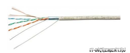
Next, a 4-pair UTP cable of the 5E series is laid in a separate cable channel or groove, not connected to power lines. 
This cable provides connection speeds of up to 1 Gigabit per second over a distance of up to 100m. Here are its technical characteristics: 
There are shielded and unshielded varieties. Foil acts as a shield in networks where there is normal grounding. 
One such 5E cable (4 pairs) can only connect two sockets. In this case, 2 pairs will be involved separately.
Installation is carried out with a single wire directly from the switchboard to the socket box. Lead the cable into the installation box and leave the necessary margin - from 15 cm or more. 
Installation of an internet outlet
First remove the cover from the socket and pull out the caliper for ease of installation. 
If the design of the socket allows, the frame can be mounted initially on the socket box. Thanks to the grooves in the frame, you can easily adjust its horizontal position.
Use 3*25mm screws to pre-tighten the entire structure. At the same time, you check the accuracy of the installation with a Pocket Electric level and tighten the screws completely.
Manufacturers have recently begun to make frames from aluminum alloy; they are, of course, stronger in design, but will not be magnetic to the level. You will have to support it with one hand. 
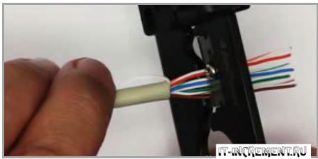
Next, bite off and leave a supply of wire in the socket, a maximum length of 15 cm. Remove the top layer of insulation from the UTP cable. 
To remove the insulation, so as not to damage the conductors, it is better to use a special tool - a stripper. But you can do all this carefully and with an ordinary stationery knife.
The top layer of the cable must be cleared to a length of no more than 2.5 cm. Cut off the excess thread in this case that goes between the cores. 
A strong thread in twisted pair cables, often used to facilitate opening the sheath over long lengths. It’s even called that – a breaking thread. In telephone cables, it separates bundles and layers.
Lightly unravel the veins individually. Next, pull out the inner part of the socket with the contacts. 
As a rule, any brand, be it a TV, an Internet outlet or a regular 220 Volt, should come with instructions.
Instructions for the Schneider Electric Unica internet socket –
Instructions for Legrand –
Standards and connection diagram
 Open the cover of the contact part and carefully study the markings. Each RJ45 socket can be connected in two ways:
- according to standard “A”
- according to standard “B”
 In most cases, the second option is used - "B". To understand where to connect which wires, carefully inspect the housing. It should indicate which standard corresponds to certain contacts.
For example on Unica:
- protocol “B” refers to the top color coding. When connecting, you will be guided by these colors.
- “A” – to the bottom color marking

If you figure this out, then there will be no difficulties with further installation. Protocol “B” follows the color scheme according to the EIA/TIA-568B standard. One side of the clip should have the following colors:
- white- orange
- orange
- white- green
- green
On the other side:
- blue
- white- blue
- white- brown
- brown
Pass the wire through the cap. In this case, as mentioned above, the top layer of UTP cable insulation should not be removed by more than 2.5 cm.
You cannot strip it right up to the wall of the socket box, as is done with conventional NYM or VVGnG cables. 
The section without insulation must be of a minimum length. All these twists are not done easily. Their exact quantity per 1 meter of cable is strictly calculated and regulated.
Otherwise, if you connect and strip it incorrectly, not only the speed, but also the quality of data transfer may decrease. 
Next, insert all the wires into the contact grooves by color. 
Then you simply snap the lid on. Extra sections of cores that protrude outwards You need to cut it off after closing the lid.
The outlet is actually already connected. All that remains is to insert it into place in the caliper.
The main advantage of such Internet sockets is that with them there is no need to remove the insulation from the cores and expose it to copper. Special knives are already installed inside the socket itself.
When you close the lid, the blades automatically cut through the insulation and create a contact connection. The instructions for such brands often indicate that when connecting the wire, the use of special crimpers is prohibited.
It’s as if it’s already in the design. That is, when the lid is closed, it itself cuts off the insulation and lays the wires to the required depth of the connector.
Connecting to the router and crimping the connector
 After installing the Internet outlet itself, all that remains is to correctly connect the cable to the router in the communication panel.
Remove the insulation from the other end of the cable by 2-3 cm. The wires are fluffed up and inserted in a certain order, according to the TIA-568B standard, or simply “B”. 
The arrangement of colors is considered from left to right:
- white- orange
- orange
- white- green
- blue
- white- blue
- green
- white- brown
- brown

Standard "A" is sometimes used if you need to connect one computer to another. Here you crimp one end of the cable according to standard “B”, and the other according to “A”. In general, if both ends of the cable are crimped to the same standard (AA or BB), then this is called a patch cord. And if they are swapped (AB or BA), then it is a cross.
Again, there is no need to strip the veins. Just insert them into the connector until it stops. 
After which all this is pressed in with a special crimper. Some people do this with a thin screwdriver or a knife blade, although this can easily damage the connector.
The cat5E and cat6 cables in the RJ45 connector are crimped according to the same principle. Another "fork" is not required here. Cables differ in data transfer speed; cat6 has a higher speed.
Checking your Internet connection
After installing the Internet socket and connector at the other end of the cable, it is advisable to check the connection and integrity of all connections. This can be done with the cheapest Chinese device. 
What is its essence? There is a signal generator that sends pulses according to certain codes, and a receiver. The generator is connected to the location where the router is installed, and the receiver is connected directly to the outlet itself.
After the pulses are applied, the signals are compared. If everything is in order, the green LED lights on the receiver body light up one by one. If there is a break or short circuit somewhere, then one or more light bulbs will not light up at all. 
When this happens, the first thing to blame is poor contact in the connectors. Most often, it is there, on any core, that the insulation is not completely cut off and, accordingly, there will be no connection.
At the very end, a ready-made, tested cable with a connector is connected to the router. 
A complete set of all tools for cutting, crimping, and testing UTP Internet cables can be ordered on AliExpress (free delivery).
How to connect a 4-wire telephone cable
 But what should you do if you use a 4-wire telephone cable for the Internet, and the socket is a standard 8-wire socket? How to connect the circuit in this case?
Simple color matching won't help here. That is, if you insert the white-blue core into contact with the white-blue marking and connect all the other wires in the same color, there will be no signal.
This is explained by the fact that to transmit the signal you need to use contacts 1-2-3-6.
On one side, connect two wires to contacts 1-2:
blue vein

In this case, everything should work without problems. Just remember that here the most important thing is not the colors, but the positions. Colors are used to make it visually easier to distinguish the positions of the same core at different ends of the cable.
Also keep in mind that when using 4 wires, i.e. two pairs of twisted pair, you can achieve speeds of up to 100Mbps. But for a gigabit network (1Gbit/sec) you will already need all 8 wires.
Errors when connecting an Internet outlet
1 Incorrect connection of cores according to the protocol.You can easily confuse the order of the wires on the connector and in the socket itself. Roughly speaking, turn them 180 degrees. 
Here everything is checked by a more careful study of the inscriptions on the body of the socket and the color of the wires themselves. A tester with a signal generator and receiver is a good helper for identifying such errors.
If the wires are connected incorrectly, the lights on the tester will light up not in order from 1 to 8, but in random patterns. For example, first 1, then immediately 3, then 2, etc. 
 That is, immediately after placing them in their places in the slot. In this case, the core may accidentally fall out, and it will not be possible to insert it back after being cut. You will have to clean everything out again and go through the entire connection cycle again.
And if you left the supply of cable in the installation box small, then you will face a big headache.
As mentioned earlier, the result here is a deterioration in the speed and quality of the signal. Moreover, there is no need to first unravel the twisted pairs to the point where the insulation is cut, especially with a screwdriver. Simply embroider them by spreading the strands to the required length to fit them into the slots. 
According to the standard, it is not allowed to unwind a twisted pair cable by more than 13mm, otherwise crosstalk errors will appear in frequency response tests. In practice, problems will begin when the network is loaded with traffic.
Categories of twisted pairs (Cat) for protection and connection
Before opening up the question, how to crimp twisted pair, I want to shed a little light on what network cables are. We encounter twisted pair cables in two situations:
- Network cable from the Internet provider laid into the apartment
- Twisted pair cable that comes with any router to connect it to a computer
Today, in the world of high Internet speeds, in order to maximize the full potential of the router and other network devices, it is extremely important that the patch cord meets a high class of protection. A technology in which information is transmitted through wires in the form of electrical impulses, highly susceptible to the influence of the surrounding electromagnetic field.
By the way, the name “twisted pair” appeared due to the design of the cable - inside it, under the braid, there are several pairs of wires - usually 4 or 8 - twisted together in twos.
The cheapest network cables (UTP) have a thin braid, inside which twisted pairs of wires are laid without any additional content. I would not recommend using such a cable even for the most trivial connection of a computer to a router.
But more often you come across Ethernet cables with shielding - additional protection laid under the braid in the form of some kind of foil to protect against extraneous interference. This category of twisted pair cable is quite suitable for solving most everyday problems for connecting to a router.
If the distance between devices is large - for example, you need to connect a local network cable to an IP surveillance camera located far away on the street, and therefore the twisted pair cable passes through many rooms with different electromagnetic backgrounds, you need to use the most protected cable to reduce losses in data transmission.
- Twisted pair UTP (Unshielded Twisted Pair) is the first, most budget option when the cable is not equipped with any protection at all.
- FTP (Foiled Twisted Pair) - this is the type that I cited as the second - the network cable has one common protective layer of foil for all, which is laid immediately under the braid.
- S/FTP or SSTP (Screened Foiled Twisted Pair) is a foil-shielded twisted pair that has protection for each group of wires plus the same external shield.
- U/STP (Unshielded Screened Twisted Pair - there is no external protection here, but each pair has its own foil protection.
- STP (Shielded Twisted Pair) - a twisted cable in this category has a separate foil shield for each pair and external protection made of fine wire mesh.
- SF/UTP or SFTP (Screened Foiled Unshielded Twisted Pair) is the most secure category in which the shielded twisted pair has as many as two external shields - one in the form of a copper mesh and the second made of foil. A drain wire is also laid between them.
According to their purpose, twisted pairs are divided into 10 main categories. I will not list everything here, but will focus only on those that are suitable for use as an Internet network cable.
- Cat 5D is a twisted pair cable consisting of 4 strands, that is, 8 cores. This cable supports data transfer rates of up to 100 Mbit/s when using two pairs and 1000 Mbit/s when using four.
- Cat 5E is an improved version of the previous category - it is thinner and cheaper. The most common option for working with Fast and Gigabit Ethernet networks.
- Cat 6E is the second most popular type of Ethernet network cable. It is unshielded, has 8 pairs of cores and supports data transfer at speeds up to 10 Gbit/s. Maximum distance - 55 meters
- Cat 6A is a network cable consisting of 4 twisted pairs. Shielding type - S/FTP or F/FTP, distance is already 200 meters
- Cat 7F - 8 cores, shielded according to the S/FTP category, the speed is the same - up to 10 Gbit/s
- 7A is the most advanced network cable, having 8 wires in its arsenal, shielded according to the S/FTP type. Information transfer occurs at speeds of up to 40 Gbit/s over a line up to 50 meters long and up to 100 Gbit/s with a maximum distance of 15 meters.
Twisted Pair Crimping Tools
Surely many have encountered such a situation when the “plug” of the Internet cable became dirty during operation, broke (this especially often happens with a plastic latch) - in general, the contacts came off and the Internet did not work well. The solution is simple: you just have to re-crimp the network cable.
For this we need:
Schemes for crimping a twisted pair internet cable
We start with the fact that before crimping the twisted pair, we need to bite off and save the old connector - it will serve as an example for us in the future. And, of course, carefully, without damaging the “twisted pairs,” clean the insulation from the end of the new cable. To do this, you can use a special double knife on purchased pliers or simply open and clean the insulation with a penknife. In front of you will be 4 twisted pairs of colored wires. It is necessary to disconnect them from each other and bite them evenly so that they are all the same length.

Next we need to decide what pattern we will use to crimp the cable. And there are two of them. The most reliable way is to look at how it was crimped before - on the bitten off connector. If you are crimping a twisted pair from scratch, you will have to think about it.
Direct type of crimping - suitable specifically for the case of crimping an Internet network cable in order to connect a computer to the Internet or router. It is called straight because both ends are crimped equally. Since one end is already connected in your provider's box, we only need to do this procedure once. If you need to connect a PC to a router, then crimp the second end in the same way as the first - that’s why this type is called “straight”. It is worth noting that for the Ethernet 100Base-T standard (speed up to 100 Mb/s) only 4 wires are used - orange and green. The rest are reserved for the faster 1000 MB standard. And for direct crimping there are two more subtypes - “A” and “B”. The difference between them is that the orange and green wires are swapped (instead of orange - green, instead of orange-white - green-white). The sequence of wires in type “B” looks like this:

After removing the outer braid, we need to straighten all the cores from our cable and fold them in the required sequence according to the diagram - the main thing is not to confuse the colors of the twisted pair wires.

Next is the most important thing - we take the connector with the latch down in our left hand, and the network cable in our right hand. And carefully insert the wiring into the grooves - the main thing is that their sequence is not disrupted, otherwise nothing will work. We insert it all the way, then take the crimping pliers and insert the connector into the appropriate “connector” - there are several of them for different types of cables. Now all that remains is to crimp the twisted pair - tightly clamp the clamps until they stop so that the wires on the connector cut through the insulation and come into contact with the wires from the cable.

In this case, the general outer braid must fit inside the connector to securely fix and prevent damage to small wires.
Another way to crimp a twisted pair cable is a crossover circuit.
Another type of cable that is only suitable for connecting two computers directly is a crossover or cross cable (from the English “cross” - cross). Here the two ends have different wire orders - one is type "A" and the other is type "B".

If everything was done correctly, then when you connect the patch cord to your computer, your Internet should work. As you can see, there is nothing difficult about crimping a network cable!

When using a computer directly to access the Internet, many problems arise, but the biggest one is a technical breakdown that is locally located in the user’s home. Many people think that it is almost impossible to fix a cable break on their own due to the need to crimp its end with an RJ-45 connector (plug). Even if you need to create a new connection when organizing a workplace or buying a TV with an Ethernet port, it is very useful to have the skill of crimping yourself. The article will talk about how to correctly carry out the entire procedure with the simplest tools.
Existing crimping schemes
The most popular are two schemes for crimping the cable used to provide access to the Internet. When connecting, the so-called “twisted pair” is used and crimping is distinguished: straight cable and crossover cable.
- The first option is intended for connecting the following types of devices: computer - switch, Smart TV - router, switch - router, router - computer.
- The second option is intended for combining mainly devices of the same types: computer - computer, switch - switch, router - router, etc.
Most devices that appeared in the recent past and even those being developed today easily cope with identifying the connected cable, and their interface allows the use of both straight and crossover types. However, today's innovation in the production of digital devices is a connection standard such as Auto MDI-X, which is gradually replacing cross-testing. The following are screenshots of straight and cross (oblique) crimping patterns.
Instructions for crimping a cable with an RJ-45 connector
In fact, the crimping procedure is very simple.
- The first step is to clear enough of the cable from its outer sheath. Today, the production of twisted pair cables is carried out in such a way that inside the sheath, in addition to the cable, there is a special thread that can cut the sheath and allow it to be quickly removed to the desired length.
- Having pulled out the wires, you need to align them and position them so that each of them corresponds to the seat for the wire. Using the screenshots with the connection diagrams presented above, you can understand which wire is inserted where. It is also very important to strip the cable from the sheath to such a distance that after insertion into the plug, part of the sheath is under the lock, which will protect the cable from damage when frequently connected and disconnected from the device.
- You can always strip a little more cable, since after this you will have to trim all the wires evenly, as shown in the photo. Each wire must have absolutely the same length and perfect evenness, which will allow them to be placed clearly in the seats directly under the plug contacts.
- Next, we insert the cable, as already mentioned, directly into the seats, so that the ends of the wires are located under the contacts protruding from the plug, and the crimp is eventually fixed with the upper part. As soon as the twisted pair is inserted into the RJ-45, you can fix the entire structure by pressing the lock with a screwdriver (right circle in the photo).

- The left circle in the photo indicates the RJ-45 pins, which should match perfectly with the pins inside your computer's Ethernet connector. After the twisted pair has been inserted into the plug and fixed, all that remains is to lower the contacts directly onto the wires, which is also done with a screwdriver. You should press firmly, but carefully position the surface of the working part of the tool so as not to damage the connecting part.
- Using a conventional tester, you can check the functionality of the cable (ring); if there is no resistance on it or there is no sound signal, then you just need to position the contacts correctly.

- The end result is a cable that will serve the owner for a long time if the basic rules are followed: do not bend, cut, pull, etc.
How to crimp a LAN cable with a screwdriver
If you don’t have special tools like a fixative, then you can do this whole thing using improvised means. To do this you will need the cable itself, a connector, a scissor and a screwdriver. The initial procedures are the same as described above, only after inserting the wires into the connector, you need to fix the wire with a clamp using a screwdriver, and then squeeze each wire with a screwdriver so that each individual wire fits into its groove. Watch the video that explains in detail how to do this.
Special crimping tools
If you have the means and want to quickly crimp twisted pair cables not only for yourself, but also to help your acquaintances, relatives and friends, then you can purchase a special tool that will greatly facilitate the procedure. It's called manual crimping pliers. They, like a stapler, secure the plug to the cable, which has been previously stripped to the required distance. It is worth saying that such a device has become a good help in the work of adjusters and installers from various companies providing access to the Internet. The purchase of such pliers pays for itself in a few calls, and in the future they only require the purchase of forks, which naturally does not require a lot of money.
Bottom line.
If your Internet cable suddenly breaks or the plug itself is damaged, then you should not be upset and wait until the company providing you with access to the Internet begins its work. The problem is especially familiar to those who received such a surprise on weekends. You just have to go to the nearest market and find RJ-45 there. How to secure it is described in detail in this article.


