How to measure current in a DC voltage circuit. Design and designations. Measuring current with a special device
The most important parameter electrical network is the current strength - a quantitative value that is equal to the amount of charge passing through the cross-section of the conductor for a certain time.
The amount of current is interconnected with the cables and safety devices used in electrical networks. The larger the wire cross-section, the higher current can flow through them. Standard copper cables for lighting system with a cross section of 1.5 square meters. mm. are designed for a current strength of 16 A. Measurement of alternating and direct current must be carried out in all electrical networks with at certain intervals, since the performance and safety of the power supply largely depends on the value of this characteristic.
What devices are used to measure current?

Today, there are various measuring instruments that allow you to accurately determine the current strength in a household electrical network. The most common meters are:
- An ammeter is a specialized means of measuring current. Used only in physics lessons, not used in everyday life.
- A multimeter is a multifunctional measuring tool that, in addition to current, allows you to check the voltage and other characteristics of the electrical system. Such devices are widespread and used by professional electricians and in everyday life.
- Testers are simplified and outdated multimeters. Rarely used today, but were once widespread.
- Modern measuring clamps are a device that does not require preliminary breaking of the circuit and disconnecting the load. Allows you to easily and safely determine the parameters of any electrical system.

The most convenient and common means for measuring current is a multimeter. This device makes it possible to determine various parameters operation of the electrical network, but you need to work with it carefully, in particular, you need to control the correctness of the selected mode. IN standard device There are 7 positions on the scale:
- OOF – disconnected device.
- ACV – measurement mode AC voltage.
- DCV – measurement DC voltage.
- ACA – measurement mode alternating current.
- DCA – direct current measurement.
- Ω - resistance measurement.
- hFE – measurement of transistor characteristics.
When checking the current value, the multimeter probes must be connected in series with the load; all other types of measurements require a parallel connection.
The figure shows an example correct connection devices.

To measure alternating current, you must select the correct mode, connect the device to the open circuit of the phase conductor and carry out the necessary tests.
To check direct current, one clamp of the multimeter is connected to the positive terminal of the battery being measured, and the second to the wire through which the electrical current consumer is connected. Next, you need to set the appropriate mode and carry out measuring work.
It is important to consider that working with a multimeter is somewhat difficult and can pose a serious danger to humans. All studies must be carried out after de-energizing the network and after checking that there is no voltage in the measured sections of the system. Any contact with exposed wire contacts can lead to injury and even death, so beginners are not recommended to carry out such work on their own.
Much simpler and safe method current measurements in electrical circuit is a technique using pincers. The figure below shows an example of a device connected and ready for testing.

With the help of pliers, even a beginner can take measurements without putting himself in danger. The user only needs to turn on the appropriate operating mode (for testing household networks - alternating current measurement mode), insert the measured conductor into a special hole between the device's whiskers and carry out the tests.
Current strength is measured in amperes and characterizes the load on electrical networks. The need to measure current arises to check whether the load on the cable is acceptable.
| Cables of various sections are used for installation of electrical wiring. Permissible currents for cables with polyvinyl chloride insulation laid over the air are: | Core cross-section, mm 2 | Aluminum conductors in quantity | ||||||
| 2 | 3 | 4 | 5 | 2 | 3 | 4 | 5 | |
| 1,5 | 24 | 21 | 20 | 20 | ||||
| 2,5 | 25 | 21 | 20 | 20 | 33 | 28 | 26 | 26 |
| 4,0 | 34 | 29 | 27 | 27 | 44 | 37 | 34 | 34 |
| 6,0 | 43 | 37 | 34 | 34 | 56 | 49 | 46 | 46 |
Copper conductors in quantity When the load is exceeded cable line acceptable, the cable will heat up and its insulation will deteriorate. Ultimately this will lead to short circuit
, and the cable will have to be replaced with a new one.
Therefore, after replacing the cables, measure the current flowing through it when connecting all electrical appliances. If the electrical wiring is old, then when connecting an additional load to it, you also need to check whether the currents in it correspond to the permissible values. maximum load electrical wiring, you can check whether the current through circuit breakers their nominal data. If the rated current of the machine is exceeded, its operation due to overload is inevitable.
Measuring current is required to determine the operating modes of electrical appliances. Measurement of load currents of electric motors is carried out not only to monitor their serviceability (currents in all phases must be the same), but also to determine the presence of overload due to increased torque on the shaft. For a heater, measuring the current will show whether all its heating elements are working properly. Only by measuring the load current can you find out whether the heated floor is working.
Electric current power
Power is the work done by electric current per unit time. It is measured in Watts (W, W). It is theoretically possible to measure power directly, but for this purpose special devices are used - wattmeters, which measure the current through the load and the voltage across it. They give readings in Watts, but connecting them is too difficult. Therefore, they are used for measurements at predetermined nodes electrical network, connecting to them once and for all.
For domestic use, the power is calculated after measuring the current consumed by the load and the voltage across it, which for simplicity can be taken equal to 220 V.

This method does not always give accurate results. If present in load inductive reactance on active power influences the power factor. Some electrical appliances consume non-sinusoidal current (LEDs and energy-saving lamps, computer and television equipment), which not all measuring instruments designed to measure alternating voltage measure correctly.
Instruments for measuring current strength
You can measure current using the following instruments:
— ammeters. Like wattmeters, they are used for stationary measurements.

— multimeter– multifunctional device with digital liquid crystal display ();

— tester– a device that measures several quantities, but, unlike a multimeter, has a dial indicator;

— current clamp- a device that allows you to measure current without breaking the electrical circuit.

Current measurement methods
Unlike voltage measurement, current is not measured at parallel connection device to the load, and when in series. This means that the measuring device must be connected to the break of any of the power wires of a single-phase consumer. With three-phase power, the same must be done for each phase. In this case, the current in the neutral wire is not measured, since with a symmetrical load it equal to zero. Sometimes it is necessary to measure the current in the neutral conductor, but for a group of consumers, disconnecting the neutral to make measurements is impossible.

All these reasons lead to the fact that testers and conventional multimeters are rarely used to measure current. They can only be used for a single consumer or for DC measurements.
In all other cases, current clamps or multimeters containing them are used. To take measurements, simply press the button to release the clamps, place the conductor with the current being measured inside the measuring circuit, and release the button. The magnetic circuit of the clamps will close and the display (there are clamps with a scale and arrow) will show the measured value.
When using current clamps, you need to carefully ensure that only the conductor in which the current is measured gets inside the magnetic circuit. When two or more conductors get inside, the clamps will measure the sum of the currents in them, and also the vector one. This means that by placing a two-core cable with a load inside the magnetic core of the clamp, we will measure a current equal to zero. Clamps, like an RCD, will add up the current flowing through the phase conductor towards the load and the same current with the opposite sign returning back.
Clamps are intended for measuring alternating current only. At direct current, an attempt to use them will lead to the magnetic circuit closing with an irresistible force. It will not be possible to open it with your hands until the current is turned off.
Remember one rule when measuring: when measuring current, connect in series with the load, and when measuring other quantities - in parallel.
The figure below shows how to correctly connect the probes and the load in order to measure the current:
We don’t touch the black probe, which is plugged into the COM socket, but transfer the red one to the socket where mA or xA is written, where instead of x is the maximum current value that the device can measure. In my case, this is 20 Amperes, since 20 A is written next to the socket. Depending on what current value you are going to measure, we stick the red probe there. If you don’t know approximately how much current will flow in the circuit, then put in the xA socket:

Let's check how it all works in action.In our case, the load is the computer fan. Our power supply has a built-in indication to show the current strength, and as you know from the physics course, the current strength is measured in Amperes. We set it to 12 Volts, turn the knob on the multimeter to measure DC current. We set the measurement limit on the cartoon to 20 Amps. We assemble as per the diagram above and look at the readings on the cartoon. It coincided exactly with the built-in ammeter on the .
.JPG)
To measure current AC voltage We place the multimeter knob on the icon for measuring the current strength of alternating voltage - “A~” and take measurements in exactly the same way.
How to measure DC voltage with a multimeter
Let's take a battery like this

As we can see, it says a current of 550 mAh, which it can supply to the load for an hour, that is, milliamps per hour, as well as the voltage that our battery has - 1.2 Volts. Voltage is understandable, but what is “current for an hour”? Let's say our load, a light bulb, consumes a current of 550 mA. This means the light bulb will shine for one hour. Or let's take a light bulb that shines weaker, and let it consume 55 mA, which means it can work for 10 hours.
We divide the 550 mA value that is written on the battery by the value that is written on the load and get the time during which all this will work until the battery runs out. In short, anyone who is good at mathematics will not have any difficulty understanding this miracle :-)
Let's measure the voltage on the battery, set one multimeter probe to positive and the other to negative, that is, connect parallel, and voila!
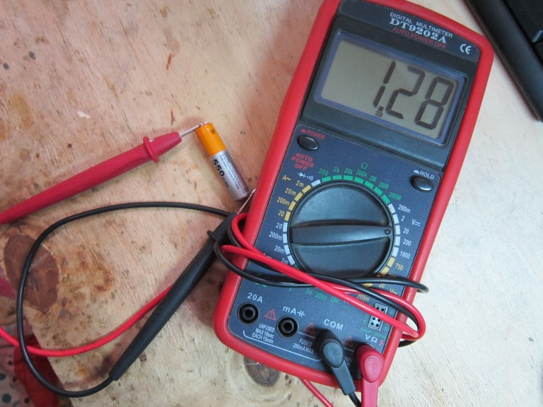
IN in this case battery voltage is 1.28 volts. Value on new battery should always exceed what is written on the label.
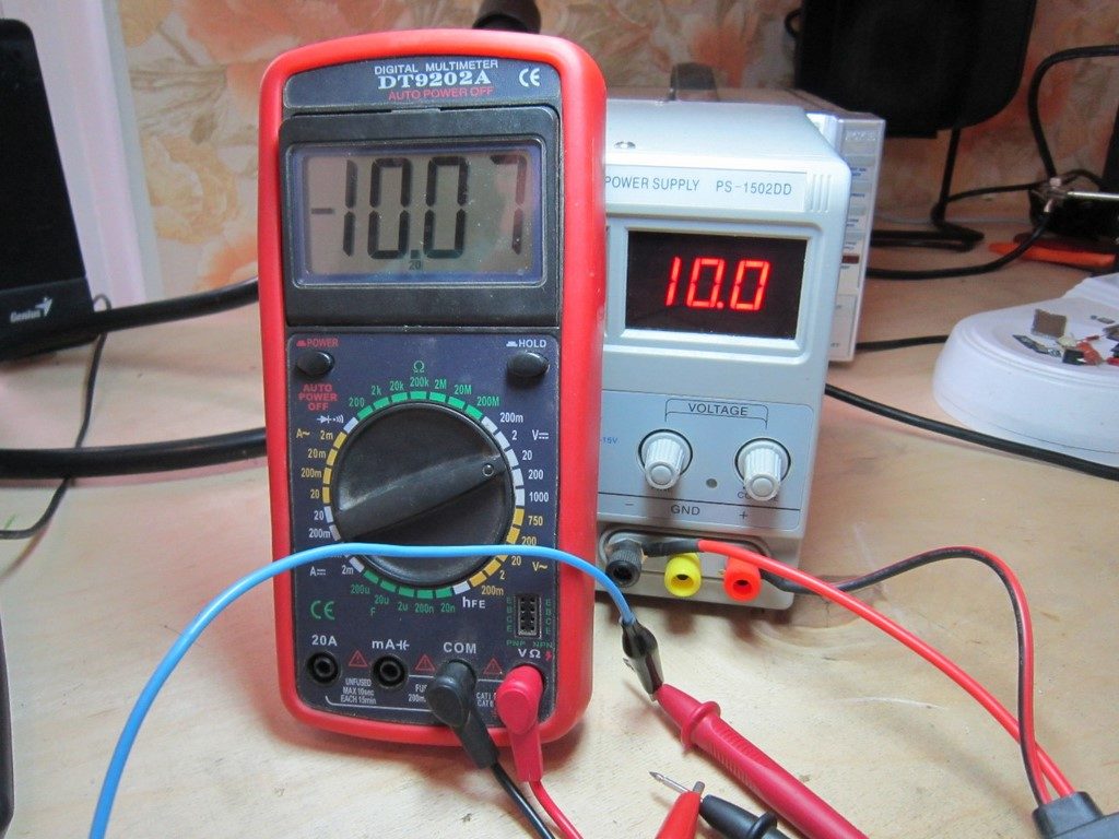
Let's measure the voltage on the power supply. We set it to 10 Volts and measure it.

Red is a plus, black is a minus. Everything matches, the voltage is 10.09 Volts. We'll write off 0.09 Volts as an error.
If we confuse the multimeter probes or the unit probes, then nothing bad will happen. The multimeter will show us the same value, but with a minus sign.
Keep in mind, this does not work on such multimeters
.jpg)
In order to accurately determine the polarity without a multimeter, you can resort to several tips that are described in the article.
How to measure AC voltage with a multimeter
We set the limit for measuring alternating voltage on the cartoon and measure the voltage in the outlet. It doesn't matter how you insert the probes. There is no plus or minus. There is a phase and a zero. Roughly speaking, one wire in a socket does not pose a danger - it is a zero, while the other can greatly ruin your well-being or even your health - this is a phase.
.JPG)
In theory, the outlet should have 220 Volts. But mine shows 215. There’s nothing wrong with that. The voltage in the socket “plays”. You are unlikely to see exactly 220 Volts when measuring the voltage in the sockets of your home :-)
Current along with voltage and resistance is a very important concept in electricity. It is measured in amperes and is determined by the number electrical energy passing through a conductor in a certain unit of time. Its value is determined using measuring instruments; at home this is easiest to do using a multimeter or tester, which is available to many owners modern apartments. Current control is very important for the operation of power-dependent mechanisms, since exceeding the maximum permissible value leads to equipment failure and emergency situations. The topic of this article is how to measure current with a multimeter.
Types of multimeters
On modern market There are two types of testers for electrical appliances:
- Analog.
- Digital.
The main elements of analog instruments are a scale with divisions marked on it, which is used to determine the indicators of electrical quantities, and an arrow-pointer. Such multimeters are in high demand among beginners due to their low cost and ease of use.

But, along with these positive aspects, analog testers They also have a number of disadvantages, the main one of which is the high measurement error. It can be somewhat reduced due to the tuning resistor, which is structurally included in the device. However, if necessary, measure electrical parameters With high accuracy, it is better to use a digital device.
Digital multimeters
The only one external difference The difference between a digital device and an analog one is the screen on which the measured parameters are reflected in the form of numbers. Old models are equipped with an LED display, while new types of devices are equipped with a liquid crystal display.
They are distinguished by high measurement accuracy and ease of operation, since they do not require adjustment of the calibration.
The disadvantage of these devices is the price, which is several times higher than the cost of analog testers.
Design Features
Regardless of the number of sockets in the multimeter, any of these devices has two types of outputs, which are indicated by different colors. The common output (ground) is colored black and is designated either “com” or “–”. The output intended for measurements (potential) is red. Any of the measured parameters of the electrical circuit can have its own socket.

There is no need to be afraid of confusing it with others, since each of these slots is designated by the corresponding unit.
One more external element The device is a handle for setting the measurement limit, which can rotate in a circle. On digital multimeters these limits are greater than analog ones, in addition, they can include additional options, For example, sound signal and others. Since we are talking about how to measure current using a tester, we will talk about a scale with amperes.
Each multimeter has its own maximum current limit, and when choosing an electrical network for testing, the current strength being tested in it should be compared with the limit for which the device is designed. So, if the current flowing inside the electrical circuit is 180 A, it is not recommended to carry out measurements using a multimeter rated at 20 A, since the only result obtained will be the device burning out immediately after testing begins. The maximum limit is always indicated in the multimeter data sheet or on the device body.
The procedure for preparing the device for measurements
The multimeter switch must be moved to sector A (DA for direct current or CA for alternating current), which corresponds to the current measurement, selecting the desired limit. Some modern testers for DC circuits have one position, and for alternating current - another. In order not to make a mistake, you need to be guided by the letters on the front panel.

They are the same in any device, you just need to understand what value each of them represents.
All multimeters are equipped with two cables, at the end of each of which there is a probe and a connector. The second ends of the wires are inserted into the sockets of the device, which correspond to the current measurement, in our case, current strength.
Measurement order
A multimeter for measuring current is connected to an open circuit. This is the main difference from the voltage measurement procedure, in which the tester is connected to the circuit in parallel. The indicator of the amount of current that passes through the device is displayed by an arrow on the scale (if we're talking about about the analog device) or is displayed on the liquid crystal (LED) display.
There are different ways to break the circuit under test to connect the device to it. For example, by disconnecting one of the terminals of the radio element using a soldering iron.
Sometimes you have to cut the wire with wire cutters or pliers.
When determining the current value of a battery or accumulator, such a problem does not exist, since a circuit is simply assembled, one of the elements of which is a multimeter.
What to consider when measuring
An important condition when determining the current strength is the inclusion of a limiting resistance in the circuit - a resistor or an ordinary light bulb. This element will protect the device from damage (combustion) under the influence of electron flow.

If the current strength is not displayed on the indicator, this indicates an incorrectly selected limit that needs to be reduced by one position. If there is no result again, do one more, continuing until some value is displayed on the screen or scale.
The measurement must be taken quickly - the probe should not be in contact with the cable for more than one or two seconds. This is especially true for low power batteries. If, while measuring the current strength of the batteries, you hold the probe on the wire for a long time, the result will be their discharge - partial or complete.
Safety precautions
As you can see, the procedure for measuring current using a multimeter is not difficult. It is only important to follow the instructions and do not forget about strict adherence to safety measures:
- Before taking measurements, turn off the power supply.
- Check the cable insulation - with prolonged use, its integrity is sometimes compromised, and the likelihood of electric shock increases significantly.
- Work exclusively with rubber gloves.

- Do not take measurements in high air humidity. The fact is that moisture has high electrical conductivity and the risk of damage also increases.
- A person who has suffered an electric shock needs medical attention. If possible, it is better to carry out any work with electricity, including measurements, together. In an emergency situation, the presence of a partner can be a real salvation.
Having completed the measurements, the cut cables must be reconnected, having first de-energized the circuit again.
In detail and clearly about measurements carried out using a multimeter in the video:
Conclusion
In this article, we figured out how to check the current strength using a multimeter. After reading the material presented, any adult will be able to cope with this task, since a multimeter is a very simple device, but at the same time very necessary for solving not only professional, but also everyday problems related to electricity.
Measurement of direct current and voltage is most often carried out by panel devices of magnetoelectric, and when measuring high voltages - electrostatic and ion systems. Sometimes devices of electromagnetic, electrodynamic and ferrodynamic systems are used; they are significantly inferior to devices of the magnetoelectric system in terms of accuracy, sensitivity, power consumption, have an uneven scale, and are sensitive to the effects of external magnetic fields. For precise measurements are increasingly used digital voltmeters, ammeters and combined instruments, having high speed and low measurement error (0.01-0.1%).
The simplest way to measure voltage is to directly connect devices to the circuit, which is possible if the following conditions are met:
1) the maximum measurement limit of an ammeter (voltmeter) is not less than the maximum current (voltage) in the circuit;
2) the rated voltage of the ammeter is not less than the rated voltage of the network;
3) the resistance of the ammeter Ra is much less, and the resistance of the voltmeter is much greater than the resistance of the measured circuit Rн; significant resistance of the ammeter reduces the current in the circuit when it is turned on by an amount
![]()
4) observing the polarity of switching on devices.

To expand the measurement limits of devices, converters are used in the form of additional resistances, voltage dividers, instrument transformers and instrument amplifiers. A shunt is a resistance connected parallel to the measuring device in the circuit of the measured current. Shunts for currents up to 50-100 A are usually installed inside the device. For high currents, external shunts are used that have current terminals for connecting the measured current into the circuit and potential terminals for connecting a measuring device. In order to unify measuring instruments, shunts are manufactured according to GOST 8042-78 shunts 0.05-0.5.

By connecting a millivoltmeter with a measurement limit corresponding to the rated voltage drop across the shunt to the shunt, we obtain that the full scale of the device corresponds to the rated current of the shunt. Measured current
where Iн, Un - rated shunt current and voltage drop across the shunt; U - millivoltmeter reading.
To expand the measurement limits of voltmeters in series with measuring instrument include additional resistance Rd.

Measured voltage
![]()
where Р = Rд /Rв+1 - coefficient of expansion of the measuring limit of the device; Uv - voltmeter reading;
Rv - input resistance of the voltmeter.
Additional resistances can be either internal (placed in the device body) or external for measuring voltages above 500 V.
 The rated currents of additional resistances are standardized by GOST 8623-78 at the rated voltage drop across them. The main error of additional resistances is ± (0.1-0.5)%. To expand the measurement limits of devices with high input impedance, voltage dividers with a fixed division coefficient, usually a multiple of 10, are used. In installations high voltage DC power transmission and in high-current circuits, in addition to the indicated converters, DC measuring transformers can be used.


