How to check the output voltage. How to check the power supply, power adapter, charger
The power supply is one of the most unreliable components of the system unit. And often the problem is not the quality of the power supply itself, but the quality of our electrical network, which is far from the ideal 220V.
It is not at all necessary that if the power supply is faulty, the computer does not turn on at all. Very often the computer starts to reboot or shut down spontaneously. Such failures are associated with a lack of power to components or overheating.
So, here are the steps to diagnose PD! (we do not take cases with a clear smell of burning or smoke :-))
- Checking the cooling;
- Checking the voltage;
Checking the cooling.
Usually, to diagnose overheating, it is enough to put your hand directly to the top cover of the system unit, right where the power supply is located. If the lid “bulges” with heat, overheating is obvious. The cause of overheating is a faulty cooling fan in the power supply.
To check it, just turn the blades with a thin screwdriver. The working fan will make several revolutions even with a slight push with a screwdriver. A faulty fan turns with noticeable effort, or does not turn at all.
To eliminate overheating, it is enough to replace the fan and clean the power supply from dust.
Sometimes it is possible to develop an old fan by dropping a drop of machine oil into its core, but this should be done only in extreme cases, if it is not possible to buy a new fan, which costs between 100-300 rubles.
Check the voltage of the power supply.
P.S. For the most advanced, it appeared on my website new article in which I tell you how you can test the power supply with a special tester.
- article - checking the power supply with a special tester
- tester - http://aliexpress.com/power_supply_tester
If everything is in order with the cooling, we undertake to diagnose the voltage that the power supply produces. For this we need a multimeter or voltmeter.
Considering that voltmeters are gradually becoming a thing of the past, I will use a multimeter like this.
For testing no need to take it out power supply from the case. It is enough to disconnect all the power supply wires from the components, but for ease of testing I still took it out.
Don’t forget to switch the multimeter to DC measurement mode with a voltage of up to 20 volts.

Security measures
Always be very careful when working with electricity. Check the integrity of the braid of all cables before use. Do not touch the parts with bare or, especially, wet hands. If you are not confident in your abilities, entrust this work to a professional.
1. At first connect the power supply to the electrical network.

2. Once connected, we need to make the power supply work as if we turned on the computer. To do this, you need to short-circuit the thickest loop of wires. green and any of black wires To do this, it is convenient to use a regular paper clip.
Before you start the unit, you need to connect some kind of load to it, for example, an optical drive.
Unbend the paper clip and close the contacts, as shown in the photo.


The power supply cooler should spin up, which means that we did everything correctly; if not, then most likely the power supply is faulty and needs to be replaced.
3. We measure the voltage using a multimeter.
To do this, we plug the black probe into the molex connector opposite any black wire (2 middle connectors).

Then, using the red probe, we begin to touch the contacts on the wide cable one by one and look at the multimeter readings.

Here power supply pinout diagram.
Everything is simple here, you need to measure the voltage at different contacts. Using the diagram it will be easy to determine what voltage a working power supply should have. For example, all red wires should have 5V, all yellow wires should have 12V, and orange wires should have 3.3V.


As you can see from the photos, my power supply turned out to be quite working :)
If the voltage was less than necessary (for example, 4V instead of 5V), this is a sure sign that the power supply is faulty and needs to be repaired.
If your PSU is faulty and you decide to buy a new one, here are some tips to help you spend your money wisely.
- Don't buy the cheapest models. As a rule, their quality corresponds to their price. When assembling such blocks, they save on everything, including the quality of radio components and the quality of their installation.
- Don't chase Wats. If you are choosing a power supply for a computer with an integrated video card, it is quite enough 350W-400W. For a computer with a powerful video card for gaming - 450W-550W.
- If you are offered to buy a 500W power supply, despite the fact that similarly priced models from other manufacturers are only rated at 350W, think about the quality of such a unit.
- A good power supply will be noticeably heavier than low-quality models.
Proper nutrition is the key to the health of your computer! 🙂
P.S. Time flies, my site is already 5 months old. It’s hard to imagine how much has been done during this time. It seems that just recently I was choosing a topic for myself, thinking about its content, worrying whether the site would be interesting to readers.
Now I understand that I’m just interested in doing this. Of course, your own website takes some time, but believe me, it's worth it!
Sometimes it becomes necessary to do a computer stability test. For example, stability is usually checked after building or purchasing a new computer. It is also advisable to carry out a stability test after replacing components or after servicing the computer. This allows you to identify possible problems at an early stage and take the necessary actions.
Computer stability testing is usually carried out in stages. First, they check the stability of the processor, then the stability of the video card, and so on. Creating an accentuated load on individual components allows you to quickly determine the source of problems if the computer does not work stably.
To create the maximum load on computer components, you need specialized programs designed specifically for testing. After all, even the most demanding professional programs or computer games do not create the necessary loads. For example, you can use the LinX program to test a Furmark video card, and to test an S&M power supply. There are also universal programs that include different tests. One of the most popular programs of this kind is the OCCT program. This program allows you to conduct a stability test for all major computer components (processor, video card, power supply). At the same time, OCCT has its own built-in system monitoring, which allows you to monitor load levels, temperatures, voltages and much more.
In this article we will use OCCT, since it is more convenient and saves time on installing programs. You can download OCCT on the official website. Also, when testing, you may need a program, more about this at the end of the article.
It should be noted that a computer stability test can lead to computer failure, for example due to overheating. Although this is very unlikely, it is a possibility. Therefore, everything you do is done at your own responsibility.
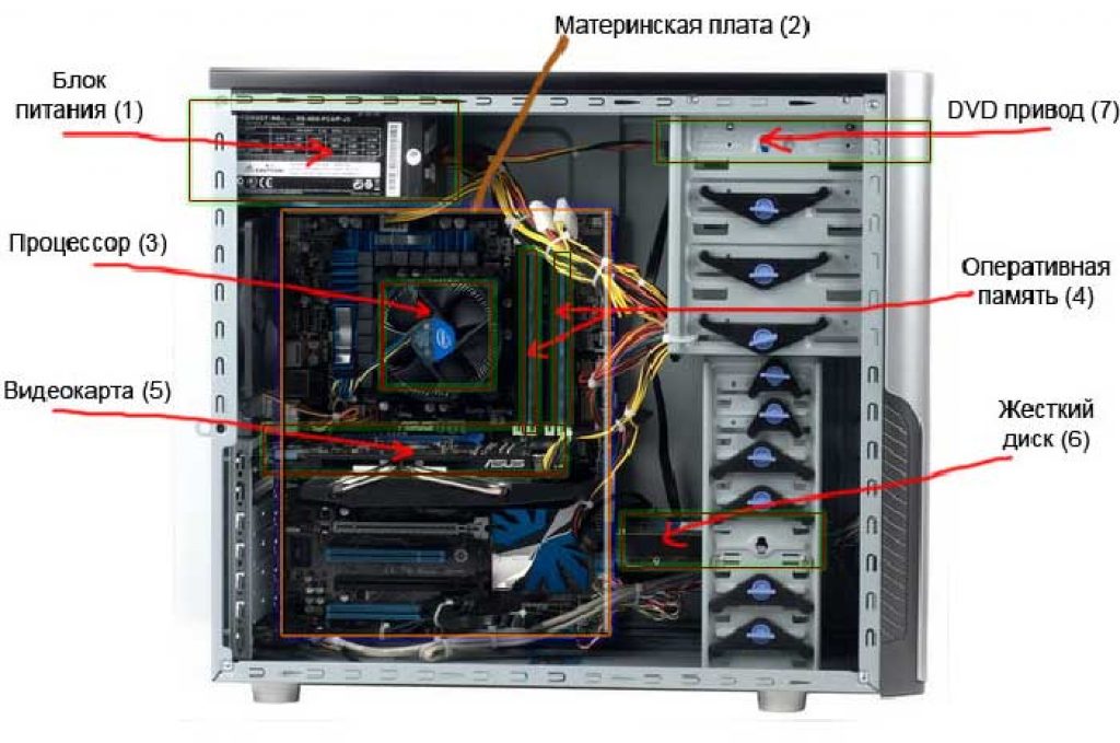
If your computer often freezes or constantly requires a reboot, or does not turn on at all, then a possible cause of such problems is a faulty power supply.
The power supply supplies power to all components of the computer case. It transforms the incoming alternating voltage into direct voltage.
Symptoms of malfunction
There are a number of signs characteristic of a malfunctioning battery. The power supply does not operate in the desired mode under the following conditions:
- Pressing the power button does not start the system unit. There is no light or sound response to switching on. Coolers do not rotate. In such a situation, there may be a malfunction of the power supply or there may be breaks in the wires, weak AC supply from the network;
- The computer does not turn on the first time. The problem is either in the power supply, or in a loose connection of the connectors, or in a malfunction of the power button;
- The computer turns off for no apparent reason when the operating system is loading. The reason for this may be intermittent transmission of voltage from the power supply to other computer components. This malfunction may also indicate that the power supply is overheating and, as a result, it is forced to shut down.
- Presence of a blue screen.
- Presence of a burning smell.
Unit inspection

Attention!
Checking the correct operation of the computer power supply involves carrying out certain manipulations under voltage. Be extremely careful to avoid accidents. Before starting the test, inspect the integrity of each cable. Do not touch parts with wet, unprotected hands.
1 Visual check of the power supply.
This is the first and easiest way to check.
- Unscrew 4 (or 6) screws, disconnect the unit from the computer case;
- Unscrew the screws that are in the unit body and disassemble it;
- Carefully inspect the power supply chip. Pay close attention to the capacitors.
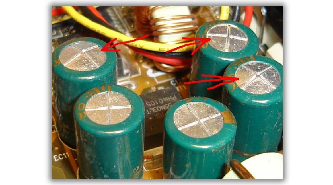
If any of them are swollen, then the power supply protection is faulty. Urgent replacement of parts is required.
If no problems are found in the capacitors, we recommend removing dust from the power supply, lubricating the fan and reassembling the device, and then try connecting the computer.
Power check
This test is carried out by turning on the power supply without connecting it to the motherboard.
- Turn off your computer. Then turn off the switch on the back of the computer's power supply.
- Remove the computer cover. Disconnect the power supply from other parts of the computer. Disconnect each cable. Be sure to remember or take a photo of the order in which all the elements are connected so that you can reconnect all the cables later.
- Take the motherboard power cable that comes from the power supply. Find the green wire.
- It must be connected to any of the black wires. Do this using a paperclip or a small piece of wire.

- Connect any device to the power supply. For example, an old unnecessary hard drive. This is necessary to give the power supply a certain load, the absence of which can lead to damage to the unit.
- Connect the power supply to the network and press the power button on the unit body.
If the fan starts to rotate, it means the power supply is working.
Even if this test method showed that the power supply is working, this does not mean that it is completely working.
Checking with a multimeter

Now you need to check whether the power supply transmits full DC voltage. For this:
- Unplug the power supply and use a paperclip or piece of wire to short-circuit the motherboard cable. This will bring the unit into working condition.
- Apply any external load to the power supply. Connect a floppy drive, hard drive or cooler to it;
- Take a multimeter - this is a universal tester that measures current strength. Set the tester to DC voltage test mode.
- Check the voltage between the orange and black wires, between the red and black wires, and between the yellow and black wires.
- We plug the black probe of the multimeter into the connector opposite the black wire, and connect the red probe of the tester in turn to the connector contacts to which the wires of the colors we need fit.
A functioning power supply will produce the following voltage values:
- 3 Volts for orange wire;
- 5 Volts for red wire;
- 12 Volts for yellow wire.
If the test you carried out shows that the power supply is faulty, you can disassemble it and repair it. After completing the work, collect all the contacts and install them correctly.
If the test showed that your power supply is working, but difficulties with the computer continue, then most likely the reason is something else.
Good day, dear friends, acquaintances, readers, admirers and other individuals. Today we will test the computer through OCCT.
It is often necessary to find out the cause of problems, and simply any problems, from reboots/freezes to computer shutdowns.
In “field” (i.e., in normal working) conditions, this is not always possible, because some problems have a rather peculiar, so to speak, floating character and are not so easy to diagnose. And usually it’s not enough to just find out what is to blame and not the software part, but you also need to understand what exactly is plotting, or rather what specific piece of hardware is faulty. In such situations, specialized software comes to our aid to check stability.
Do you want to know and be able to do more yourself?
We offer you training in the following areas: computers, programs, administration, servers, networks, website building, SEO and more. Find out the details now!
After launch, we will see a red one in front of us USSR-shaped program window (see screenshot above) in which, in theory, the Russian language should be immediately set. Before this, a window with a donation button may appear, for now you can close it (well, or immediately support the developer, it’s up to you).

If this is not the case, then click on the gear icon on the right, and then set the desired parameter. Or use it as is.
How to test a computer in general
The program has a set of tabs:
- CPU:OCCT And CPU:LINKPACK, - testing processor stability under stressful conditions (load, power supply, temperature, etc.);
- GPU:3D, - testing the stability of the video card;
- POWER SUPPLY, - testing the stability of batteries (motherboard, power supply, circuits, etc., in general, load tests).
Let's try each of them, because each has its own parameters.
ATTENTION! Use with caution OCCT on laptops due to the high load and heating generated. On laptops with a weak/damaged cooling system (and other elements), this can lead to unpredictable consequences. Probably wise to use on them AIDA64.
Before the test, go to the above-mentioned settings (where you set the language) and set the processor temperature limiter (most often 85 too high value) and other (if necessary) components.
This is done as follows. We exhibit:
- Test type: auto;
- Test duration: 1 hour 0 minutes;
- Test mode: Large dataset.
Comments on the items raised:
- Runs for the specified time, i.e. an hour or more (or until an error is detected), allows you not to waste extra time on diagnostics;
- Test time, is the test time;
- Data set, - determines the load level and the heat generated, as well as the number of elements being tested. If the data set is small, then only the processor is tested; if it is medium, then the processor + memory; if it is large, then the processor + memory + chipset. In a large set, the heating is stronger, but you can find more errors; in a small set, there is less heating, but you can miss something important;
Other parameters:
- Inaction at the beginning and at the end - leave it as is, allows you to reduce the load before/after launch and read the necessary data;
- Test version, - select the one that matches the installed version of the operating system;
- Number of threads, - as a rule, a tick " is enough Auto", but if it is determined incorrectly (less than the number of physical and logical processor cores), then you can set it manually by unchecking it.
ON
The second tab, namely CPU: LINPACK, is another test, but exclusively of the processor, and not of many elements at once (see the description of the first tab above).
Testing Warning
Worth with caution relate to this test, because it loads and heats up the processor extremely (including the core power supply, if supported by the motherboard) and is extremely extreme test. Recommended to use only in the presence of a powerful cooling system and an urgent need to diagnose it and the processor. In other cases, it is better to use the first test.
For those who have decided (usually required if the first test did not reveal problems, but “visually” they are preserved):
- Test type: auto;
- Test duration: 1 hour 0 minutes;
- Test mode: 90% memory (I recommend closing all possible programs, etc., or reducing this value to 70-80%);
- 64 bit
- AVX-compatible Linkpack
Then all you have to do is press the button ON and wait an hour (or less, if an error is found, the computer freezes, turns off, or shows some other signs of overheating and failure) while the system is scanned. The analysis of the results is described at the end of the article.
Supported Crossfire And SLI, checking and identifying many errors during strong heating during loads, and also, using a special system, artifacts (image distortions) are determined. You can do testing with different numbers of shaders, FPS and everything else.
Here, in fact, we present the following:
- Test type: auto
- Test duration: 1 hour 0 minutes
- DirectX version
- Permission
- Type: fullscreen (checkmark);
- Checking for errors: for the first test there is usually no need to check it, for the second (if the problem visually persists, but no errors are found) it makes sense to check the box;
- Shader complexity: in general, this parameter is responsible for the number of operations performed by the video card in one pass (most often, the maximum available value is selected, or, if you need to specifically test for an application, then select the value that the application uses);
- Limiter: 0 (zero), or 60 (if you use vertical synchronization and need to test the work for it).
Then all you have to do is press the button ON and wait an hour (or less, if an error is found, the computer freezes, turns off, or shows some other signs of overheating and failure) while the system is scanned. The analysis of the results is described at the end of the article.
The test itself looks usually like in the screenshot above. It does not start immediately (see periods of inactivity), it can change the type of picture (image). Significant visual distortions (it is difficult to confuse them with something else) are artifacts and indicate problems with the video card, its memory and something else.
ATTENTION! Quite complex to analyze, it is recommended to use it only if the first tests did not reveal anything in any way, but the problems persist. Dangerous and definitely not suitable for cheap ( noname) and low-quality power supplies. Use at your own risk.
Similar to the previous test, the following is set here:
- Test type: auto
- Test duration: 1 hour 0 minutes
- DirectX version: if available, then 11, if not, then 9, if you need to specifically test for some application, then select the value that the application uses;
- Permission: current, or, if you need to specifically test for some application, then select the value that the application uses;
- Type: full screen mode (checkmark);
- 64 bit: if the system and processor support;
- AVX-compatible Linkpack, - it makes sense to avoid if you don’t know what we’re talking about;
- Use all logical cores, - must be checked if the checkbox is available (may not be available if they are not present or there is no access to them).
Then all you have to do is press the button ON and wait an hour (or less, if an error is found, the computer freezes, turns off, or shows some other signs of overheating and failure) while the system is scanned. The analysis of the results is described below.
Analysis of test results OCCT
As a result of the tests, you can get the following result:
- Charts, - most often, in the absence of a severe physical failure (shutdown, reboot, freeze, etc.), are the result of any test, contain temperatures, voltages and other data for analysis;
- Error(in the program) - usually this is a kernel error or something else that stops the test (but the computer is working), most often its number or at least a brief description is indicated (kernel failure of such and such);
- Blue screen of death, - that it makes sense to read;
- Physical failure(or protection triggered), - shutdown, reboot, freeze and similar horrors of life.
How to take off with this;
- For analysis temperature charts read (pay special attention to the maximum permissible values); if in doubt, see the documentation for the overheating component (paper, or on the manufacturer’s website) to analyze the maximum permissible temperatures;
- For analysis nutrition-related charts, it is worth understanding that minor discrepancies are acceptable (tenths, hundredths, or less, orders of magnitude), excluding certain values (for example, processor power can change quite significantly due to energy saving technologies, frequency regulation, overclocking, etc.). If it’s difficult to figure it out, then contact us on the forum) for a more powerful one, or they (failures) are a consequence of a complete failure of the component. The latter are the most difficult to diagnose; most often, failures of the power supply (not completely turning off the computer or not turning on right away) and/or video card (image artifacts) are immediately clear.
If complex problems arise that need to be sorted out by looking at graphs and so on, then contact us, for example, on the forum.
Afterword
I repeat that this is one of the most powerful stability tests that, in principle, can be found. It is quite often used by overclockers (those who overclock computer components) to check stability, which says a lot.
As always, if you have any (reasonable) thoughts, questions, thanks or additions, then, as usual, write them in the comments to this article (or on the forum mentioned above).
Thank you for being with us.
Stability to you!
Today we will talk about how to check your computer? We will carry out the test using two different measuring instruments: a multimeter (multitester) and one Chinese “device” :) We will use them to carry out the necessary measurements and try to identify the malfunction of the computer’s power supply. Let's hope that with the help of these devices, checking the power supply will be not only successful, but also educational!
Let's start, as expected, with a little background. There was a case in our IT department: the user’s workstation turned on after the third or fourth time. Then it stopped loading completely. In general - a “classic of the genre”, all the fans are spinning, but...
We blame the power supply on a fault. How can you and I check the computer power supply? Let's remove it from the case, run it autonomously and measure the voltage at its output.
As already mentioned, we will check the power supply with two different measuring instruments: one nameless Chinese device and the most ordinary multimeter for 10-15 dollars. So we will immediately kill two birds with one stone: we will learn how to work with these meters and compare their readings with each other.
I suggest starting with a simple rule: The voltage of the power supply must be checked by first loading the power supply itself with something. The fact is that without the “load” we will receive inaccurate (slightly inflated) measurement results (do we need it?). According to recommendations standard for power supplies, they should not start at all without connecting a load to them.
Of course, (in the case of taking measurements with a multimeter) you don’t have to disconnect the power supply from it (thus preserving the workload for it), but then I simply won’t be able to properly photograph the measurement process for you :)
So, I propose to load our power supply with an ordinary 8-centimeter external fan at 12V (two possible), which we will connect to the “Molex” connector of the test subject while testing the power supply. Like this:
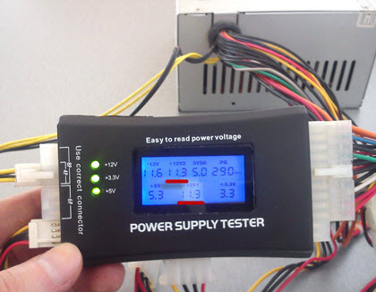
And this is what our Chinese tester (a thing in itself) looks like for checking the power supply that I talked about earlier:

As you can see, the device has no name. The inscription “Power Supply Tester” (power supply tester) and that’s it. But we don’t need a name; we need it to take adequate measurements.
I have labeled the main connectors from which this device can take readings, so everything is simple here. The only thing is, before you start checking the computer’s power supply, make sure that you have correctly connected the additional 4-pin 12V plug. It is used when connected to the corresponding connector near the central processor.
Let's look at this point in more detail. Here is a close-up of the part of the device that interests us:

Attention! Do you see the warning message "Use correct connector"? (use suitable connector). If the connection is incorrect, not only will we not be able to check the power supply correctly, we will ruin the meter itself! What should you pay attention to here? For the clues: “8P (pin)”, “4P (pin)” and “6P (pin)”? A 4-pin (12-volt) processor power plug is connected to the 4-pin connector, a six-pin additional power connector (for example, a video card) is connected to “6P”, and an 8-pin connector is connected to “8P”, respectively. . Only this way and no other way!
Let's see how to check the power supply with this device under "combat" conditions? :) Open it up, carefully connect the connectors we need to the tester and look at the screen with the measurement results.

In the photo above we can see the measurement indicators on the digital display. I propose to sort them all out in order. First of all, you should pay attention to the three green LEDs on the left. They indicate the presence of voltage along the main lines: 12, 3.3 and 5V.
The numerical measurement result is displayed in the center of the screen. Moreover, both positive values and voltage values with a minus sign are displayed.
Let's look at the photo above again and, from left to right, go through all the tester's indications when checking the computer's power supply.
- - 12V (available - 11.7V) - normal
- + 12V2 (12.2V available) - current on a separate 4-pin connector near the processor)
- 5VSB (5.1V) - here V=Volt, S.B. - "standby" (standby voltage - "standby"), with a nominal value of 5V, which are set at a given level no later than 2 seconds after the unit is connected to the network.
- PG 300ms - "Power Good" signal. Measured in milliseconds (ms). Let's talk about it a little lower :)
- 5V (there is 5.1V) - lines that serve to supply energy to hard drives, optical drives, floppy drives and other devices.
- + 12V1 (12.2V) - which are supplied to the main (20 or 24-pin connector) and disk device connectors.
- + 3.3 V (available - 3.5V) - used to supply power to expansion cards (also present on the SATA connector).
We checked the power supply, which was fully operational (to get the hang of it), so to speak :) Now the question is how to check the power supply of a computer that makes us suspicious? This article began with him, remember? We remove the power supply, attach a load (fan) to it and connect it to our tester.
Pay attention to the highlighted areas. We see that the voltage of the computer's power supply along lines 12V1 and 12V2 is 11.3 V (at a nominal value of 12V).
Is it good or bad? You ask:) I answer: according to the standard, there are clearly defined limits of acceptable values that are considered “normal”. Everything that doesn’t fit into them sometimes works great, but often it’s buggy or doesn’t turn on at all :)
For clarity, here is a table of the permissible voltage spread:

The first column shows us all the main lines that are in the power supply. Column " Tolerance"this is the maximum permissible deviation from the norm (in percentage). According to it, in the field" min" indicates the minimum permissible value along this line. Column " nom" gives the nominal (recommended indicator, according to the standard). And - " Max" - maximum permissible.
As you can see, (in one of the previous photographs) our measurement result along lines 12V1 and 12V1 is 11.30V and it does not fit into the standard five percent spread (from 11.40 to 12.60V). This malfunction of the power supply, apparently, leads to the fact that it starts at all or the third time.
So, we have discovered a suspicious malfunction. But how can you carry out an additional check and make sure that the problem is precisely the low voltage +12V? Using our (most common) multimeter under the brand " XL830L».
How to test a power supply using a multimeter?
We will start the block as described in, closing two contacts (pins) with a paper clip or a piece of wire of a suitable diameter.

Now - we connect an external fan to the power supply (remember about the “load”) and - a 220V cable. If we did everything correctly, the external fan and the “Carlson” on the unit itself will begin to rotate. The picture at this stage looks like this:

The photo shows the devices with which we will check the power supply. We already looked at the work of the tester from the Middle Kingdom at the beginning of the article, now we will make the same measurements, but with the help.
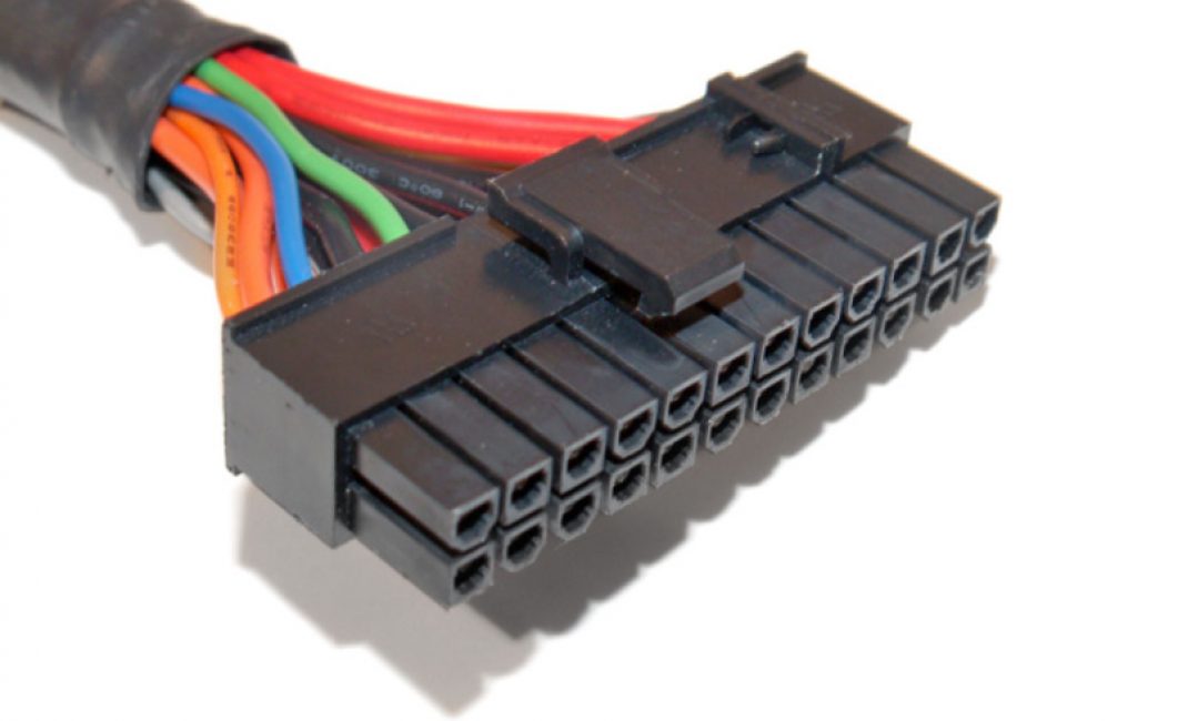
Here you need to digress a little and take a closer look at the computer’s power supply connector itself. More precisely, the voltages that are present in it. As we can see (in one of the previous photos) it consists of 20 (or 24 four) wires of different colors.
These colors are used for a reason, but mean very specific things:
- Black the color is “ground” (COM, aka common wire or ground)
- Yellow color + 12V
- Red: +5V
- Orange color: +3.3V
I suggest checking and considering each pin separately:

This is much clearer, isn’t it? You remember about colors, right? (black, yellow, red and orange). This is the main thing we need to remember and understand before checking the power supply ourselves. But there are a few more pins that we need to pay attention to.
First of all, these are the wires:
- Green PS-ON - when it is shorted to ground, the power supply starts up. In the diagram this is shown as “PSU On”. It is these two contacts that we close with a paper clip. The voltage on it should be 5V.
- Next - gray and the “Power Good” or “Power OK” signal transmitted through it. Also 5V (see note)
- Immediately behind it is a purple one marked 5VSB (5V Standby). This is five volts of standby voltage ( duty room). It is supplied to the computer even when it is turned off (the 220V cable must, of course, be connected). This is necessary, for example, in order to be able to send a command to a remote computer over the network to launch “Wake On Lan”.
- White (minus five volts) - now practically not used. Previously, it served to provide current to expansion cards installed in the ISA slot.
- Blue (minus twelve Volts) - currently consumed by the “RS232” (COM port), “FireWire” and some PCI expansion cards.
Before checking the power supply with a multimeter, let’s look at two more of its connectors: an additional 4-pin for the needs of the processor and a “Molex” connector for connecting optical drives.

Here we see the colors already familiar to us (yellow, red and black) and their corresponding values: + 12 and + 5V.
For greater clarity, download all power supply voltages in a separate archive.
Now let’s make sure that the theoretical knowledge we have received is fully confirmed in practice. How? I suggest starting with a careful study of the factory “sticker” (sticker) on one of the real ATX power supplies.

Notice what is underlined in red. "DC OUTPUT" (Direct Current Output - DC output value).
- +5V=30A (RED) - plus five IN, provides a current of 30 Amperes (red wire) We remember from the text above that we receive exactly +5V along the red wire?
- +12V=10A (YELLOW) - plus twelve IN we have a current of ten amperes (its wire is yellow)
- +3.3V=20A (ORANGE) - three point three line IN can withstand twenty amps of current (orange)
- -5V (WHITE) - minus five IN- similar to described above (white)
- -12V (BLUE) - minus twelve IN(blue)
- +5Vsb (PURPLE) - plus five IN standby. We have already talked about it above (it is purple).
- PG (GRAY) - Power Good signal (gray).
On a note: if, for example, the standby voltage according to measurements is not five volts, but, say, four, then it is very likely that we are dealing with a problematic voltage stabilizer (zener diode), which should be replaced with a similar one.
And the last entry from the list above tells us that the maximum output power of the product in watts is 400W, and only the 3 and 5V channels can provide a total of 195 watts.
Note: « "Power Good"- “nutrition is normal.” A voltage of 3 to 6 Volts (nominal 5V) is generated after the necessary internal checks through 100 - 500 ms(milliseconds, it turns out - from 0.1 to 0.5 seconds) after switching on. After this, the clock generator chip generates an initial setting signal. If it is missing, then another signal appears on the motherboard - a CPU hardware reset, preventing the computer from working with abnormal or unstable power.
If the output voltage does not correspond to the nominal voltage (for example, when it decreases in the mains), the “Power Good” signal disappears and the processor automatically restarts. When all required current values “P.G.” are restored is formed anew and the computer starts working as if it had just been turned on. Thanks to the quick turn off of the “Power Good” signal, the PC “does not notice” problems in the power system, since it stops operation before errors and other problems associated with its instability may appear.
In a properly designed unit, the issuance of the “Power Good” command is delayed until the power supply in all circuits is stabilized. In cheap power supplies, this delay is insufficient and the processor starts working too early, which, in itself, can even lead to corruption of the contents of the CMOS memory.
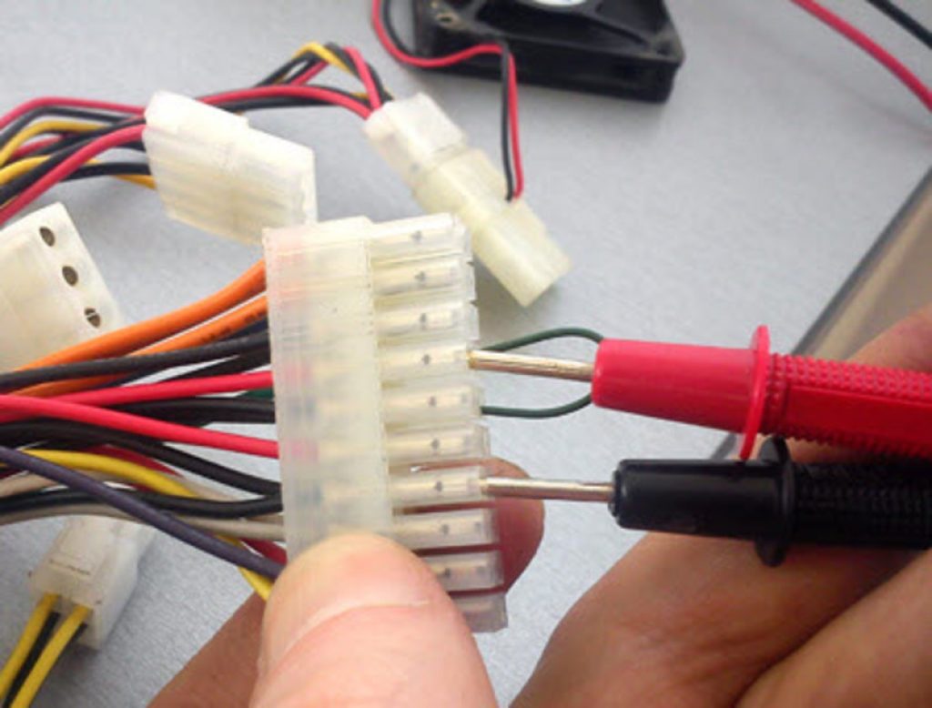
Now, armed with the necessary theoretical knowledge, we understand how to properly check a computer’s power supply using a multitester. We set the measurement limit on the DC scale to 20 Volts and begin checking the power supply.

We apply the black “probe” of the tester to the black “ground” wire, and start “poking” with the red one into all the remaining ones :)
Notes e: don’t worry, even if you start “feeling” for something wrong, you won’t burn anything - you’ll just get incorrect measurement results.
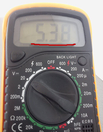
So, what do we see on the multimeter screen when checking the power supply?

On the +12V line the voltage is 11.37V. Remember, the Chinese tester showed us 11.3 (in principle, a similar value). But it still does not reach the minimum permissible of 11.40V.
Also pay attention to two useful buttons on the tester: “Hold” - holding measurement readings on the display and “Back Light” - backlighting the screen (when working in poorly lit rooms).

We see the same (not inspiring) 11.37V.
Now (for completeness) we need to check the power supply for other ratings. Let's test, for example, five Volts on the same Molex.

The black “probe” is to “ground”, and the red one is to the red five-volt pin. Here is the result on the multimeter:
As we can see, the indicators are normal. Similarly, we measure all other wires and compare each result with the nominal value from.
Thus, checking the power supply showed that the device has a greatly underestimated (relative to the nominal) voltage of +12V. Let's, for clarity, once again measure the same line (yellow color on the additional 4-pin connector) on a fully operational device.

We see - 11.92V (remember that the minimum permissible value here is 11.40V). This means we are well within the tolerance.
But checking the computer's power supply is only half the battle. After this, it also needs to be repaired, and we discussed this point in one of the previous articles, which was called.
I hope that now you yourself, if necessary, will be able to check the computer’s power supply, you will know exactly what voltages should be present at its terminals and act in accordance with this.


