How to connect SATA to IDE. We work with hard drives correctly - simple and detailed instructions. Wiring diagram for SATA - power connector and hard drive power connector - SATA
A hard disk is a solid-state drive, which is so called in contrast to a floppy disk, which has not been used by users for a long time. The operation of connecting a hard drive is not so complicated and in many cases the user can do everything independently, without contacting computer specialists.
In what cases do you have to connect hard drives?
- When upgrading, you replace the old drive with a more powerful and larger one.
- To expand disk memory. For example, to place computer games and some applications on a separate hard drive.
- During repair - replacing a failed drive with a functional one.
- To read large amounts of previously recorded information.
Basic provisions
If a system unit with an IDE interface has more than one hard drive, then one of them on the bus is designated as the main one, and the second as the auxiliary one. The first one is called Master, and the other one is called Slave. Such a division is required so that when loading the operating system after turning on, the computer knows exactly which disk is the boot one.
In all cases, you can set the boot sequence from drives using the BIOS settings. And in IDE this is done by installing jumpers on the disk enclosures according to the diagram shown on the enclosure.
By type of interface, hard drives differ between IDE – the old model and SATA – in all new computers. If you have an older model of system unit and you are going to connect a new hard drive with a SATA interface, you will need to purchase a special adapter.
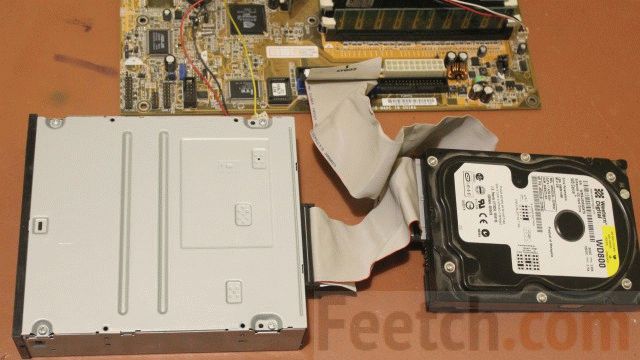
Junk
It happens that you pick up this old thing and can’t figure out what to connect and where. The old IDE interface (1986) is attached to a parallel cable. Usually there are either 2 or 4 connectors on the motherboard. Always an even number, because the Master/Slave rule works. Settings can be specified using jumpers (example):
- Master – the presence of a jumper between the leftmost contacts (7 and 8) of the control connector.
- Slave – absence of any jumpers.
The specified configuration may vary depending on the manufacturer, as well as the set of permissible functions specified by the connector. The IDE interface made it possible to conveniently connect a hard drive and a CD drive to the computer at the same time. This was enough for most users. The disadvantage of the parallel interface was the low transfer speed. IDE is otherwise referred to among professionals as parallel ATA or ATA-1. The transfer speed of such devices does not exceed 133 Mbit/s (for ATA-7). With the introduction of the serial SATA interface in 2003, the aging information transfer protocol began to be called parallel PATA.
The name ATA-1 was assigned to the IDE interface in 1994 when it was recognized by the ANSI organization. Formally, it was an extension of the 16-bit ISA bus (predecessor of PCI). It is curious that in the modern world there is a tendency to use video card interfaces to create ports for connecting hard drives. This was followed by accelerated ATA-2 and packet ATAPI. The IDE interface has not been officially supported since December 2013. Connecting such a hard drive to a new motherboard is only possible with an expansion card.

Using such devices, you can perform the exact opposite function: install previous generation hard drives on new motherboards. So, for example, on the old A7N8X-X there are only two IDE ports, but there are 5 PCI 2.2 slots for expansion cards. The universal adapter is just right for this case. And you can install a modern hard drive up to SATA3, but its operating speed will, of course, be several times lower than the maximum.

Hard drives for standard IDE interfaces are probably already mostly out of order. And there are not so many of them left in the world. It remains to add to this that the configuration of ATA devices can be changed using jumpers, and the explanatory drawing is located directly on the device body. Unscrupulous suppliers sometimes keep jumpers for themselves, and not every configuration in this case can be carried out by the user. There are usually not enough jumpers.
Today there is a new trend: traditional PCI cards, which were supplanted for some time by PCI Express cards, are reappearing on motherboards. This means that “old stuff” can now be connected to a modern system unit using an adapter.

SATA drives
Experts generally distinguish three generations of SATA. The gradation is based on the speed of information transfer:
- SATA – 1.5 Gbit/s.
- SATA2 – 3 Gbit/s.
- SATA3 – 6 Gbit/s.
A standard SATA drive has two connectors, one of which is used for power supply, and the second serves as a data transfer cable. It is not recommended to swap hard drives by connecting them to different SATA ports. The plugs have keys that prevent the connector from being connected incorrectly.

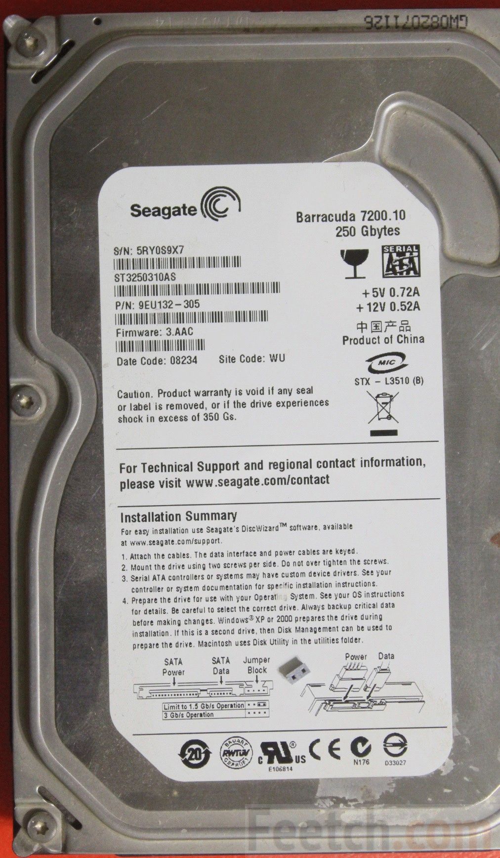
Sometimes the hard drive can contain useful information that any advanced user can understand. But sometimes the designation tends to be so ornate that only a true professional can comprehend it. As, for example, in this case.

There is information about the brand, serial number, technical data and even measures of disk capacity. But its interface remains unknown. This is important when choosing hardware for a computer with limited capabilities. If the disk had a SATA3 interface, then it is useless to install one in an old system unit. There are many other similar examples. Let's say in advance that this drive has a SATA 2.6 interface. Consequently, its information exchange rate limit is 3 Mbit/s.
If information about the HDD interface type is available
How to tell the difference? First, you can look at the body. Here is an image of an old disk that supports two speeds, therefore, it is a SATA2 device.
When removed from the system unit, it was equipped with a jumper that reduced the speed.

The jumper was immediately removed, therefore, the device will now function twice as fast. On the SATA 2.0 bus of the GA-H61M-D2-B3 motherboard.

This once again suggests that it is not enough to buy a system unit; you also need to study its entire device in general and hard drives in particular. The drives inside were paired using a special hanging frame.

This achieves better maintainability of the structure. Both hard drives were quickly removed from the case. As an alternative, a bay installation option is used, where the housing is secured with screws on both sides, and two side covers must be removed for dismantling. Which is not very convenient, considering that each of them usually jams. It is rare to find system unit cases where the sidewalls are removed using simple methods.
If HDD interface data is missing
Sometimes the hard drive may not have data transfer speed information. In this case, you can, of course, stock up on AIDA, but it’s even easier to look up the information on the Internet. The brand of the drive is determined by the price list or the appearance of the case.
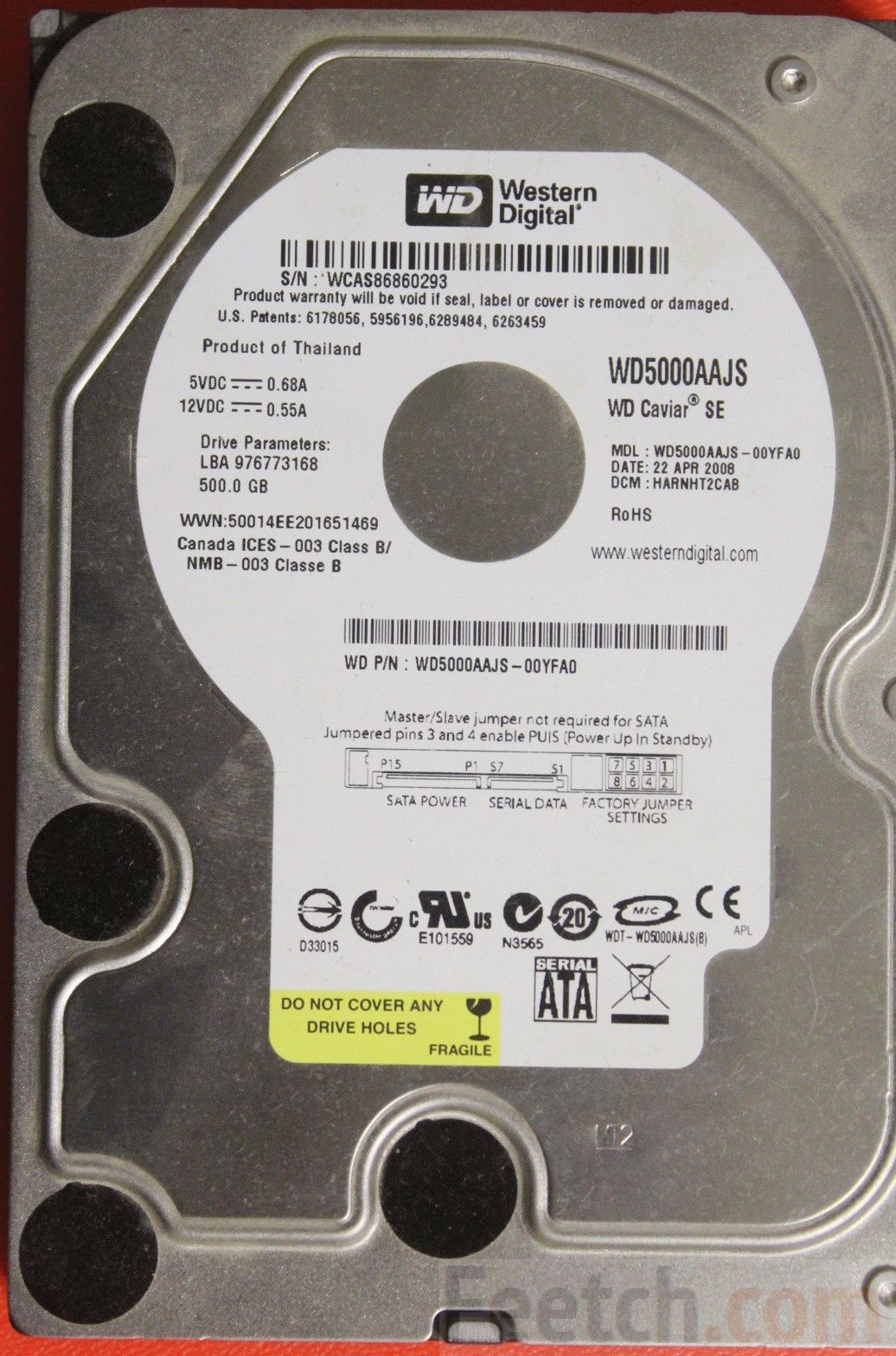
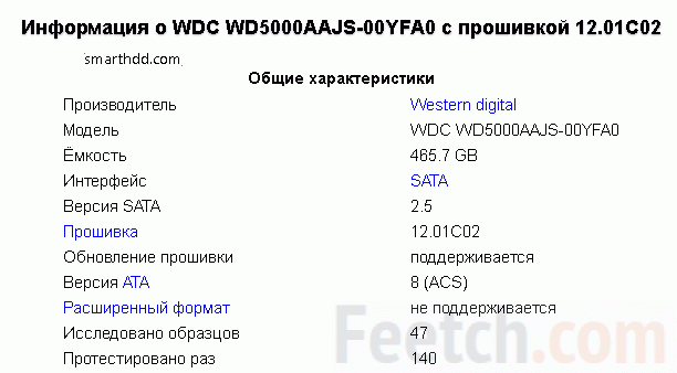
Let's say we have WD5000AAJS in our hands. Only one thing is known - at lunchtime he will be a hundred years old. Therefore, you need to familiarize yourself with historical information on the Internet. Since models are constantly updated, you need to enter the code followed by a dash - 00YFA0. The search engine quickly provided an answer, and now there is every reason to claim that the channel bandwidth is 3 Gbit/s (SATA 2.5 generation).
We have already discussed above how to connect such equipment to an outdated motherboard that does not have a SATA interface. So let's move on to new products.
Connecting SATA to exSATA bus
When engineers approached the problem of increasing SATA speeds to 12 Gbit/s and higher, it turned out that this was not economically viable. Energy efficiency drops sharply while prices rise. Someone noticed that the PCI Express graphics card bus operates at high speeds without problems, and then it was decided to make some kind of hybrid between it and the now obsolete SATA. To do this, the connector was divided into two parts:
- Specific. Small port on the side.
- Standard. Two ports for SATA0 connection.
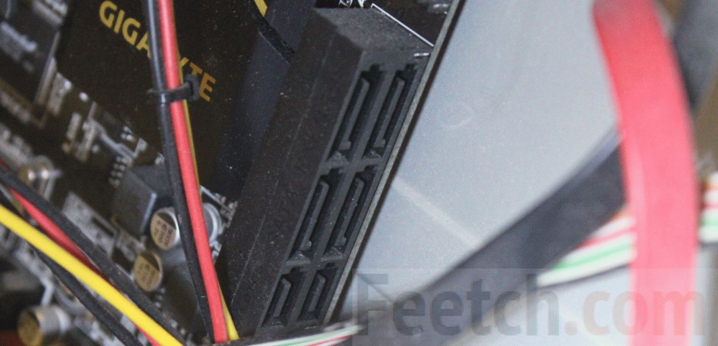
The figure shows a dual exSATA port. This can include 4 hard drives with a SATA interface, or 2 exSATA, or 1 exSATA and 2 SATA. Below is an example of connecting two SATA drives to one exSATA port.
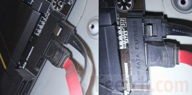
Due to its large size, covering three exSATA slots at once, the plug is called a hub among professionals. You need to start by checking the BIOS. It turned out that some motherboards can turn off SATA support, completely switching to Express, which supports speeds of up to 16 Gbps.

At the same time, you can look at the BIOS capabilities regarding RAID arrays. Let us remember that in the latter case, several hard drives can duplicate their information for reliability, or turn on alternately, which significantly increases the speed of operation. The size of the article does not allow us to speak in more detail on this topic.

The selected AHCI mode is the default mode for most systems. It provides maximum compatibility with older equipment in a completely transparent manner for the user. To safely hot-plug drives, it is recommended to set the appropriate option in the BIOS settings.

When installing a new operating system, the sequence for connecting bootable media is specified. The hard drive is not put in first place. Instead, leadership is given to a flash drive or DVD drive.
Before connecting

How to connect an IDE hard drive
On the motherboard, the IDE connector is visible from afar. You can recognize it by its characteristic slot with many contacts and a key located approximately in the center of the block.

A splitter cable is usually hung on each port, so that a master and a servant are on the channel at the same time.
Before connecting a drive, you need to correctly configure the jumpers on its case - Slave or Master. There will definitely be a diagram on the case on how to do this.

For drives from different manufacturers, the order in which jumpers are inserted will be unique (they seem to be competing in this). The disk must be a bus master, otherwise the operating system cannot be started from it (No IDE Master detected). Therefore, it is necessary to set the slave jumper on the CD drive.

After setting the jumpers, insert the hard drive into a suitable cage and secure it with four screws on both sides. Connect the single data cable connector to the corresponding header on the motherboard. Connect the power cables. The order doesn't matter here.
Now you can close the system unit covers and connect the computer. The system itself should detect new connections and configure everything. The user will only have to confirm operations in the Add New Equipment Wizard.
If the system is confused about where the Master is and where the Slave is, then you need to make assignments in the BIOS. Immediately after turning on the power, press the F2 or Del key repeatedly (in different ways) to open the BIOS settings. Find the interface for describing the order of boot devices, set the parameters. The first is the CD drive from which the system is installed. Save the settings using the F10 key. After this, the operating system will begin loading.
How to connect a SATA hard drive to an old motherboard
To connect a SATA hard drive, use a PCI bus adapter. It may have one or another number of ports; accordingly, several hard drives are installed.

Insert the card into the slot, connect the hard drive, place it in the bay and secure it with screws on both sides - two or four screws in total. It is advisable to choose the location of the modules inside the system unit in such a way that, if possible, there is enough free space between them to ensure ventilation. Otherwise, if the computer overheats, it will automatically turn off.
Now connect the power cable to the hard drive. If the power supply is an old model for IDE, you will need an adapter to connect SATA. Now you can connect the data cable to the hard drive. After the system boots, you should install the driver from the included DVD, and the new drive will become visible through Explorer.

Sometimes there is no other drive other than SATA. And then you need to install Windows again via a PCI adapter. The bootloader will not see the drive, but will give you the opportunity to find it manually. This is where you will need to find the required driver for the current operating system on the DVD. The installer will then notice the disk and you can create partitions for the new operating system. This is absolutely accurate, because the authors installed the “seven” in this way on an old system unit.
Hello dear visitors. In this lesson, I will show you using a real example how to connect a hard drive to your computer. I want to warn you right away that this is not difficult and it will not waste much of your time.
Let's get started right away!
First of all, prepare the system unit: turn off the power and disconnect all cables from it so that they do not interfere with us. After this, remove the side cover from the system unit by unscrewing the two screws on the back.

Now we can already see the insides of our computer. note to the lower right system unit. Here are the bays for connecting hard drives.

Pick up the hard drive and carefully insert it into the free slot. The main thing is that the connectors for connection are turned inside the system unit.


Here the holes in the hard drive and on the slot itself where the drive is connected must also match. We will use these holes for fixing. We take 4 bolts and fasten them on one side and the other.

Completed at this stage installing a hard drive into the system unit. Now you need to connect it to the motherboard. To do this, modern computers use a SATA power cable and a SATA interface cable. This is what they look like:

First of all, connect the SATA interface to the hard drive.

Be sure to connect the correct way. If you suddenly feel that the cable does not fit into the connector, then try connecting it on the other side. He'll definitely fit in.
The other side of the cable must be connected to the motherboard. We look for a suitable connector and connect it. Typically, these connectors are located at the bottom of the board and are labeled SATA.

The last step remains - supply power to the hard drive.
We take the SATA power cable and connect it to the hard drive, next to the first connector.

The other side of this cable must be connected to the power supply. Examine the wires coming from the power supply and find the connector for connection.

By the way, if you already have another hard drive is connected to the computer, then most likely the power is already leaving it and of course you can use it so as not to create new wires.
This is how it can hang unnoticeably among the wires:

After connecting the hard drive to the system unit, we proceed to setting it up in the system. Close the system cover and reconnect all the wires. Let's turn on the computer!
If you have a new hard drive, then most likely it will not be immediately detected by the system and you will need to format it.
Open the Computer section and see if a new hard drive has appeared?


Right-click on the Computer section and select Manage.


ATTENTION! The main thing here is not to mess anything up and not to delete data from the necessary disks!!!
Create a simple volume and format the new hard drive and, if necessary, assign a drive letter to it.


Well, as you can see, in modern computers connect hard drive very simple! It only remains to mention that in addition to the modern SATA interface, there is also IDE, which is used in old drives! It looks like this:

Now let's summarize briefly. So, to connect the hard drive to the computer you need to do the following steps:
1. Install the hard drive in a free slot
2. Connect the SATA interface
3. Connect SATA power
4. Set up a hard drive in Windows
That's all, good luck connecting the hard drive!
At the moment the most common interface is . Although SATA can be found on sale, the interface is already considered obsolete, and they have already begun to arrive with.
This should not be confused with SATA 3.0 Gbit/s; in the second case we are talking about the SATA 2 interface, which has a throughput of up to 3.0 Gbit/s (SATA 3 has a throughput of up to 6 Gbit/s)
Interface- a device that transmits and converts signals from one piece of equipment to another.
Types of interface. PATA, SATA, SATA 2, SATA 3, etc.
Drives of various generations used the following interfaces: IDE (ATA), USB, Serial ATA (SATA), SATA 2, SATA 3, SCSI, SAS, CF, EIDE, FireWire, SDIO and Fiber Channel.
IDE (ATA - Advanced Technology Attachment)- parallel interface for connecting drives, which is why it was changed (with the output SATA) on PATA(Parallel ATA). Previously used to connect hard drives, but was supplanted by the SATA interface. Currently used to connect optical drives.
SATA (Serial ATA)— serial interface for data exchange with drives. An 8-pin connector is used for connection. As is the case with PATA– is obsolete and is used only for working with optical drives. The SATA standard (SATA150) provided a throughput of 150 MB/s (1.2 Gbit/s).
SATA 2 (SATA300). The SATA 2 standard doubled the throughput, up to 300 MB/s (2.4 Gbit/s), and allows operation at a frequency of 3 GHz. Standard SATA and SATA 2 are compatible with each other, but for some models it is necessary to manually set the modes by rearranging the jumpers.
Although it is correct to say about the requirement of specifications SATA 6Gb/s. This standard doubled the data transfer speed to 6 Gbit/s (600 MB/s). Other positive innovations include the NCQ program control function and commands for continuous data transfer for a high-priority process.
Although the interface was introduced in 2009, it is not yet particularly popular among manufacturers and is not often found in stores. In addition to hard drives, this standard is used in SSDs (solid-state drives).
It is worth noting that in practice the bandwidth of SATA interfaces does not differ in data transfer speed. In practice, the speed of writing and reading disks does not exceed 100 MB/s. Increasing the indicators only affects the throughput between the controller and the drive.
SCSI(Small Computer System Interface)— the standard is used in servers where increased data transfer speed is required.
SAS (Serial Attached SCSI)- the generation that replaced the SCSI standard, using serial data transmission. Like SCSI, it is used in workstations. Fully compatible with the SATA interface.
CF (Compact Flash)— Interface for connecting memory cards, as well as for 1.0 inch hard drives. There are 2 standards: Compact Flash Type I and Compact Flash Type II, the difference is in thickness.
FireWire– an alternative interface to the slower USB 2.0. Used to connect portable . Supports speeds up to 400 Mb/s, but the physical speed is lower than regular ones. When reading and writing, the maximum threshold is 40 MB/s.
SATA (English: Serial ATA)- serial interface for data exchange with information storage devices. SATA is a development of the parallel interface, which after the advent of SATA was renamed PATA (Parallel ATA). - data cable connector. Hard drive data cable connector -
Description SATA
SATA uses a 7-pin connector instead of PATA's 40-pin connector. The SATA cable has a smaller area, due to which the resistance to air blowing through the computer components is reduced, and wiring inside the system unit is simplified.
Due to its shape, the SATA cable is more resistant to multiple connections. The SATA power cord is also designed to accommodate multiple connections. The SATA power connector supplies 3 supply voltages: +12 V, +5 V and +3.3 V; however, modern devices can operate without +3.3 V, which makes it possible to use a passive adapter from a standard IDE to SATA power connector. A number of SATA devices come with two power connectors: SATA and Molex.
The SATA standard abandoned the traditional PATA connection of two devices per cable; each device is assigned a separate cable, which eliminates the problem of the impossibility of simultaneous operation of devices located on the same cable (and the delays that arise from this), reduces possible problems during assembly (there is no problem of conflict between Slave/Master devices for SATA), eliminates the possibility of errors when using non-terminated PATA- loops.
The SATA standard supports the command queuing function (NCQ, starting with SATA Revision 2.x).
The SATA standard does not provide for hot-swapping of the active device (used by the Operating System) (up to SATA Revision 3.x), additionally connected drives must be disconnected gradually - power, cable, and connected in the reverse order - cable, power.
SATA connectors
SATA devices use two connectors: 7-pin (data bus connection) and 15-pin (power connection). The SATA standard provides the ability to use a standard 4-pin Molex connector instead of a 15-pin power connector. Using both types of power connectors at the same time may damage the device.
The SATA interface has two data transfer channels, from controller to device and from device to controller. LVDS technology is used for signal transmission; the wires of each pair are shielded twisted pairs.
There is also a 13-pin combined SATA connector used in servers, mobile and portable devices for slim CD/DVD drives. Devices are connected using a SATA Slimline ALL-in-One Cable. It consists of a combined connector of a 7-pin connector for connecting the data bus and a 6-pin connector for connecting the device’s power supply. In addition, to connect to these devices, servers use a special adapter.
Using http://ru.wikipedia.org/wiki/SATA
The most interesting comments on the colors of the SATA power connector cable:
RU2012:"Adapters are available to convert a 4-pin Molex connector to a SATA power connector. However, since 4-pin Molex connectors do not provide 3.3 V, these adapters only provide 5 V and 12 V power and leave the 3.3 V lines disabled. This does not allow the use of such adapters with drives that require 3.3 V power - orange wire.
Recognizing this, hard drive manufacturers have largely left support for the 3.3V orange power cable option in their storage devices - power lines are not used in most devices.
HOWEVER, WITHOUT 3.3V POWER (orange wire), the SATA DEVICE MAY NOT BE ABLE TO HOT PLUG THE DISK..." - http://en.wikipedia.org/wiki/Serial_ATA
Have questions - ask- we will help as best we can (for comments to work, you need to have the Java script enabled in your browser):
To comment, just ask a question in the window below, then click “Post as” - enter your email and Name, and click “Post comment”.
The system unit case has compartments for devices (usually they are located in the front part of the case). The upper compartments of the case are usually designed for installing optical drives CD/DVD, Blu-Ray. And the lower compartments shown in the photo are designed for installing hard drives.
We select any of the available compartments and place the hard drive there. It is necessary to position it so that the connectors (see image) of the drive face inside the case.

Then, we take the hard drive and insert it along the guides that prevent it from falling down.

All. The disk is inserted, now it needs to be secured with screws. As you can see, the case has corresponding mounting holes.

It is necessary to ensure that the threaded holes on the disk match the holes on the body. Now we will tighten the screws in them.

It is desirable that there are four screws, two on one side and two on the other. Having screwed the hard drive on one side, unfold the case and screw the other side.

We have secured the hard drive. Check that it does not wobble; if the disk moves, then tighten the screws more tightly.

The hard drive installation is complete and you can now connect it to the motherboard. First of all, you should take into account that hard drives of different generations have different connectors and different cables (“cables”) for connection.
We will look at connecting a hard drive with the most common interfaces IDE (outdated, but still in use) and SATA.
Connecting a hard drive with a SATA interface
The SATA hard drive is connected using a narrow data cable shown in the figure.

We connect one end of this cable to the connector on the disk, and the other to the motherboard.

After connecting the data cable, connect the power cable (from the power supply) to the corresponding connector of the SATA drive

If your power supply does not have connectors for SATA devices, use an IDE/SATA power adapter. If the hard drive has two types of power connectors, SATA and MOLEX, connecting one of them is enough.
All. We have a hard drive with a SATA interface connected.

How to connect a hard drive via SATA video:
Connecting an IDE hard drive
When connecting an IDE disk, first of all you need to set its operating mode: MASTER (master) or SLAVE (slave). Since we are installing one hard drive, we need to set the MASTER mode. The mode is determined by the position of the jumper on the back of the disk.

The figure on top of the hard drive shows which position to install the jumper to make it work as MASTER.
This is what the IDE connectors on the motherboard look like for connecting IDE drives and other IDE devices.

Devices are connected using an IDE cable (cable).

We take the end of a longer segment of the cable and connect it to the connector on the motherboard. Since we have one hard drive, the cable should be connected to the first IDE channel (on the motherboard there is usually a designation - IDE 0 Primary and IDE 1 Secondary).

Now we connect the cable to the hard drive. The connector located at the end of a short section of the cable is always connected to MASTER.
That's all. We took a step-by-step look at how to correctly connect a new hard drive via SATA, as well as a hard drive with an old IDE connector. By following these instructions, you can also additionally connect a second hard drive to your computer. If the hard drive is new or transferred from another computer, then the following all necessary procedures for setting it up will be performed during.


