2 serial and parallel connection of conductors. Parallel connection of conductors
Usually everyone finds it difficult to answer. But this riddle, when applied to electricity, is solved quite definitely.
Electricity begins with Ohm's law.
And if we consider the dilemma in the context of parallel or serial connections - considering one connection to be a chicken and the other to be an egg, then there is no doubt at all.
Because Ohm's law is the very original electrical circuit. And it can only be consistent.
Yes, they came up with a galvanic cell and didn’t know what to do with it, so they immediately came up with another light bulb. And this is what came out of it. Here, a voltage of 1.5 V immediately flowed as current, in strict compliance with Ohm's law, through the light bulb to the back of the same battery. And inside the battery itself, under the influence of the sorceress-chemistry, the charges again ended up at the original point of their journey. And therefore, where the voltage was 1.5 volts, it remains that way. That is, the voltage is always the same, and the charges are constantly moving and successively pass through the light bulb and the galvanic cell.
And it is usually drawn on the diagram like this:

According to Ohm's law I=U/R
Then the resistance of the light bulb (with the current and voltage that I wrote) will be
R= 1/U, WhereR = 1 Ohm
And the power will be released P = I * U , that is, P=2.25 Vm
In a series circuit, especially with such a simple and undeniable example, it is clear that the current that runs through it from beginning to end is the same all the time. And if we now take two light bulbs and make sure that the current runs first through one and then through the other, then the same thing will happen again - the current will be the same in both the light bulb and the other. Although different in size. The current now experiences the resistance of two light bulbs, but each of them has the same resistance as it was, and remains the same, because it is determined solely by the physical properties of the light bulb itself. We calculate the new current again using Ohm's law.

It will turn out to be equal to I=U/R+R, that is, 0.75A, exactly half of the current that was at first.
In this case, the current has to overcome two resistances, it becomes smaller. As can be seen from the glow of the light bulbs - they are now burning at full intensity. And the total resistance of a chain of two light bulbs will be equal to the sum of their resistances. Knowing arithmetic, in a particular case you can use the action of multiplication: if N identical light bulbs are connected in series, then their total resistance will be equal to N multiplied by R, where R is the resistance of one light bulb. The logic is impeccable.

And we will continue our experiments. Now let's do something similar to what we did with light bulbs, but only on the left side of the circuit: add another galvanic element, exactly the same as the first. As you can see, now our total voltage has doubled, and the current has returned to 1.5 A, which is signaled by the light bulbs, which light up again at full power.
We conclude:
- When an electrical circuit is connected in series, the resistances and voltages of its elements are summed up, and the current on all elements remains unchanged.
It is easy to verify that this statement is true for both active components (galvanic cells) and passive ones (light bulbs, resistors).
That is, this means that the voltage measured across one resistor (it is called the voltage drop) can be safely summed up with the voltage measured across another resistor, and the total will be the same 3 V. And at each of the resistances it will be equal to half - then there is 1.5 V. And this is fair. Two galvanic cells produce their voltages, and two light bulbs consume them. Because in a voltage source, the energy of chemical processes is converted into electricity, which takes the form of voltage, and in light bulbs the same energy is converted from electrical into heat and light.
Let's return to the first circuit, connect another light bulb in it, but differently.
Now the voltage at the points connecting the two branches is the same as on the galvanic element - 1.5 V. But since the resistance of both bulbs is also the same as it was, the current through each of them will flow 1.5 A - "full glow" current.

The galvanic cell now supplies them with current at the same time, therefore, both of these currents flow out of it at once. That is, the total current from the voltage source will be 1.5 A + 1.5 A = 3.0 A.
What is the difference between this circuit and the circuit when the same light bulbs were connected in series? Only in the glow of light bulbs, that is, only in current.
Then the current was 0.75 A, but now it is immediately 3 A.
It turns out that if we compare it with the original circuit, then when connecting the light bulbs in series (scheme 2), there was more resistance to the current (which is why it decreased, and the light bulbs lost their luminosity), and a parallel connection has LESS resistance, although the resistance of the light bulbs remained unchanged. What's the matter?
But the fact is that we forget one interesting truth, that every sword is a double-edged sword.
When we say that a resistor resists current, we seem to forget that it still conducts current. And now that the light bulbs have been connected in parallel, their overall ability to conduct current rather than resist it has increased. Well, and, accordingly, a certain amount G, by analogy with resistance R and should be called conductivity. And it must be summed up in a parallel connection of conductors.
Well here she is
Ohm's law will then look like
I = U* G&
And in the case of a parallel connection, the current I will be equal to U*(G+G) = 2*U*G, which is exactly what we observe.
Replacement of circuit elements with a common equivalent element
Engineers often need to recognize currents and voltages in all parts of circuits. But real electrical circuits can be quite complex and branched and can contain many elements that actively consume electricity and are connected to each other in completely different combinations. This is called electrical circuit calculation. It is done when designing the energy supply of houses, apartments, and organizations. In this case, it is very important what currents and voltages will act in the electrical circuit, if only in order to select appropriate wire sections, loads on the entire network or its parts, and so on. And I think everyone understands how complex electronic circuits are, containing thousands or even millions of elements.
The very first thing that suggests itself is to use the knowledge of how voltage currents behave in such simple network connections as serial and parallel. They do this: instead of a serial connection found on the network of two or more active consumer devices (like our light bulbs), draw one, but so that its resistance is the same as both. Then the picture of currents and voltages in the rest of the circuit will not change. Similarly with parallel connections: instead of them, draw an element whose CONDUCTIVITY would be the same as both.
Now, if we redraw the circuit, replacing the serial and parallel connections with one element, we will get a circuit called an “equivalent equivalent circuit.”
This procedure can be continued until we are left with the simplest one - with which we illustrated Ohm’s law at the very beginning. Only instead of the light bulb there will be one resistance, which is called the equivalent load resistance.
This is the first task. It allows us to use Ohm's law to calculate the total current in the entire network, or the total load current.
This is a complete calculation of the electrical network.
Examples
Let the circuit contain 9 active resistances. It could be light bulbs or something else.
A voltage of 60 V is applied to its input terminals.

The resistance values for all elements are as follows:
Find all unknown currents and voltages.
It is necessary to follow the path of searching for parallel and serial sections of the network, calculating their equivalent resistances and gradually simplifying the circuit. We see that R 3, R 9 and R 6 are connected in series. Then their equivalent resistance R e 3, 6, 9 will be equal to their sum R e 3, 6, 9 = 1 + 4 + 1 Ohm = 6 Ohm.

Now we replace the parallel piece of resistance R 8 and R e 3, 6, 9, getting R e 8, 3, 6, 9. Only when connecting conductors in parallel will the conductivity have to be added.
Conductivity is measured in units called siemens, the reciprocal of ohms.
If we turn the fraction over, we get resistance R e 8, 3, 6, 9 = 2 Ohm
Exactly the same as in the first case, we combine resistances R 2, R e 8, 3, 6, 9 and R 5 connected in series, obtaining R e 2, 8, 3, 6, 9, 5 = 1 + 2 + 1 = 4 Ohm.
There are two steps left: obtain a resistance equivalent to two resistors for parallel connection of conductors R 7 and R e 2, 8, 3, 6, 9, 5.
It is equal to R e 7, 2, 8, 3, 6, 9, 5 = 1/(1/4+1/4)=1/(2/4)=4/2 = 2 Ohm

At the last step, we sum up all series-connected resistances R 1, R e 7, 2, 8, 3, 6, 9, 5 and R 4 and obtain a resistance equivalent to the resistance of the entire circuit R e and equal to the sum of these three resistances
R e = R 1 + R e 7, 2, 8, 3, 6, 9, 5 + R4 = 1 + 2 + 1 = 4 Ohm
Well, let’s remember in whose honor the unit of resistance we wrote in the last of these formulas was named, and use his law to calculate the total current in the entire circuit I
![]()

Now, moving in the opposite direction, towards increasing complexity of the network, we can obtain currents and voltages in all chains of our fairly simple circuit according to Ohm’s law.
This is how apartment power supply schemes are usually calculated, which consist of parallel and serial sections. Which, as a rule, is not suitable in electronics, because a lot of things work there differently, and everything is much more intricate. And such a circuit, for example, when you don’t understand whether the connection of conductors is parallel or serial, is calculated according to Kirchhoff’s laws.
The flow of current in an electrical circuit is carried out through conductors, in the direction from the source to the consumers. Most of these circuits use copper wires and electrical receivers in a given quantity, having different resistances. Depending on the tasks performed, electrical circuits use serial and parallel connections of conductors. In some cases, both types of connections can be used, then this option will be called mixed. Each circuit has its own characteristics and differences, so they must be taken into account in advance when designing circuits, repairing and servicing electrical equipment.
Series connection of conductors
In electrical engineering, the series and parallel connection of conductors in an electrical circuit is of great importance. Among them, a series connection scheme of conductors is often used, which assumes the same connection of consumers. In this case, inclusion in the circuit is performed one after another in order of priority. That is, the beginning of one consumer is connected to the end of another using wires, without any branches.
The properties of such an electrical circuit can be considered using the example of sections of a circuit with two loads. The current, voltage and resistance on each of them should be designated respectively as I1, U1, R1 and I2, U2, R2. As a result, relations were obtained that express the relationship between quantities as follows: I = I1 = I2, U = U1 + U2, R = R1 + R2. The data obtained are confirmed in practice by taking measurements with an ammeter and a voltmeter of the corresponding sections.
Thus, the series connection of conductors has the following individual features:
- The current strength in all parts of the circuit will be the same.
- The total voltage of the circuit is the sum of the voltages in each section.
- The total resistance includes the resistance of each individual conductor.
These ratios are suitable for any number of conductors connected in series. The total resistance value is always higher than the resistance of any individual conductor. This is due to an increase in their total length when connected in series, which also leads to an increase in resistance.

If you connect identical elements in series n, you get R = n x R1, where R is the total resistance, R1 is the resistance of one element, and n is the number of elements. Voltage U, on the contrary, is divided into equal parts, each of which is n times less than the total value. For example, if 10 lamps of the same power are connected in series to a network with a voltage of 220 volts, then the voltage in any of them will be: U1 = U/10 = 22 volts.
Conductors connected in series have a characteristic distinctive feature. If at least one of them fails during operation, the current flow stops in the entire circuit. The most striking example is when one burnt-out light bulb in a series circuit leads to failure of the entire system. To identify a burnt out light bulb, you will need to check the entire garland.
Parallel connection of conductors
In electrical networks, conductors can be connected in various ways: in series, in parallel and in combination. Among them, a parallel connection is an option when the conductors at the starting and ending points are connected to each other. Thus, the beginnings and ends of the loads are connected together, and the loads themselves are located parallel to each other. An electrical circuit may contain two, three or more conductors connected in parallel.

If we consider a series and parallel connection, the current strength in the latter can be studied using the following circuit. Take two incandescent lamps that have the same resistance and are connected in parallel. For control, each light bulb is connected to its own. In addition, another ammeter is used to monitor the total current in the circuit. The test circuit is supplemented by a power source and a key.
After closing the key, you need to monitor the readings of the measuring instruments. The ammeter on lamp No. 1 will show the current I1, and on lamp No. 2 the current I2. The general ammeter shows the current value equal to the sum of the currents of individual, parallel-connected circuits: I = I1 + I2. Unlike a series connection, if one of the bulbs burns out, the other will function normally. Therefore, parallel connection of devices is used in home electrical networks.
Using the same circuit, you can set the value of the equivalent resistance. For this purpose, a voltmeter is added to the electrical circuit. This allows you to measure the voltage in a parallel connection, while the current remains the same. There are also crossing points for the conductors connecting both lamps.

As a result of measurements, the total voltage for a parallel connection will be: U = U1 = U2. After this, you can calculate the equivalent resistance, which conditionally replaces all the elements in a given circuit. With a parallel connection, in accordance with Ohm's law I = U/R, the following formula is obtained: U/R = U1/R1 + U2/R2, in which R is the equivalent resistance, R1 and R2 are the resistances of both bulbs, U = U1 = U2 is the voltage value shown by the voltmeter.
One should also take into account the fact that the currents in each circuit add up to the total current strength of the entire circuit. In its final form, the formula reflecting the equivalent resistance will look like this: 1/R = 1/R1 + 1/R2. As the number of elements in such chains increases, the number of terms in the formula also increases. The difference in basic parameters distinguishes current sources from each other, allowing them to be used in various electrical circuits.
A parallel connection of conductors is characterized by a fairly low equivalent resistance value, so the current strength will be relatively high. This factor should be taken into account when a large number of electrical appliances are plugged into sockets. In this case, the current increases significantly, leading to overheating of cable lines and subsequent fires.
Laws of series and parallel connection of conductors
These laws concerning both types of conductor connections have been partially discussed earlier.

For a clearer understanding and perception in a practical sense, series and parallel connection of conductors, formulas should be considered in a certain sequence:
- A series connection assumes the same current in each conductor: I = I1 = I2.
- Parallel and series connection of conductors is explained in each case differently. For example, with a series connection, the voltages on all conductors will be equal to each other: U1 = IR1, U2 = IR2. In addition, with a series connection, the voltage is the sum of the voltages of each conductor: U = U1 + U2 = I(R1 + R2) = IR.
- The total resistance of a circuit in a series connection consists of the sum of the resistances of all individual conductors, regardless of their number.
- With a parallel connection, the voltage of the entire circuit is equal to the voltage on each of the conductors: U1 = U2 = U.
- The total current measured in the entire circuit is equal to the sum of the currents flowing through all conductors connected in parallel: I = I1 + I2.
In order to more effectively design electrical networks, you need to have a good knowledge of the series and parallel connection of conductors and its laws, finding the most rational practical application for them.
Mixed connection of conductors
Electrical networks typically use serial parallel and mixed connections of conductors designed for specific operating conditions. However, most often preference is given to the third option, which is a set of combinations consisting of various types of compounds.

In such mixed circuits, serial and parallel connections of conductors are actively used, the pros and cons of which must be taken into account when designing electrical networks. These connections consist not only of individual resistors, but also rather complex sections that include many elements.
The mixed connection is calculated according to the known properties of series and parallel connections. The calculation method consists of breaking the circuit down into simpler components, which are calculated separately and then summed up with each other.
Series, parallel and mixed connections of resistors. A significant number of receivers included in the electrical circuit (electric lamps, electric heating devices, etc.) can be considered as some elements that have a certain resistance. This circumstance gives us the opportunity, when drawing up and studying electrical circuits, to replace specific receivers with resistors with certain resistances. There are the following methods resistor connections(receivers of electrical energy): serial, parallel and mixed.
Series connection of resistors.
For serial connection several resistors, the end of the first resistor is connected to the beginning of the second, the end of the second to the beginning of the third, etc. With this connection, all elements of the series circuit pass
the same current I.
The serial connection of receivers is illustrated in Fig. 25, a.
.Replacing the lamps with resistors with resistances R1, R2 and R3, we get the circuit shown in Fig. 25, b.
If we assume that Ro = 0 in the source, then for three series-connected resistors, according to Kirchhoff’s second law, we can write:
E = IR 1 + IR 2 + IR 3 = I(R 1 + R 2 + R 3) = IR eq (19)
Where R eq =R 1 + R 2 + R 3.
Consequently, the equivalent resistance of a series circuit is equal to the sum of the resistances of all series-connected resistors. Since the voltages in individual sections of the circuit are according to Ohm’s law: U 1 =IR 1 ; U 2 = IR 2, U 3 = IR з and in this case E = U, then for the circuit under consideration
U = U 1 + U 2 + U 3 (20)
Consequently, the voltage U at the source terminals is equal to the sum of the voltages at each of the series-connected resistors.
From these formulas it also follows that the voltages are distributed between series-connected resistors in proportion to their resistances:
U 1: U 2: U 3 = R 1: R 2: R 3 (21)
that is, the greater the resistance of any receiver in a series circuit, the greater the voltage applied to it.
If several, for example n, resistors with the same resistance R1 are connected in series, the equivalent resistance of the circuit Rek will be n times greater than the resistance R1, i.e. Rek = nR1. The voltage U1 on each resistor in this case is n times less than the total voltage U:
When receivers are connected in series, a change in the resistance of one of them immediately entails a change in the voltage at the other receivers connected to it. When the electrical circuit is turned off or broken, the current in one of the receivers and in the remaining receivers stops. Therefore, series connection of receivers is rarely used - only in the case when the voltage of the electrical energy source is greater than the rated voltage for which the consumer is designed. For example, the voltage in the electrical network from which subway cars are powered is 825 V, while the nominal voltage of the electric lamps used in these cars is 55 V. Therefore, in subway cars, electric lamps are switched on in series, 15 lamps in each circuit.
Parallel connection of resistors. In parallel connection several receivers, they are connected between two points of the electrical circuit, forming parallel branches (Fig. 26, a). Replacing
lamps with resistors with resistances R1, R2, R3, we get the circuit shown in Fig. 26, b.
When connected in parallel, the same voltage U is applied to all resistors. Therefore, according to Ohm’s law:
I 1 =U/R 1; I 2 =U/R 2 ; I 3 =U/R 3.
Current in the unbranched part of the circuit according to Kirchhoff’s first law I = I 1 +I 2 +I 3, or
I = U / R 1 + U / R 2 + U / R 3 = U (1/R 1 + 1/R 2 + 1/R 3) = U / R eq (23)
Therefore, the equivalent resistance of the circuit under consideration when three resistors are connected in parallel is determined by the formula
1/R eq = 1/R 1 + 1/R 2 + 1/R 3 (24)
By introducing into formula (24) instead of the values 1/R eq, 1/R 1, 1/R 2 and 1/R 3 the corresponding conductivities G eq, G 1, G 2 and G 3, we obtain: the equivalent conductance of a parallel circuit is equal to the sum of the conductances of parallel connected resistors:
G eq = G 1 + G 2 + G 3 (25)
Thus, as the number of resistors connected in parallel increases, the resulting conductivity of the electrical circuit increases, and the resulting resistance decreases.
From the above formulas it follows that currents are distributed between parallel branches in inverse proportion to their electrical resistance or directly proportional to their conductivity. For example, with three branches
I 1: I 2: I 3 = 1/R 1: 1/R 2: 1/R 3 = G 1 + G 2 + G 3 (26)
In this regard, there is a complete analogy between the distribution of currents along individual branches and the distribution of water flows through pipes.
The given formulas make it possible to determine the equivalent circuit resistance for various specific cases. For example, with two resistors connected in parallel, the resulting circuit resistance is
R eq =R 1 R 2 /(R 1 +R 2)
with three resistors connected in parallel
R eq =R 1 R 2 R 3 /(R 1 R 2 +R 2 R 3 +R 1 R 3)
When several, for example n, resistors with the same resistance R1 are connected in parallel, the resulting circuit resistance Rec will be n times less than the resistance R1, i.e.
R eq = R1/n(27)
The current I1 passing through each branch, in this case, will be n times less than the total current:
I1 = I/n (28)
When the receivers are connected in parallel, they are all under the same voltage, and the operating mode of each of them does not depend on the others. This means that the current passing through any of the receivers will not have a significant effect on the other receivers. Whenever any receiver is turned off or fails, the remaining receivers remain on.
valuable. Therefore, a parallel connection has significant advantages over a serial connection, as a result of which it is most widely used. In particular, electric lamps and motors designed to operate at a certain (rated) voltage are always connected in parallel.
On DC electric locomotives and some diesel locomotives, traction motors must be switched on at different voltages during speed control, so they switch from a series connection to a parallel connection during acceleration.
Mixed connection of resistors. Mixed compound This is a connection in which some of the resistors are connected in series, and some in parallel. For example, in the diagram of Fig. 27, and there are two series-connected resistors with resistances R1 and R2, a resistor with resistance R3 is connected in parallel with them, and a resistor with resistance R4 is connected in series with a group of resistors with resistances R1, R2 and R3.
The equivalent resistance of a circuit in a mixed connection is usually determined by the conversion method, in which a complex circuit is converted into a simple one in successive steps. For example, for the diagram in Fig. 27, and first determine the equivalent resistance R12 of series-connected resistors with resistances R1 and R2: R12 = R1 + R2. In this case, the diagram in Fig. 27, and is replaced by the equivalent circuit of Fig. 27, b. Then the equivalent resistance R123 of parallel-connected resistances and R3 are determined using the formula
R 123 = R 12 R 3 / (R 12 + R 3) = (R 1 + R 2) R 3 / (R 1 + R 2 + R 3).
In this case, the diagram in Fig. 27, b is replaced by the equivalent circuit of Fig. 27, v. After this, the equivalent resistance of the entire circuit is found by summing the resistance R123 and the resistance R4 connected in series with it:
R eq = R 123 + R 4 = (R 1 + R 2) R 3 / (R 1 + R 2 + R 3) + R 4
Series, parallel and mixed connections are widely used to change the resistance of starting rheostats when starting an electric power plant. p.s. direct current.
The current in an electrical circuit passes through conductors from the voltage source to the load, that is, to lamps and devices. In most cases, copper wires are used as conductors. The circuit may contain several elements with different resistances. In an instrument circuit, conductors can be connected in parallel or in series, and there can also be mixed types.
A circuit element with resistance is called a resistor; the voltage of this element is the potential difference between the ends of the resistor. Parallel and series electrical connections of conductors are characterized by a single operating principle, according to which the current flows from plus to minus, and the potential decreases accordingly. In electrical circuits, the wiring resistance is taken as 0, since it is negligibly low.
A parallel connection assumes that the elements of the circuit are connected to the source in parallel and are turned on simultaneously. Series connection means that the resistance conductors are connected in strict sequence one after another.
When calculating, the idealization method is used, which greatly simplifies understanding. In fact, in electrical circuits, the potential gradually decreases as it moves through the wiring and elements that are included in a parallel or series connection.
Series connection of conductors
The serial connection scheme means that they are switched on in a certain sequence, one after the other. Moreover, the current strength in all of them is equal. These elements create a total stress in the area. Charges do not accumulate in the nodes of the electrical circuit, since otherwise a change in voltage and current would be observed. With a constant voltage, the current is determined by the value of the circuit resistance, so in a series circuit, the resistance changes if one load changes.

The disadvantage of this scheme is the fact that if one element fails, the others also lose the ability to function, since the circuit is broken. An example would be a garland that does not work if one bulb burns out. This is a key difference from a parallel connection, in which the elements can operate separately.
The sequential circuit assumes that, due to the single-level connection of the conductors, their resistance is equal at any point in the network. The total resistance is equal to the sum of the voltage reduction of individual network elements.
With this type of connection, the beginning of one conductor is connected to the end of another. The key feature of the connection is that all the conductors are on one wire without branches, and one electric current flows through each of them. However, the total voltage is equal to the sum of the voltages on each. You can also look at the connection from another point of view - all conductors are replaced by one equivalent resistor, and the current on it coincides with the total current that passes through all resistors. The equivalent cumulative voltage is the sum of the voltage values across each resistor. This is how the potential difference across the resistor appears.
Using a daisy chain connection is useful when you need to specifically turn a specific device on and off. For example, an electric bell can ring only when there is a connection to a voltage source and a button. The first rule states that if there is no current on at least one of the elements of the circuit, then there will be no current on the rest. Accordingly, if there is current in one conductor, it is also in the others. Another example would be a battery-powered flashlight, which only lights up if there is a battery, a working light bulb, and a button pressed.
In some cases, a sequential circuit is not practical. In an apartment where the lighting system consists of many lamps, sconces, chandeliers, you should not organize a scheme of this type, since there is no need to turn the lighting on and off in all rooms at the same time. For this purpose, it is better to use a parallel connection in order to be able to turn on the light in individual rooms.
Parallel connection of conductors
In a parallel circuit, the conductors are a set of resistors, some ends of which are assembled into one node, and the other ends into a second node. It is assumed that the voltage in the parallel type of connection is the same in all sections of the circuit. Parallel sections of the electrical circuit are called branches and pass between two connecting nodes; they have the same voltage. This voltage is equal to the value on each conductor. The sum of the inverse indicators of the resistances of the branches is also the inverse with respect to the resistance of an individual section of the circuit of the parallel circuit.

For parallel and series connections, the system for calculating the resistance of individual conductors is different. In the case of a parallel circuit, the current flows through the branches, which increases the conductivity of the circuit and reduces the total resistance. When several resistors with similar values are connected in parallel, the total resistance of such an electrical circuit will be less than one resistor a number of times equal to .
Each branch has one resistor, and the electric current, when it reaches the branching point, is divided and diverges to each resistor, its final value is equal to the sum of the currents at all resistances. All resistors are replaced with one equivalent resistor. Applying Ohm's law, the value of resistance becomes clear - in a parallel circuit, the values inverse to the resistances on the resistors are summed up.
With this circuit, the current value is inversely proportional to the resistance value. The currents in the resistors are not interconnected, so if one of them is turned off, this will in no way affect the others. For this reason, this circuit is used in many devices.
When considering the possibilities of using a parallel circuit in everyday life, it is advisable to note the apartment lighting system. All lamps and chandeliers must be connected in parallel; in this case, turning one of them on and off does not affect the operation of the remaining lamps. Thus, by adding a switch for each light bulb in a branch of the circuit, you can turn the corresponding light on and off as needed. All other lamps operate independently.
All electrical appliances are connected in parallel into an electrical network with a voltage of 220 V, then they are connected to. That is, all devices are connected regardless of the connection of other devices.
Laws of series and parallel connection of conductors
For a detailed understanding in practice of both types of connections, we present formulas explaining the laws of these types of connections. Power calculations for parallel and series connections are different.
In a series circuit, there is the same current in all conductors:
According to Ohm's law, these types of conductor connections are explained differently in different cases. So, in the case of a series circuit, the voltages are equal to each other:
U1 = IR1, U2 = IR2.
In addition, the total voltage is equal to the sum of the voltages of the individual conductors:
U = U1 + U2 = I(R1 + R2) = IR.
The total resistance of an electrical circuit is calculated as the sum of the active resistances of all conductors, regardless of their number.
In the case of a parallel circuit, the total voltage of the circuit is similar to the voltage of the individual elements:
And the total strength of the electric current is calculated as the sum of the currents that exist in all conductors located in parallel:
To ensure maximum efficiency of electrical networks, it is necessary to understand the essence of both types of connections and apply them expediently, using the laws and calculating the rationality of practical implementation.
Mixed connection of conductors
Series and parallel resistance circuits can be combined in one electrical circuit if necessary. For example, it is allowed to connect parallel resistors in series or in a group of resistors; this type is considered combined or mixed.

In this case, the total resistance is calculated by summing the values for the parallel connection in the system and for the series connection. First, it is necessary to calculate the equivalent resistances of resistors in a series circuit, and then the elements of a parallel circuit. Serial connection is considered a priority, and circuits of this combined type are often used in household appliances and appliances.
So, by considering the types of conductor connections in electrical circuits and based on the laws of their functioning, you can fully understand the essence of the organization of circuits of most household electrical appliances. For parallel and series connections, the calculation of resistance and current is different. Knowing the principles of calculation and formulas, you can competently use each type of circuit organization to connect elements in the optimal way and with maximum efficiency.
When solving problems, it is customary to transform the circuit so that it is as simple as possible. To do this, equivalent transformations are used. Equivalent are those transformations of a part of an electrical circuit circuit in which the currents and voltages in the non-transformed part remain unchanged.
There are four main types of conductor connections: series, parallel, mixed and bridge.
Serial connection
Serial connection- this is a connection in which the current strength throughout the entire circuit is the same. A striking example of a series connection is an old Christmas tree garland. There the light bulbs are connected in series, one after another. Now imagine one light bulb burns out, the circuit is broken and the rest of the light bulbs go out. The failure of one element leads to the shutdown of all the others; this is a significant disadvantage of a serial connection.
When connected in series, the resistances of the elements are summed up.

Parallel connection
Parallel connection- this is a connection in which the voltage at the ends of the circuit section is the same. Parallel connection is the most common, mainly because all the elements are under the same voltage, the current is distributed differently and when one of the elements exits, all the others continue to work.

In a parallel connection, the equivalent resistance is found as:
In the case of two parallel connected resistors 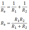
In the case of three resistors connected in parallel:


Mixed connection
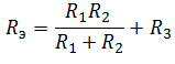
Mixed connection– a connection, which is a collection of serial and parallel connections. To find the equivalent resistance, you need to “collapse” the circuit by alternately transforming parallel and serial sections of the circuit.

First, let's find the equivalent resistance for the parallel section of the circuit, and then add to it the remaining resistance R 3 . It should be understood that after the conversion, the equivalent resistance R 1 R 2 and resistor R 3 are connected in series.
So, that leaves the most interesting and most complex connection of conductors.
Bridge circuit
The bridge connection diagram is shown in the figure below.

In order to collapse the bridge circuit, one of the bridge triangles is replaced with an equivalent star.

And find the resistances R 1, R 2 and R 3.


