Boost converter for solar battery. Stabilized voltage converter on the YX8018 chip. Network type converter
Poonam Deshpande
Electronic Design
A simple combination of a solar battery, several LEDs and a small DC/DC regulator will allow you to illuminate dark corners of the room during the daytime and at the same time provide stabilized power to low-power loads
A solar-powered lamp that only runs during the daytime may seem virtually useless, but there are many areas of homes and offices that remain relatively dark even during the day. This “daylight” glows from a nearby solar panel, and in addition has an additional stabilized 0.5 W source capable of powering small loads such as a VHF receiver.
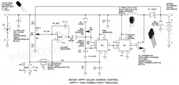
A photovoltaic panel with a nominal power of 10 W is used to power the fluorescent lamp (Figure 1). Its voltage, at the point of maximum power equal to 17.3 V, powers two identical LED chains (LED1... LED5 and LED6... LED10). Each chain consists of five white LEDs with a power of 1 W each. Series resistors R1 and R2 with a resistance of 22 Ohms with a permissible dissipation power of 2 W set the currents of the circuits.
The output of the photovoltaic panel is connected through a switch to the input of a switching voltage stabilizer (PVS) (Figure 2). The capacitor at the input of the converter chip reduces the dependence of the brightness of the LEDs on changes in the load current, which depends on the level of the audio signal at the output of the VHF receiver.
There are quite a few cheap switching voltage converter ICs that are well suited for this application, and three of them are very similar in prevalence, switching frequency, output voltage, L and C values, and load resistance. These are LM3524, MC34063 and LM2575. All other things being equal, an IC-based converter loses less battery voltage due to lower current consumption and lower power switch saturation voltage. It is clear that this particular microcircuit was chosen for the power source.
The input supply voltage (V IN) is supplied to pin 6 of the MC34063 DC/DC converter through the SW switch (Figure 3). The 2200 µF smoothing capacitor C1, located after the switch, is designed to minimize voltage fluctuations caused by changes in light intensity. Capacitor C2 with a capacity of 100 pF at pin 5 sets the converter switching frequency to 33 kHz.
The output voltage is filtered by elements L1 and C3. The 220 μH inductance is made independently by winding 48 turns of wire on a toroidal core, for which it is quite possible to use a core with a diameter of 10 mm and a height of 20 mm, extracted from an old computer cable. The resistances of resistors R1 and R2 are selected so that the output voltage is 5 V. If the output should have a different voltage, the resistance of resistor R1 should be changed. For example, for an output voltage of 6 V, the resistance of R1 should be 27 kOhm, and for 4.5 V - about 39 kOhm. The assembled circuit is shown in Figure 4, and the complete system is shown in Figure 5.
To get more light, you can make a day lamp with two solar panels connected in series (Figure 6). However, in this case, the maximum output voltage of the photovoltaic source may exceed 40 V, which is the limit value set for the MC34063 chip. To solve this problem, the DC/DC converter is not connected directly to the output of the solar panel, but to one of two LED strings. Each chain consists of ten LEDs with a maximum forward voltage of 3.5 V. Thus, the voltage on the chain does not exceed 35 V.
Links
Related materials
Switching DC/DC converters DC DC CONVERTER CONTROL CIRCUITS
- Super!!! Light up during the day, darken at night!!! Everything is simply ingenious!!! Now I finally understand what a “fluorescent lamp” is!!!
- The above is not our way! Our people are much more economical! Ours, a domestic young technician, a 5th grade student. buys a dynamo flashlight for 19 UAH. (RUB 40-45) and... just puts it in his pocket. Savings - $20 on purchasing a solar panel and all sorts of resistor diodes from foreign capitalists. http://www.leroymerlin.ua/p/%D0%9B%D...4-307ee51a3035. Would you say it's inconvenient? Under the guidance of a retired former physics teacher from the “Crazy Hands” school club, the student, having learned the multiplication table by the 5th grade, calculates the work his grandmother does when opening the door to a dark pantry: he multiplies 2 kgf of effort by 1 meter of edge movement doors and receives 20 joules. Looking into the school physics room, the student learns that 2 LEDs of the mentioned flashlight at a voltage of 2 volts and a current of 10 milliamps have a power consumption of only 20 mW! By opening the door just once, you can illuminate the pantry for as much as 50 seconds - the energy in the flashlight does not disappear, but charges the battery built into the Chinese flashlight! Now the whole family of the young talent opens and closes the door to the pantry during morning exercises - the student’s father, during a break in a football match, attached a dynamo flashlight to the door to the pantry! And our student’s younger brother attached a switch to the same door from the door of the old refrigerator - when the pantry is closed, there is no light in the pantry - the flashlight battery does not discharge. They are already collecting signatures for petitions to the Government. If each of the 100 million residents saved just 100 watts of electricity, it would be possible to close all the country's power plants forever! Details and further actions - https://www.youtube.com/watch?v=WVMolYlx-h8.
- A. Raikin wanted to tie a dynamo to the ballerina...
- What for a goat accordion and an accordion for the ass? the receiver can be powered by free energy and what the hell with that solar panel
- Give a working example...don’t suggest a detector receiver.


| Designation | Type | Denomination | Quantity | Note | Shop | My notepad |
|---|---|---|---|---|---|---|
| U1 | Linear regulator | LM78L05 | 1 | LM78L05ACZX | To notepad | |
| U1A, U1B | Operational amplifier | LM358 | 1 | To notepad | ||
| U2, U3 | Programmable timer and oscillator | NE555 | 2 | To notepad | ||
| Q1 | MOSFET transistor | NTD4906N-35G | 1 | To notepad | ||
| D1 | Schottky diode | 1N5817 | 1 | To notepad | ||
| D2 | Zener diode | 1N5359B | 1 | To notepad | ||
| D3, D4 | Rectifier diode | 1N4148 | 2 | To notepad | ||
| L1 | Inductor | Boums 2100LL-391-H-RC | 1 | 390 µH, 2.4A | To notepad | |
| C1 | Electrolytic capacitor | 470uF x 25V | 1 | Nichikon UHD1E471MPD6 | To notepad | |
| C2, C4, C5 | Capacitor | 0.1 µF | 3 | To notepad | ||
| C3 | Capacitor | 0.01 µF | 1 | To notepad | ||
| R1 | Resistor | 22 kOhm | 1 | To notepad | ||
| R2 | Trimmer resistor | 10 kOhm | 1 | To notepad | ||
| R3, R4, R9 | Resistor |
There are different opinions and different numbers about the efficiency of PWM and MPPT controllers. For some, the PWM controller is more effective in cloudy weather, and MPPT works better in sunny weather. For others, the MPPT controller works better in all respects, and there are those who claim that PWM is much better. But you shouldn’t believe everything at once and take an unambiguous point of view; in each case you need to separately understand why and how it works. There are people who don’t even really know how to use their controllers and then say that they are worse or better.
Conventional PWM (PWM) controllers work very simply and the current from the solar panels passes through them almost directly, the power drop on the power transistors is very small. Therefore, as soon as the solar battery voltage exceeds the battery voltage by about 0.5-1 volts, the battery begins charging. But these controllers do not know how to extract all the power from the solar panel. For solar panels, the maximum current cannot exceed its maximum, for example, for a 12 volt solar panel with a power of 100 watts, the load current is no more than 5.7A. And when our battery voltage is about 13-14 volts, then the power going to the battery will be 14 * 5.7 = 79.8 watts, if the battery is discharged to 12 volts, then the power will be even less. In this case, more than 80% of the maximum power of the solar panel cannot be obtained.
But if the battery voltage were not 13-14 volts, but for example 17 volts, then 18*5.7=96.9 watts. In general, in order to extract all the power from a solar panel in the sun, it is enough for it to have 30 elements, and not 36, but then in cloudy weather such a panel will practically not work, which is why they make panels with a standard 36 elements for a 12V battery, and at idle the voltage is about 21-22 volts for such panels. But in the characteristics they write the full power of the panel, and not when operating on a 12 volt battery through a PWM controller.
MPPT controllers work differently, they have a DC-DC converter that converts high voltage to lower voltage, increasing the charge current. The controller scans the voltage and current of the solar panel, and removes power at the point where the maximum voltage of the solar panel is at maximum current, and then converts it to a low voltage to charge the battery. For example, if the panel is 12 volts, then its maximum power will be at 17-18 volts.
But since in MPPT controllers the work occurs through a DC-DC converter, it has its own efficiency, which is usually 90-96%, depending on the operating mode. The DC-DC module itself, in active mode, consumes its energy no matter how much the battery transmits. This is like the inverter has consumption at idle, and DC-DC also has its consumption. This suggests that if in cloudy weather the power from the solar panels is too small, then simply DC-DC operation can consume all this power and nothing will get into the battery, or much less than directly through the PWM controller.
For DC-DC to work, the voltage must be higher than the output by about 1.5-2 volts, this means that when the voltage on the solar panel drops to 15 volts, charging will stop. But now there are different MPPT controllers, some switch to PWM mode when the voltage and current are very small. There are some that stop working at low power and do not charge the battery. Some simply cannot determine the MPPT point at low power and constantly search for it, wasting energy from the battery, that is, they do not charge, but rather discharge it for the useless operation of the DC-DC module.
I now have two controllers, Solar 30 and Photon 100 50, and I compared how they work from dawn until the sun appears. I filmed all this, and this is what I got:
This test showed a clear victory for a specific MPPT controller over a specific PWM controller. Although Solar 30 says that it is MPPT, this is nothing more than a marketing ploy, it is just a PWM controller.
In the end, what can we say about all this? Even in cloudy weather, a good MPPT is not inferior to PWM, and as soon as conditions allow you to take more from the solar panel, the MPPT controller works much better. Well, if the power from a solar panel or array of panels in cloudy weather is even theoretically 1-2% of the nominal, then there is no point in fighting for these drops. It's better to shoot up to 20% more in brighter light.


