How to check your computer's power supply yourself. PC power supply repair - standby voltage
Today we will talk about how to check your computer? We will carry out the test using two different measuring instruments: a multimeter (multitester) and one Chinese “device” :) We will use them to carry out the necessary measurements and try to identify the malfunction of the computer’s power supply. Let's hope that with the help of these devices, checking the power supply will be not only successful, but also educational!
Let's start, as expected, with a little background. There was a case in our IT department: the user’s workstation turned on after the third or fourth time. Then it stopped loading completely. In general - a “classic of the genre”, all the fans are spinning, but...
We blame the power supply on a fault. How can you and I check the computer power supply? Let's remove it from the case, run it autonomously and measure the voltage at its output.
As already mentioned, we will check the power supply with two different measuring instruments: one nameless Chinese device and the most ordinary multimeter for 10-15 dollars. So we will immediately kill two birds with one stone: we will learn how to work with these meters and compare their readings with each other.
I suggest starting with a simple rule: The voltage of the power supply must be checked by first loading the power supply itself with something. The fact is that without the “load” we will receive inaccurate (slightly inflated) measurement results (do we need it?). According to recommendations standard for power supplies, they should not start at all without connecting a load to them.
Of course, (in the case of taking measurements with a multimeter) you don’t have to disconnect the power supply from it (thus preserving the workload for it), but then I simply won’t be able to properly photograph the measurement process for you :)
So, I propose to load our power supply with an ordinary 8-centimeter external fan at 12V (two possible), which we will connect to the “Molex” connector of the test subject while testing the power supply. Like this:
And this is what our Chinese tester (a thing in itself) looks like for checking the power supply that I talked about earlier:

As you can see, the device has no name. The inscription “Power Supply Tester” (power supply tester) and that’s it. But we don’t need a name; we need it to take adequate measurements.
I have labeled the main connectors from which this device can take readings, so everything is simple here. The only thing is, before you start checking the computer’s power supply, make sure that you have correctly connected the additional 4-pin 12V plug. It is used when connected to the corresponding connector near the central processor.
Let's look at this point in more detail. Here is a close-up of the part of the device that interests us:

Attention! Do you see the warning message "Use correct connector"? (use suitable connector). If the connection is incorrect, not only will we not be able to check the power supply correctly, we will ruin the meter itself! What should you pay attention to here? For the clues: “8P (pin)”, “4P (pin)” and “6P (pin)”? A 4-pin (12-volt) processor power plug is connected to the 4-pin connector, a six-pin additional power connector (for example, a video card) is connected to “6P”, and an 8-pin connector is connected to “8P”, respectively. . Only this way and no other way!
Let's see how to check the power supply with this device under "combat" conditions? :) Open it up, carefully connect the connectors we need to the tester and look at the screen with the measurement results.

In the photo above we can see the measurement indicators on the digital display. I propose to sort them all out in order. First of all, you should pay attention to the three green LEDs on the left. They indicate the presence of voltage along the main lines: 12, 3.3 and 5V.
The numerical measurement result is displayed in the center of the screen. Moreover, both positive values and voltage values with a minus sign are displayed.
Let's look at the photo above again and, from left to right, go through all the tester's indications when checking the computer's power supply.
- - 12V (available - 11.7V) - normal
- + 12V2 (12.2V available) - current on a separate 4-pin connector near the processor)
- 5VSB (5.1V) - here V=Volt, S.B. - "standby" (standby voltage - "standby"), with a nominal value of 5V, which are set at a given level no later than 2 seconds after the unit is connected to the network.
- PG 300ms - "Power Good" signal. Measured in milliseconds (ms). Let's talk about it a little lower :)
- 5V (there is 5.1V) - lines that serve to supply energy to hard drives, optical drives, floppy drives and other devices.
- + 12V1 (12.2V) - which are supplied to the main (20 or 24-pin connector) and disk device connectors.
- + 3.3 V (available - 3.5V) - used to supply power to expansion cards (also present on the SATA connector).
We checked the power supply, which was fully operational (to get the hang of it), so to speak :) Now the question is how to check the power supply of a computer that makes us suspicious? This article began with him, remember? We remove the power supply, attach a load (fan) to it and connect it to our tester.

Pay attention to the highlighted areas. We see that the voltage of the computer's power supply along lines 12V1 and 12V2 is 11.3 V (at a nominal value of 12V).
Is it good or bad? You ask:) I answer: according to the standard, there are clearly defined limits of acceptable values that are considered “normal”. Everything that doesn’t fit into them sometimes works great, but often it’s buggy or doesn’t turn on at all :)
For clarity, here is a table of the permissible voltage spread:

The first column shows us all the main lines that are in the power supply. Column " Tolerance"this is the maximum permissible deviation from the norm (in percentage). According to it, in the field" min" indicates the minimum permissible value along this line. Column " nom" gives the nominal (recommended indicator, according to the standard). And - " Max" - maximum permissible.
As you can see, (in one of the previous photographs) our measurement result along lines 12V1 and 12V1 is 11.30V and it does not fit into the standard five percent spread (from 11.40 to 12.60V). This malfunction of the power supply, apparently, leads to the fact that it starts at all or the third time.
So, we have discovered a suspicious malfunction. But how can you carry out an additional check and make sure that the problem is precisely the low voltage +12V? Using our (most common) multimeter under the brand " XL830L».
How to test a power supply using a multimeter?
We will start the block as described in, closing two contacts (pins) with a paper clip or a piece of wire of a suitable diameter.

Now - we connect an external fan to the power supply (remember about the “load”) and - a 220V cable. If we did everything correctly, the external fan and the “Carlson” on the unit itself will begin to rotate. The picture at this stage looks like this:

The photo shows the devices with which we will check the power supply. We already looked at the work of the tester from the Middle Kingdom at the beginning of the article, now we will make the same measurements, but with the help.
Here you need to digress a little and take a closer look at the computer’s power supply connector itself. More precisely, the voltages that are present in it. As we can see (in one of the previous photos) it consists of 20 (or 24 four) wires of different colors.
These colors are used for a reason, but mean very specific things:
- Black the color is “ground” (COM, aka common wire or ground)
- Yellow color + 12V
- Red: +5V
- Orange color: +3.3V
I suggest checking and considering each pin separately:

This is much clearer, isn’t it? You remember about colors, right? (black, yellow, red and orange). This is the main thing we need to remember and understand before checking the power supply ourselves. But there are a few more pins that we need to pay attention to.
First of all, these are the wires:
- Green PS-ON - when it is shorted to ground, the power supply starts up. In the diagram this is shown as “PSU On”. It is these two contacts that we close with a paper clip. The voltage on it should be 5V.
- Next - gray and the “Power Good” or “Power OK” signal transmitted through it. Also 5V (see note)
- Immediately behind it is a purple one marked 5VSB (5V Standby). This is five volts of standby voltage ( duty room). It is supplied to the computer even when it is turned off (the 220V cable must, of course, be connected). This is necessary, for example, in order to be able to send a command to a remote computer over the network to launch “Wake On Lan”.
- White (minus five volts) - now practically not used. Previously, it served to provide current to expansion cards installed in the ISA slot.
- Blue (minus twelve Volts) - currently consumed by the “RS232” (COM port), “FireWire” and some PCI expansion cards.
Before checking the power supply with a multimeter, let’s look at two more of its connectors: an additional 4-pin for the needs of the processor and a “Molex” connector for connecting optical drives.

Here we see the colors already familiar to us (yellow, red and black) and their corresponding values: + 12 and + 5V.
For greater clarity, download all power supply voltages in a separate archive.
Now let’s make sure that the theoretical knowledge we have received is fully confirmed in practice. How? I suggest starting with a careful study of the factory “sticker” (sticker) on one of the real ATX power supplies.
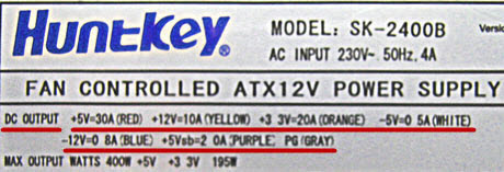
Notice what is underlined in red. "DC OUTPUT" (Direct Current Output - DC output value).
- +5V=30A (RED) - plus five IN, provides a current of 30 Amperes (red wire) We remember from the text above that we receive exactly +5V along the red wire?
- +12V=10A (YELLOW) - plus twelve IN we have a current of ten amperes (its wire is yellow)
- +3.3V=20A (ORANGE) - three point three line IN can withstand twenty amps of current (orange)
- -5V (WHITE) - minus five IN- similar to described above (white)
- -12V (BLUE) - minus twelve IN(blue)
- +5Vsb (PURPLE) - plus five IN standby. We have already talked about it above (it is purple).
- PG (GRAY) - Power Good signal (gray).
On a note: if, for example, the standby voltage according to measurements is not five volts, but, say, four, then it is very likely that we are dealing with a problematic voltage stabilizer (zener diode), which should be replaced with a similar one.
And the last entry from the list above tells us that the maximum output power of the product in watts is 400W, and only the 3 and 5V channels can provide a total of 195 watts.
Note: « "Power Good"- “nutrition is normal.” A voltage of 3 to 6 Volts (nominal 5V) is generated after the necessary internal checks through 100 - 500 ms(milliseconds, it turns out - from 0.1 to 0.5 seconds) after switching on. After this, the clock generator chip generates an initial setting signal. If it is missing, then another signal appears on the motherboard - a CPU hardware reset, preventing the computer from working with abnormal or unstable power.
If the output voltage does not correspond to the nominal voltage (for example, when it decreases in the mains), the “Power Good” signal disappears and the processor automatically restarts. When all required current values “P.G.” are restored is formed anew and the computer starts working as if it had just been turned on. Thanks to the quick turn off of the “Power Good” signal, the PC “does not notice” problems in the power system, since it stops operation before errors and other problems associated with its instability may appear.
In a properly designed unit, the issuance of the “Power Good” command is delayed until the power supply in all circuits is stabilized. In cheap power supplies, this delay is insufficient and the processor starts working too early, which, in itself, can even lead to corruption of the contents of the CMOS memory.
Now, armed with the necessary theoretical knowledge, we understand how to properly check a computer’s power supply using a multitester. We set the measurement limit on the DC scale to 20 Volts and begin checking the power supply.

We apply the black “probe” of the tester to the black “ground” wire, and start “poking” with the red one into all the remaining ones :)
Notes e: don’t worry, even if you start “feeling” for something wrong, you won’t burn anything - you’ll just get incorrect measurement results.
So, what do we see on the multimeter screen when checking the power supply?

On the +12V line the voltage is 11.37V. Remember, the Chinese tester showed us 11.3 (in principle, a similar value). But it still does not reach the minimum permissible of 11.40V.
Also pay attention to two useful buttons on the tester: “Hold” - holding measurement readings on the display and “Back Light” - backlighting the screen (when working in poorly lit rooms).

We see the same (not inspiring) 11.37V.
Now (for completeness) we need to check the power supply for other ratings. Let's test, for example, five Volts on the same Molex.

The black “probe” is to “ground”, and the red one is to the red five-volt pin. Here is the result on the multimeter:

As we can see, the indicators are normal. Similarly, we measure all other wires and compare each result with the nominal value from.
Thus, checking the power supply showed that the device has a greatly underestimated (relative to the nominal) voltage of +12V. Let's, for clarity, once again measure the same line (yellow color on the additional 4-pin connector) on a fully operational device.

We see - 11.92V (remember that the minimum permissible value here is 11.40V). This means we are well within the tolerance.
But checking the computer's power supply is only half the battle. After this, it also needs to be repaired, and we discussed this point in one of the previous articles, which was called.
I hope that now you yourself, if necessary, will be able to check the computer’s power supply, you will know exactly what voltages should be present at its terminals and act in accordance with this.
A thick bundle of wires of different colors comes out of the computer power supply and at first glance, it seems that it is impossible to figure out the pinout of the connectors.
But if you know the rules for color marking the wires coming out of the power supply, then it will become clear what the color of each wire means, what voltage is present on it and to which computer components the wires are connected.
Color pinout of computer power supply connectors
Modern computers use ATX power supplies, and a 20 or 24 pin connector is used to supply voltage to the motherboard. The 20-pin power connector was used during the transition from the AT standard to the ATX. With the advent of the PCI-Express bus on motherboards, 24-pin connectors began to be installed on power supplies.
The 20-pin connector differs from the 24-pin connector in the absence of contacts numbered 11, 12, 23 and 24. These contacts in the 24-pin connector are supplied with the duplicated voltage already present on the other contacts.

Pin 20 (white wire) previously served to supply −5 V in power supplies for ATX computers versions prior to 1.2. Currently, this voltage is not required for the operation of the motherboard, so in modern power supplies it is not generated and pin 20 is usually free.
Sometimes power supplies are equipped with a universal connector for connecting to the motherboard. The connector consists of two. One is a twenty-pin connector, and the second is a four-pin connector (with pin numbers 11, 12, 23 and 24), which can be attached to a twenty-pin connector and it becomes a 24-pin connector.

So if you are replacing a motherboard that requires a 24-pin connector instead of a 20-pin connector, you should pay attention; it’s quite possible that an old power supply will work if its set of connectors has a universal 20+4-pin connector.
In modern ATX power supplies, there are also auxiliary 4, 6 and 8 pin connectors to supply +12 V voltage. They serve to supply additional supply voltage to the processor and video card.

As you can see in the photo, the +12 V supply conductor is yellow with a black stripe.

A Serial ATA connector is currently used to power hard drives and SSDs. Voltages and contact numbers are shown in the photo.
Outdated power supply connectors
This 4-pin connector was previously installed in the power supply to power a floppy drive designed for reading and writing from 3.5-inch floppy disks. Currently found only in older computer models.

Floppy disk drives are not installed in modern computers, as they are obsolete.

The four-pin connector in the photo is the longest used, but is already obsolete. It served to supply +5 and +12 V supply voltage to removable devices, hard drives, and disk drives. Currently, a Serial ATA connector is installed in the power supply instead.
The system units of the first personal computers were equipped with AT-type power supplies. One connector consisting of two halves was suitable for the motherboard. It had to be inserted in such a way that the black wires were next to each other. The supply voltage to these power supplies was supplied through a switch that was installed on the front panel of the system unit. However, according to the PG pin, it was possible to turn the Power Supply on and off using a signal from the motherboard.

Currently, AT power supplies are almost out of service, but they can be successfully used to power any other devices, for example, to power a laptop from the network, in case of failure of its standard power supply, to power a 12 V soldering iron, or low-voltage light bulbs , LED strips and much more. The main thing is not to forget that the AT power supply, like any switching power supply, is not allowed to be connected to the network without an external load.
Color marking reference table,
voltage values and ripple range at power supply connectors
Wires of the same color coming out of the computer's power supply are soldered internally to one track of the printed circuit board, that is, connected in parallel. Therefore, the voltage on all wires of the same color is the same value.
| Table of color marking of wires, output voltages and ripple range of ATX power supply | |||||||
|---|---|---|---|---|---|---|---|
| Output voltage, V | +3,3 | +5,0 | +12,0 | -12,0 | +5.0 SB | +5.0 PG | GND |
| Wire color coding | orange | red | yellow | blue | violet | grey | black |
| Permissible deviation, % | ±5 | ±5 | ±5 | ±10 | ±5 | – | – |
| Permissible minimum voltage | +3,14 | +4,75 | +11,40 | -10,80 | +4,75 | +3,00 | – |
| Permissible maximum voltage | +3,46 | +5,25 | +12,60 | -13,20 | +5,25 | +6,00 | – |
| Ripple range no more than, mV | 50 | 50 | 120 | 120 | 120 | 120 | – |
Voltage +5 V SB (Stand-by) – (purple wire) is generated by an independent low-power power supply built into the power supply unit, based on one field-effect transistor and a transformer. This voltage ensures the computer operates in standby mode and serves only to start the power supply. When the computer is running, the presence or absence of +5 V SB voltage does not matter. Thanks to +5 V SB, the computer can be started by pressing the “Start” button on the system unit or remotely, for example, from an uninterruptible power supply unit in the event of a prolonged absence of 220 V supply voltage.
Voltage +5 V PG (Power Good) - appears on the gray wire of the power supply unit after 0.1-0.5 seconds if it is in good condition after self-testing and serves as an enabling signal for the operation of the motherboard.
When measuring voltages, the “negative” end of the probe is connected to the black wire (common), and the “positive” end is connected to the contacts in the connector. You can measure output voltages directly while the computer is running.
A voltage of minus 12 V (blue wire) is only needed to power the RS-232 interface, which is not installed in modern computers. Therefore, in power supplies of the latest models this voltage may not be present.
Installation in computer power supply
additional connector for video card
Sometimes there are seemingly hopeless situations. For example, you bought a modern video card and decided to install it in your computer. There is the necessary slot on the motherboard for installing a video card, but there is no suitable connector on the wires for additional power supply to the video card coming from the power supply. You can buy an adapter, replace the entire power supply, or you can independently install an additional connector on the power supply to power the video card. This is a simple task, the main thing is to have a suitable connector, it can be taken from a faulty power supply.

First you need to prepare the wires coming from the connectors for the offset connection, as shown in the photo. An additional connector for powering the video card can be connected to the wires going, for example, from the power supply to drive A. You can also connect to any other wires of the desired color, but in such a way that there is enough length to connect the video card, and preferably nothing to them was no longer connected. The black wires (common) of the additional connector for powering the video card are connected to the black wire, and the yellow wires (+12 V), respectively, to the yellow wire.
The wires coming from the additional connector for powering the video card are tightly wrapped with at least three turns around the wire to which they are connected. If possible, it is better to solder the connections with a soldering iron. But even without soldering, in this case the contact will be quite reliable.

The work of installing an additional connector for powering the video card is completed by isolating the connection point, several turns, and you can connect the video card to the power supply. Due to the fact that the twisting points are located at a distance from each other, there is no need to isolate each twist separately. It is enough to cover only the area where the wires are exposed with insulation.
Refinement of the power supply connector
to connect the motherboard
When the motherboard fails or a computer is modernized (upgraded) and involves replacing the motherboard, I have repeatedly had to deal with the lack of a 24-pin power supply connector on the power supply.

The existing 20-pin connector fit well into the motherboard, but the computer could not work with this connection. A special adapter or replacement of the power supply was required, which was an expensive pleasure.

But you can save money if you do a little work yourself. The power supply, as a rule, has many unused connectors, among them there may be four, six or eight pins. The four-pin connector, as in the photo above, fits perfectly into the mating part of the connector on the motherboard, which was left unoccupied when installing the 20-pin connector.

Please note that both in the connector coming from the computer's power supply and in the mating part on the motherboard, each contact has its own key, which prevents incorrect connection. Some contact insulators have a shape with right angles, while others have cut corners. You need to orient the connector so that it fits. If you can’t find the position, then cut off the interfering corner.

Separately, both the 20-pin and 4-pin connectors fit well, but they don’t fit together and interfere with each other. But if you grind down the contacting sides of both connectors a little with a file or sandpaper, they will fit in well.

After adjusting the connector housings, you can begin connecting the wires of the 4-pin connector to the wires of the 20-pin connector. The colors of the wires of the additional 4-pin connector are different from the standard one, so you do not need to pay attention to them and connect them as shown in the photo.
Be extremely careful, mistakes are unacceptable, the motherboard will burn out! Near left, pin No. 23, black in the photo, connects to the red wire (+5 V). Near right No. 24, yellow in the photo, is connected to the black wire (GND). The far left, pin No. 11, black in the photo, connects to the yellow wire (+12 V). The far right, pin No. 12, yellow in the photo, is connected to the orange wire (+3.3 V).

All that remains is to cover the connection points with a few turns of insulating tape and the new connector will be ready for use.

In order not to think about how to correctly install the assembly connector into the motherboard connector, you should apply a mark using a marker.
Like on a computer's power supply
supply voltage is supplied from the mains
In order for constant voltages to appear on the colored wires of the power supply, supply voltage must be applied to its input. To do this, there is a three-pin connector on the wall where the cooler is usually installed. In the photo this connector is at the top right. It has three pins. The outer ones are supplied with supply voltage using a power cord, and the middle one is grounding, and when connected through the power cord, it is connected to the grounding contact of the electrical outlet. Below on some power supplies, for example this one, there is a power switch.

In older houses, the electrical wiring is made without a grounding loop; in this case, the grounding conductor of the computer remains unconnected. Experience in operating computers has shown that if the grounding conductor is not connected, this does not affect the operation of the computer as a whole.
The power cord for connecting the Power Supply to the mains is a three-core cable, at one end of which there is a three-pin connector for connecting directly to the Power Supply. At the second end of the cable there is a C6 plug with round pins with a diameter of 4.8 mm with a grounding contact in the form of metal strips on the sides of its body.

If you open the plastic sheath of the cable, you can see three colored wires. Yellow - green– is grounding, and along brown and blue (may be of a different color), a supply voltage of 220V is supplied.

About the cross-section of wires coming out of the computer's power supply
Although the currents that the power supply can supply to the load amount to tens of amperes, the cross-section of the output conductors, as a rule, is only 0.5 mm 2, which allows the transmission of current up to 3 A through one conductor. You can learn more about the load capacity of the wires learn from the article “On choosing a wire cross-section for electrical wiring.” However, all wires of the same color are soldered to one point on the printed circuit board, and if a block or module in a computer consumes more than 3 A of current, voltage is supplied through the connector along several wires connected in parallel. For example, voltage +3.3 V and +5 V is supplied to the motherboard via four wires. This ensures that up to 12 A of current is supplied to the motherboard.
The power supply is an important component of the system, and without it the computer simply cannot work. It provides the required electrical energy to all consumers inside the computer case, while converting the AC voltage coming from the outlet into DC. When choosing a power supply for a computer, you need to be guided by its power, based on the number of consumers that will be connected to it. If the power supply fails, the entire computer will not work. That is why, if the computer stops turning on, it is important to check the power supply for functionality, and there are several ways to do this.
We recommend reading:Signs of a faulty power supply
There is no specific symptom by which one could say that the power supply in the computer has failed. There are a number of signs that are typical for the behavior of a computer when the power supply fails. It can be stated that the power supply is not working properly (or there is another problem) with the following “behavior” of the computer:
- When you press the power button, nothing happens, that is, there is no light or sound indication and the coolers do not start rotating. Since the power supply is a component that supplies other elements with constant voltage, there is a high probability that it has failed or there are other problems with the transfer of power to the computer elements - breaks in the wires, unstable supply of alternating voltage from the network;
- The computer does not always turn on the first time. In such a situation, the power supply, poor connection of connectors or a malfunction of the power button may be to blame;
- The computer turns off spontaneously while loading the operating system. This may occur due to intermittent voltage transfer from the power supply to other computer components. Also, a similar problem may indicate overheating of the power supply and forced shutdown.
The power supply is a reliable element of a computer that rarely fails. If the power supply is broken, the reason for this is its poor manufacturing quality or the supply voltage through the network with constant fluctuations. In addition, the power supply may fail if the calculation is made incorrectly when selecting it for a specific computer configuration.
How to check the power supply
If your computer has one of the symptoms listed above, you should not immediately blame the power supply. A malfunction may also occur for other reasons. To make sure there are problems with the power supply component of the system, it is necessary to carry out diagnostic work. There are 3 methods for checking your computer's power supply yourself.
Step 1: Check the Power Supply Transmits Voltage
To ensure that the power supply turns on, you must perform the following test:

It should be noted that this test shows the functionality of the power supply to turn on. But even if, according to its results, the power supply cooler begins to rotate, this does not mean that the device is fully operational. Proceed to the next steps to check the power supply.
Step 2: How to Test the Power Supply with a Multimeter
If you are sure that the power supply receives voltage from the network and is working, you need to check whether it supplies the required constant voltage. For this:
- Connect any external resistance to the power supply - floppy drive, hard drive, coolers;
- Next, take a multimeter set to measure voltage and connect the negative lead of the diagnostic tool to the black pin of the 20/24-pin power supply connector. When connected in this way, the black contact is considered grounding. Connect the positive probe of the multimeter one by one to the connector contacts to which wires of the following colors are suitable, and also compare the values with the ideal voltage:

During measurement, errors of ±5% are possible.
If the measured values differ from the ideal values, you can diagnose a faulty power supply and the need to replace it.
Step 3: How to Visually Check the Power Supply
If you don’t have a multimeter (or if you need additional diagnostics), you can visually check the power supply for a malfunction. For this:

When there are no problems with the capacitors, it is recommended to remove all dust from the power supply, lubricate the fan and reassemble the device, and then try to connect it.
Linear and switching power supplies
Let's start with the basics. The power supply in a computer performs three functions. First, alternating current from the household power supply must be converted to direct current. The second task of the power supply is to reduce the voltage of 110-230 V, which is excessive for computer electronics, to the standard values required by power converters of individual PC components - 12 V, 5 V and 3.3 V (as well as negative voltages, which we will talk about a little later) . Finally, the power supply plays the role of a voltage stabilizer.
There are two main types of power supplies that perform the above functions - linear and switching. The simplest linear power supply is based on a transformer, on which the alternating current voltage is reduced to the required value, and then the current is rectified by a diode bridge.
However, the power supply is also required to stabilize the output voltage, which is caused by both voltage instability in the household network and a voltage drop in response to an increase in current in the load.
To compensate for the voltage drop, in a linear power supply the transformer parameters are calculated to provide excess power. Then, at high current, the required voltage will be observed in the load. However, the increased voltage that will occur without any means of compensation at low current in the payload is also unacceptable. Excess voltage is eliminated by including a non-useful load in the circuit. In the simplest case, this is a resistor or transistor connected through a Zener diode. In a more advanced version, the transistor is controlled by a microcircuit with a comparator. Be that as it may, excess power is simply dissipated as heat, which negatively affects the efficiency of the device.
In the switching power supply circuit, one more variable appears, on which the output voltage depends, in addition to the two already existing: input voltage and load resistance. There is a switch in series with the load (which in the case we are interested in is a transistor), controlled by a microcontroller in pulse width modulation (PWM) mode. The higher the duration of the open states of the transistor in relation to their period (this parameter is called duty cycle, in Russian terminology the inverse value is used - duty cycle), the higher the output voltage. Due to the presence of a switch, a switching power supply is also called Switched-Mode Power Supply (SMPS).
No current flows through a closed transistor, and the resistance of an open transistor is ideally negligible. In reality, an open transistor has resistance and dissipates some of the power as heat. In addition, the transition between transistor states is not perfectly discrete. And yet, the efficiency of a pulsed current source can exceed 90%, while the efficiency of a linear power supply with a stabilizer reaches 50% at best.

Another advantage of switching power supplies is the radical reduction in the size and weight of the transformer compared to linear power supplies of the same power. It is known that the higher the frequency of alternating current in the primary winding of a transformer, the smaller the required core size and the number of winding turns. Therefore, the key transistor in the circuit is placed not after, but before the transformer and, in addition to voltage stabilization, is used to produce high-frequency alternating current (for computer power supplies this is from 30 to 100 kHz and higher, and as a rule - about 60 kHz). A transformer operating at a power supply frequency of 50-60 Hz would be tens of times more massive for the power required by a standard computer.
Linear power supplies today are used mainly in the case of low-power applications, where the relatively complex electronics required for a switching power supply constitute a more sensitive cost item compared to a transformer. These are, for example, 9 V power supplies, which are used for guitar effects pedals, and once for game consoles, etc. But chargers for smartphones are already entirely pulsed - here the costs are justified. Due to the significantly lower amplitude of voltage ripple at the output, linear power supplies are also used in those areas where this quality is in demand.
⇡ General diagram of an ATX power supply
A desktop computer's power supply is a switching power supply, the input of which is supplied with household voltage with parameters of 110/230 V, 50-60 Hz, and the output has a number of DC lines, the main ones of which are rated 12, 5 and 3.3 V In addition, the power supply provides a voltage of -12 V, and sometimes also a voltage of -5 V, required for the ISA bus. But the latter was at some point excluded from the ATX standard due to the end of support for the ISA itself.

In the simplified diagram of a standard switching power supply presented above, four main stages can be distinguished. In the same order, we consider the components of power supplies in the reviews, namely:
- EMI filter - electromagnetic interference (RFI filter);
- primary circuit - input rectifier (rectifier), key transistors (switcher), creating high-frequency alternating current on the primary winding of the transformer;
- main transformer;
- secondary circuit - current rectifiers from the secondary winding of the transformer (rectifiers), smoothing filters at the output (filtering).

⇡ EMF filter
The filter at the power supply input is used to suppress two types of electromagnetic interference: differential (differential-mode) - when the interference current flows in different directions in the power lines, and common-mode (common-mode) - when the current flows in one direction.
Differential noise is suppressed by capacitor CX (the large yellow film capacitor in the photo above) connected in parallel with the load. Sometimes a choke is additionally attached to each wire, which performs the same function (not on the diagram).
The common mode filter is formed by CY capacitors (blue drop-shaped ceramic capacitors in the photo), connecting the power lines to ground at a common point, etc. a common-mode choke (LF1 in the diagram), the current in the two windings of which flows in the same direction, which creates resistance for common-mode interference.

In cheap models, a minimum set of filter parts is installed; in more expensive ones, the described circuits form repeating (in whole or in part) links. In the past, it was not uncommon to see power supplies without any EMI filter at all. Now this is rather a curious exception, although if you buy a very cheap power supply, you can still run into such a surprise. As a result, not only and not so much the computer itself will suffer, but other equipment connected to the household network - switching power supplies are a powerful source of interference.
In the filter area of a good power supply you can find several parts that protect the device itself or its owner from damage. There is almost always a simple fuse for short circuit protection (F1 in the diagram). Note that when the fuse trips, the protected object is no longer the power supply. If a short circuit occurs, it means that the key transistors have already broken through, and it is important to at least prevent the electrical wiring from catching fire. If a fuse in the power supply suddenly burns out, then replacing it with a new one is most likely pointless.
Separate protection is provided against short-term surges using a varistor (MOV - Metal Oxide Varistor). But there are no means of protection against prolonged voltage increases in computer power supplies. This function is performed by external stabilizers with their own transformer inside.
The capacitor in the PFC circuit after the rectifier can retain a significant charge after being disconnected from power. To prevent a careless person who sticks his finger into the power connector from receiving an electric shock, a high-value discharge resistor (bleeder resistor) is installed between the wires. In a more sophisticated version - together with a control circuit that prevents charge from leaking when the device is operating.
By the way, the presence of a filter in the PC power supply (and the power supply of a monitor and almost any computer equipment also has one) means that buying a separate “surge filter” instead of a regular extension cord is, in general, pointless. Everything is the same inside him. The only condition in any case is normal three-pin wiring with grounding. Otherwise, the CY capacitors connected to ground simply will not be able to perform their function.
⇡ Input rectifier
After the filter, the alternating current is converted into direct current using a diode bridge - usually in the form of an assembly in a common housing. A separate radiator for cooling the bridge is highly welcome. A bridge assembled from four discrete diodes is an attribute of cheap power supplies. You can also ask what current the bridge is designed for to determine whether it matches the power of the power supply itself. Although, as a rule, there is a good margin for this parameter.
⇡ Active PFC block
In an AC circuit with a linear load (such as an incandescent light bulb or an electric stove), the current flow follows the same sine wave as the voltage. But this is not the case with devices that have an input rectifier, such as switching power supplies. The power supply passes current in short pulses, approximately coinciding in time with the peaks of the voltage sine wave (that is, the maximum instantaneous voltage) when the smoothing capacitor of the rectifier is recharged.

The distorted current signal is decomposed into several harmonic oscillations in the sum of a sinusoid of a given amplitude (the ideal signal that would occur with a linear load).
The power used to perform useful work (which, in fact, is heating the PC components) is indicated in the characteristics of the power supply and is called active. The remaining power generated by harmonic oscillations of the current is called reactive. It does not produce useful work, but heats the wires and creates a load on transformers and other power equipment.
The vector sum of reactive and active power is called apparent power. And the ratio of active power to total power is called power factor - not to be confused with efficiency!
A switching power supply initially has a rather low power factor - about 0.7. For a private consumer, reactive power is not a problem (fortunately, it is not taken into account by electricity meters), unless he uses a UPS. The uninterruptible power supply is responsible for the full power of the load. At the scale of an office or city network, excess reactive power created by switching power supplies already significantly reduces the quality of power supply and causes costs, so it is being actively combated.

In particular, the vast majority of computer power supplies are equipped with active power factor correction (Active PFC) circuits. A unit with an active PFC is easily identified by a single large capacitor and inductor installed after the rectifier. In essence, Active PFC is another pulse converter that maintains a constant charge on the capacitor with a voltage of about 400 V. In this case, current from the supply network is consumed in short pulses, the width of which is selected so that the signal is approximated by a sine wave - which is required to simulate a linear load . To synchronize the current consumption signal with the voltage sinusoid, the PFC controller has special logic.
The active PFC circuit contains one or two key transistors and a powerful diode, which are placed on the same heatsink with the key transistors of the main power supply converter. As a rule, the PWM controller of the main converter key and the Active PFC key are one chip (PWM/PFC Combo).
The power factor of switching power supplies with active PFC reaches 0.95 and higher. In addition, they have one additional advantage - they do not require a 110/230 V mains switch and a corresponding voltage doubler inside the power supply. Most PFC circuits handle voltages from 85 to 265 V. In addition, the sensitivity of the power supply to short-term voltage dips is reduced.
By the way, in addition to active PFC correction, there is also a passive one, which involves installing a high-inductance inductor in series with the load. Its efficiency is low, and you are unlikely to find this in a modern power supply.
⇡ Main converter
The general principle of operation for all pulse power supplies of an isolated topology (with a transformer) is the same: a key transistor (or transistors) creates alternating current on the primary winding of the transformer, and the PWM controller controls the duty cycle of their switching. Specific circuits, however, differ both in the number of key transistors and other elements, and in qualitative characteristics: efficiency, signal shape, noise, etc. But here too much depends on the specific implementation for this to be worth focusing on. For those interested, we provide a set of diagrams and a table that will allow you to identify them in specific devices based on the composition of the parts.
| Transistors | Diodes | Capacitors | Transformer primary legs | |
| Single-Transistor Forward | 1 | 1 | 1 | 4 |
| 2 | 2 | 0 | 2 | |
| 2 | 0 | 2 | 2 | |
| 4 | 0 | 0 | 2 | |
| 2 | 0 | 0 | 3 |
In addition to the listed topologies, in expensive power supplies there are resonant versions of Half Bridge, which are easily identified by an additional large inductor (or two) and a capacitor forming an oscillatory circuit.
|
Single-Transistor Forward |
|
|
|
|
|
|


⇡ Secondary circuit
The secondary circuit is everything that comes after the secondary winding of the transformer. In most modern power supplies, the transformer has two windings: 12 V is removed from one of them, and 5 V from the other. The current is first rectified using an assembly of two Schottky diodes - one or more per bus (on the highest loaded bus - 12 V - in powerful power supplies there are four assemblies). More efficient in terms of efficiency are synchronous rectifiers, which use field-effect transistors instead of diodes. But this is the prerogative of truly advanced and expensive power supplies that claim the 80 PLUS Platinum certificate.
The 3.3V rail is typically driven from the same winding as the 5V rail, only the voltage is stepped down using a saturable inductor (Mag Amp). A special winding on a transformer for a voltage of 3.3 V is an exotic option. Of the negative voltages in the current ATX standard, only -12 V remains, which is removed from the secondary winding under the 12 V bus through separate low-current diodes.
PWM control of the converter key changes the voltage on the primary winding of the transformer, and therefore on all secondary windings at once. At the same time, the computer's current consumption is by no means evenly distributed between the power supply buses. In modern hardware, the most loaded bus is 12-V.
To separately stabilize voltages on different buses, additional measures are required. The classic method involves using a group stabilization choke. Three main buses are passed through its windings, and as a result, if the current increases on one bus, the voltage drops on the others. Let's say the current on the 12 V bus has increased, and in order to prevent a voltage drop, the PWM controller has reduced the duty cycle of the key transistors. As a result, the voltage on the 5 V bus could go beyond the permissible limits, but was suppressed by the group stabilization choke.
The voltage on the 3.3 V bus is additionally regulated by another saturable inductor.
A more advanced version provides separate stabilization of the 5 and 12 V buses due to saturable chokes, but now this design has given way to DC-DC converters in expensive high-quality power supplies. In the latter case, the transformer has a single secondary winding with a voltage of 12 V, and the voltages of 5 V and 3.3 V are obtained thanks to DC-DC converters. This method is most favorable for voltage stability.
Output filter
The final stage on each bus is a filter that smoothes out voltage ripple caused by the key transistors. In addition, the pulsations of the input rectifier, whose frequency is equal to twice the frequency of the supply network, penetrate to one degree or another into the secondary circuit of the power supply.
The ripple filter includes a choke and large capacitors. High-quality power supplies are characterized by a capacitance of at least 2,000 uF, but manufacturers of cheap models have reserves for savings when they install capacitors, for example, of half the nominal value, which inevitably affects the ripple amplitude.
⇡ Standby power supply +5VSB
A description of the components of the power supply would be incomplete without mentioning the 5 V standby voltage source, which makes the PC sleep mode possible and ensures the operation of all devices that must be turned on at all times. The “duty room” is powered by a separate pulse converter with a low-power transformer. In some power supplies, there is also a third transformer, which is used in the feedback circuit to isolate the PWM controller from the primary circuit of the main converter. In other cases, this function is performed by optocouplers (an LED and a phototransistor in one package).

⇡ Methodology for testing power supplies
One of the main parameters of the power supply is voltage stability, which is reflected in the so-called. cross-load characteristic. KNH is a diagram in which the current or power on the 12 V bus is plotted on one axis, and the total current or power on the 3.3 and 5 V buses is plotted on the other. At the intersection points for different values of both variables, the voltage deviation from the nominal value is determined one tire or another. Accordingly, we publish two different KNHs - for the 12 V bus and for the 5/3.3 V bus.
The color of the dot indicates the percentage of deviation:
- green: ≤ 1%;
- light green: ≤ 2%;
- yellow: ≤ 3%;
- orange: ≤ 4%;
- red: ≤ 5%.
- white: > 5% (not allowed by ATX standard).
To obtain KNH, a custom-made power supply test bench is used, which creates a load by dissipating heat on powerful field-effect transistors.

Another equally important test is determining the ripple amplitude at the power supply output. The ATX standard allows ripple within 120 mV for a 12 V bus and 50 mV for a 5 V bus. A distinction is made between high-frequency ripple (at double the frequency of the main converter switch) and low-frequency (at double the frequency of the supply network).
We measure this parameter using a Hantek DSO-6022BE USB oscilloscope at the maximum load on the power supply specified by the specifications. In the oscillogram below, the green graph corresponds to the 12 V bus, the yellow graph corresponds to 5 V. It can be seen that the ripples are within normal limits, and even with a margin.
For comparison, we present a picture of ripples at the output of the power supply of an old computer. This block wasn't great to begin with, but it certainly hasn't improved over time. Judging by the magnitude of the low-frequency ripple (note that the voltage sweep division is increased to 50 mV to fit the oscillations on the screen), the smoothing capacitor at the input has already become unusable. High-frequency ripple on the 5 V bus is on the verge of permissible 50 mV.


The following test determines the efficiency of the unit at a load from 10 to 100% of rated power (by comparing the output power with the input power measured using a household wattmeter). For comparison, the graph shows the criteria for the various 80 PLUS categories. However, this does not cause much interest these days. The graph shows the results of the top-end Corsair PSU in comparison with the very cheap Antec, and the difference is not that great.

A more pressing issue for the user is the noise from the built-in fan. It is impossible to directly measure it close to the roaring power supply testing stand, so we measure the rotation speed of the impeller with a laser tachometer - also at power from 10 to 100%. The graph below shows that when the load on this power supply is low, the 135mm fan remains at low speed and is hardly audible at all. At maximum load the noise can already be discerned, but the level is still quite acceptable.
The power supply is the “heart” of power supply to computer components. It converts the incoming AC voltage into DC voltage of +3.3 V, +5 V, +12 V.
1. Computer power supply, its connectors and voltages
2. Power calculation
3. Main characteristics of power supplies
Computer power supply, its connectors and voltages
Computer components use the following voltages:
3.3V - Motherboard, memory modules, PCI, AGP, PCI-E cards, controllers
5B - Disk drives, drives, PCI, AGP, ISA
12V - Drives, AGP cards, PCI-E
As you can see, the same components can use different voltages.
Function PS_ON allows you to turn the power supply off and on programmatically. This function turns off the power supply when the operating system is completed.
Signal Power_Good. When you turn on the computer, the power supply performs a self-test. And if the output supply voltage is normal, it sends a signal to the motherboard to the processor power management chip. If it does not receive such a signal, the system will not start.
It happens that the power supply does not have enough connectors. You can get out of this situation by using various adapters and splitters:

Power calculation
The output powers for each line are usually written on the power supply sticker and are calculated using the formula:
Watts (W) = Volts (V) x Amps (A)
Thus, adding up all the powers for each line we get the total power of the power supply.

However, often the output power does not correspond to the declared one. It is better to take a slightly more powerful unit to compensate for the possible lack of power.
I think it’s better to give preference to proven brands, but it’s not a guarantee that the block will be of high quality. There is only one way to check it - open it. There must be massive radiators, high-capacity input capacitors, a high-quality transformer, all parts must be soldered

Main characteristics of power supplies
Power supplies cannot operate without load. When checking it, you need to connect something to it. Otherwise, it may burn out or, if there is protection, it will turn off.
You can start it by short-circuiting two wires on the main ATX connector, green and any black.

Characteristics:


