How to connect a pass-through switch with 4 lamps. Step-by-step diagrams for connecting a pass-through switch from two places. Schematic diagram of a pass-through switch
A practical walk-through switch, the connection diagram of which is quite accessible for independent installation, allows you to control the lighting system from two or more places.
However, when connecting such a device, you must remember that all switches of this type can only be used in conjunction with other devices of a similar purpose.
Pair-of-way switching devices or “pass-through” switches refer to devices that close a specific circuit in different positions.
 When two lamps are connected to them, in one of the positions the operation of the first light source is ensured, and in the other the operation of the second lighting device is ensured.
Such switches have three connectors for connection and, as a rule, are used in feed-through circuits if it is necessary to connect two independent switches for one consumer.
A valuable advantage of a pass-through switch is the ability to control the operation of any number of lamps from several points.
In this case, for example, the traditional, most common switches, simply interrupt the electrical circuit by opening it.
Pass-through single devices are equipped with three contacts, which makes them switchable. According to its operating principle, such a switching device is a system based on a pair of switches mounted in the most convenient places for operation. Thanks to this feature, the consumer can turn on the lighting from one place and then turn it off at a completely different point.

If the pass-through switch is equipped with several keys and belongs to the multi-key category, then the number of contacts and switching circuits increases many times, and control can be carried out for two or more groups of lighting devices.
It is important to remember that the basis of the operating principle of any pass-through type switches is the switching process based on reversing conductors. Inside the distribution box, such elements are combined using standard terminals. Each switching device must have a power supply conductor, and the second switch, in this case, is used to connect the wired element to the lighting.
The presence of a phase on two conductors requires the mandatory use of exclusively three-wire wire, and when installing a lighting system on three control points, it will be necessary to use four-wire wiring.
According to the control method, all currently produced switching devices belonging to the “pass-through” type are, as a rule, represented by easy-to-use, key-based devices.
Scope of use
Pass-through switches are in demand when arranging a lighting system in the following cases:
- long corridors in which one of the switches is mounted at the beginning of the room, and the other is installed at the end;
- multi-storey residential buildings or public buildings;
- interfloor staircase space, allowing the installation of switching devices on different floors;
- bedrooms, where switches are installed next to the doorway, as well as above or next to the sleeping area.

Pass-through switches are especially in demand in street lighting, as well as for providing comfortable lighting in basements, terraces, verandas or gazebos.
Kinds
The choice of pass-through switching devices is not very extensive, however, when selecting the optimal option, it is necessary to take into account the specific features of such switching devices.
The basic classification of pass-through switches does not differ significantly from the characteristics of traditional type switches, therefore such devices can be:
- single-key devices with one input and two outputs;
- two-key devices with two inputs and four outputs;
- three-key devices, with three inputs and six outputs.
Depending on the type of control, pass-through switching devices can be different, but the most common are keypad, touchscreen and remote-controlled models. It should be noted that when choosing, you need to take into account the number of keys, which must fully correspond to the number of groups of lamps that can be turned on simultaneously.
It is important to remember that the use of single-key or two-key cross-type switches for two inputs and the same number of outputs is advisable when controlling lighting from three or more points.
How to connect a pass-through switch: connection diagram
Automatic switching on and off of lighting fixtures can easily be organized using special timers or sensors that can respond to movement.
However, such electronic devices are characterized by high cost, difficulty in connecting independently and insufficient durability, so it is much easier and more practical to install a pass-through switch yourself.

Connection diagram for single-key pass-through switch
At the stage of preparation for installation, it is necessary not only to calculate the number of consumers and the amount of consumables, but also to prepare all the tools necessary for installation, presented:
- Phillips screwdriver;
- flat-head screwdriver;
- mounting knife;
- side cutters;
- building level and tape measure;
- a probe screwdriver with a built-in phase indicator.
The set of working tools and basic consumables may vary depending on the chosen method for laying cable ducts, as well as depending on the characteristics of construction and finishing materials in the room where the lighting system is supposed to be installed.

Connection diagram for pass-through switch
In wooden households, in order to prevent emergency and fire hazards, cables must be installed inside a copper or steel pipe.
It is also possible to carry out open installation of electrical wiring.
It should be noted that the use of corrugated polymer and metal tubes for electrical wires is prohibited, in accordance with the standards established by PTEEP and PUE, and cable laying in non-combustible structures is carried out by cutting special channels.
Lighting control
Depending on the type of lighting system you prefer, wiring can be connected in different ways. Despite the fact that the design features of all standard pass-through switches are the same, there are several differences in the connection diagram of the system with control of two and three places.
Before you begin self-installation, you must turn off the electrical power supply, which is dictated by safety regulations.
 Control from 2 places
This method of organizing the control of lighting devices is most often used when it is necessary to control the process of turning on/off light sources not only from the room itself, but also from adjacent rooms.
In this case, as a rule, preference is given to installing switching devices to control a couple of consumer groups:
- thorough removal of decorative coatings in the wiring area;
- marking the proposed wiring line;
- scoring according to the markings made, starting from the shield, taking into account the free distance to the upper edge of the cable channel with dimensions of ½ the diameter of the laid wires;
- checking the horizontality of the completed lines;
- laying electrical cable. It is quite possible to fix laid electrical wires with special fasteners without damaging the protective sheath;
- installation of switches and distribution boxes;
- connecting laid electrical conductors to terminals in accordance with color markings.

Lighting control scheme from two places
The assembled wiring is inserted into special mounting boxes, after which they are securely and durablely fixed with built-in retractable mechanisms with pointed elements.
Only after testing has been carried out and the operability of the entire lighting system has been confirmed, cable channels are cemented, wall surfaces are finished and frames are installed.
Control from 3 seats
Independent installation of control from three places is a more complex system that can cause some difficulties for untrained installers. The most common electrical circuit is based on one crossover and a pair of pass-through switches.
Work technology:
- preliminary preparation of grooves for laying electrical cables using a hammer drill;
- laying electrical cables with an optimal cross-section of 2.5 mm 2 or more;
- connecting wires to the electrical panel;
- choose the optimal height for mounting the switch that is comfortable for operating the switching device;
- Drill a hole in accordance with a pre-made mark, which is one and a half times larger in width and depth than the diameter of the device being installed;
- electrical wiring is connected to the switching device from below, so the groove must be made 50-100 cm lower than the switch installation point;
- laying electrical wires in prepared grooves with fixing the wiring elements using small special nails;
- insertion of electrical wires fixed in the channels into the installation box;
- cutting the wires inside the wiring box to a length of 10-11 cm using side cutters;
- removing approximately 10-15 cm of the insulating layer from the wires;
- installation of a pass-through switching device (switch) with connection to the terminals, according to their markings;
- installation of a cross-switching device with four electrical cables of the corresponding color marking;
- connecting the first pair of electrical cables from the pass-through switch to the upper terminals, and the remaining two wires are fixed to the lower terminals;
- connecting the last switching device using wires coming from the communication crossover device.

Connection from three places
At the final stage, it is necessary to carefully insert the device mechanisms inside all the completed mounting boxes, bending the cables to their base.

Then the devices are fixed using special fasteners inside the mounting box or “claws” on the clamps. Next, the frame is applied, and then the keys of the switching device are mounted.
Wiring when controlling the lamp from three places
The completion of self-installation of a switch to control the lighting system from three different points is the connection of lighting fixtures with electrical cables coming from the junction box, checking the functionality of the circuit and subsequent decorative finishing.
When choosing such a device, you need to take into account the design features, as well as their functional purpose.
 In order to implement various schemes for controlling electrical energy consumers, double or triple type switches are used, as well as standard crossover devices.
If there are long corridors in a house or apartment, then a pass-through switch will significantly simplify the lighting system. – procedure for installation work.
The rules for measuring current with a multimeter are outlined.
Most often, internal installation is used, which is reliable, aesthetically pleasing and guaranteed safety.
In any case, the main condition for proper installation and safe operation is strict adherence to the entire lighting connection diagram.
Video on the topic
Reading time ≈ 3 minutes In the modern world, we increasingly strive to make our routine life easier in all available and not so accessible ways. Even such a minor procedure as connecting a pass-through switch in the house. In fact, it is not nearly as complicated as it might seem at first glance and does not require special efforts. First of all, it is worth saying what is a pass-through switch
, and why, in fact, install it.
Such easy-to-use examples are most relevant in private homes or country houses, as they allow you to connect one light source to two switches at once. That is, it becomes possible to turn on and off a lamp (or even several at once) from two points. You can also find names such as backup and changeover, which are applied to the same type of switch.

Connection diagram for pass-through switch
Frankly speaking, the wiring diagram for a pass-through switch is understandable to almost everyone. It involves the use of two pass-through switches of exclusively single type. Each of these ordinary switches has three contacts, including 2 outputs and 1 input. The neutral wire from the main power source goes to the lamp directly through the distribution box. A phase wire already passes into it, then it goes to the switch contact number 1. Through the distribution box, the two output contacts of the first switch are gradually connected to the two input contacts of switch 2. Then from the common contact of a separate second pass-through switch, the contact goes through the same distribution box directly to lamp.

Connecting a two-key pass-through switch is no more complicated. It makes it possible to control different groups of individual light bulbs or luminaires. The main difference between the scheme is, first of all, that to implement the plan, two double switches are required, and not single ones, as shown in the previous diagram. They are also called two-key. They already have 6 contacts, including 4 outputs and 2 inputs. Connecting a double pass-through switch follows a similar principle.
Connection diagram for three pass-through switches:

The connection diagram for three pass-through switches is intended to directly control one light source from three separate places at once. This circuit includes a coupled double type switch. It is actually different from both doubles and singles. First of all, the fact that it has four contacts, two inputs and outputs, respectively. Pressing this double switch makes it possible to switch two independent contacts at once.
For a more detailed understanding of the connection process, of course, a clear example is needed. Therefore, you can see the features of connecting pass-through switches in video and photos directly in our article. This will definitely make the task easier.
Switching light sources according to the principle “approach, turn on, pass, turn off” is one of the options for the efficient use of electrical energy. The functionality of such a control system is provided by the same traditional devices - switches, but structurally somewhat modernized.
Switching modernization allows you to connect a pass-through switch from two or three places in order to control the light source from each individual point. Agree, this solution is especially convenient for long rooms, for example, a corridor.
We suggest you understand the principles of connecting a pass-through switch to two and three control points. The article provides working diagrams for organizing light groups, and also describes the features of the implementation of switching projects.
The logic of saving energy spent on lighting devices or others is explained by simple user actions.
If a lighting device is needed, electricity is supplied to it by simply closing the switch contact. Otherwise, the opposite action is performed.
Light source switch - interpreted in electrical slang - a pass-through switch. Provides a fundamentally new approach in terms of operation of electrical sections of networks intended for the installation of lighting devices (+)
However, let’s assume that the premises (residential or other purposes) are passable. Then the user will turn on the lights at the entrance, but when leaving the room through another door, he will no longer be able to de-energize the circuit. There is irrational use of electricity.
But the situation is easy to improve. And the option of connecting from two places in the room for a pass-through mode scheme will help to do this.

Long corridors of premises for different purposes are potential objects for the installation of control systems for light sources from different places. It is during the operation of such premises that the pressing issue of energy saving is raised.
For example, there is a room with a functional purpose - a corridor. It is required to control the general group of lamps for this room from two points - at the first (passage) door and at the second (passage) door.
Switching light from two places
The lighting of the project corridor consists of two light groups, so in this case it is logical to use two two-key switches for control.
Accordingly, in addition to them you will need:
- two socket boxes;
- one ;
- three-core cable.
The meterage of electrical conductors should be calculated after drawing up the diagram and layout of the wiring. It is recommended to purchase a cable with a small reserve.
The control circuit for two light groups through two-key pass-through switches looks something like this:
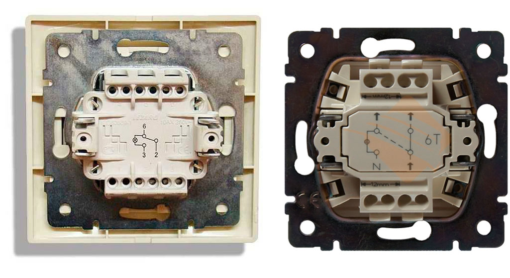
This is the same switch, but in terms of circuit design it is made with five contact terminals, two of which are short-circuited with a jumper. The switching group of such a switch contains four contact pads.

A widely used circuit design for residential buildings: N, L – household network; RK – distribution box; L1 – light group; PV1, PV2 – pass-through switches; PRK – cross commutator (+)
The line cross-switching device is an additional element of the circuit, which also involves the installation of two pass-through switches.
Simple single-key instruments are used.
The operating principle of the three-seater scheme is as follows:
- A phase is connected to the “common” terminal PV1.
- The 1st and 2nd contacts of the crossover switch are connected from the changeover contact terminals.
- From the 3rd and 4th terminals of the crossover switch, connection to the 1st and 2nd terminals of the PV2 changeover contacts.
- The common terminal “common” PV2 is connected to one terminal of the light group.
- The second terminal of the light group is connected to the electrical zero.
Such solutions involving simple single-key devices are recommended for use in rooms where the number of inputs/outputs is equal to the number of control places.

Implementation of the circuit design according to Fig. 6 in a “natural” form. This is roughly what a completed installation looks like indoors, where a control system from three places is needed
For example, creating a similar circuit for the conditions of passing a long corridor, with 1 entrance and 1 exit, with switching in the central zone, is clearly impractical. Obviously, it makes no sense to turn off the lights when a person has only passed the first half of the corridor. Meanwhile, you can find similar recommendations from “professional” electricians on the Internet.
Schemes with control from more than three places
The number of control places is, in principle, unlimited. Another question is how complex such decisions are. The more devices are involved in the implementation of the control system, the more complex the construction scheme becomes.
The number of switched lines and contact terminals is increasing. Accordingly, costs for components and installation increase. However, projects with 4-5 control points are used quite actively. For example, this project:
It uses a pair of single-key simple pass-through switches and a pair of switches with a reversible switching function. The diagram shows only one light group. Meanwhile, it is possible to connect additional light groups.
Additional light groups
Additional light sources (light groups) can be connected via free terminals and act as light sources for intermediate transition zones. That is, in the same long corridors it becomes possible to use the circuit for a larger number of control positions.

Five-point control circuit for the light switching system: L1 – light group; N, L – network; On 1, On 2 – pass-through switches; On 3, On 4, On 5 – reversible switches (+)
In this case, light groups should be divided into action zones - entrance, intermediate, exit. With this solution, it is already possible to walk through a long corridor halfway, turn off the lights on the completed half and turn on the lights on the remaining half.
Multi-element schemes, of course, are of little use for the private residential sector, since projects of this kind rarely have long corridors or large rooms with several doors. But for the commercial sphere or production environment, solutions of this kind are in demand.
Principles of control system design
In general, there are no installation features for installing pass-through switches. All installation work is carried out in a standard manner, in accordance with the rules for installing conventional switching devices.

Classic installation detail for wiring inside walls. The socket box is installed (tightly walled up). An electrical cable is routed inside the socket box. A control device is connected (two-key)
If the budget allows, it is advisable to equip each individual device with a distribution box. Then you need to purchase small boxes according to the number of mounted switches. But the option with one RC is also not excluded.
The selection factors here are directly related to specific installation conditions. Typically, switches are installed “flush” with the wall surface - internal wiring diagram.
Meanwhile, the implementation of projects for private (country) properties often involves the installation of “overhead” (surface) installation schemes, despite the fact that this approach is considered obsolete.
For the first case, socket boxes will be required for installation. For the second - overhead plates. These accessories are necessary to securely mount switches in wall panel niches or directly on walls.

The cable is connected strictly according to the diagram indicated on the back of the device. The circuit layout of a single-key switch is simple. However, mismatch of conductors with incorrect wiring can result in failure of the device.
The electrical conductor, as a rule, is three-core cables, where two cores are needed to power the system, and the third is used to form a protective grounding loop.
Household lamps can be used without an “earth” if the body is non-metallic. Industrial lamps must have a grounding bus.
Of course, regardless of its purpose, domestic or industrial, the installed network is always connected through additional protection -. This device must be calculated based on power and cut-off current in relation to the built-through light control system.
Analysis of possible errors:
The appearance and implementation of devices of this kind in electrical networks may not be so significant, but still affected the ease of use. Moreover, solutions based on pass-through switches actually lead to energy savings.
Meanwhile, the improvement of devices does not stop. New developments appear periodically, for example, similar to touch switches.
Do you have anything to add or have questions about connecting the pass-through switch? You can leave comments on the publication, participate in discussions and share your own experience in arranging an electrical network. The contact form is located in the lower block.
Controlling lighting fixtures from different locations is a very convenient option for long corridors, staircases or galleries. Indeed, it’s not very pleasant to come home, turn on the light downstairs, go up to the room, and then go down again to turn off the lighting. In this case, the return path will have to be overcome in the dark. It is much more convenient to turn it on at the beginning of the stairs, and turn it off at the end, and the same in the opposite direction. It is for such situations that pass-through switches (PB) are used, which allow you to control lamps from several points independently of each other. In this article we will tell you how to connect a pass-through switch and present step-by-step diagrams.
Connecting pass-through switches: step-by-step instructions
The devices in question do not have a neutral position to ensure a break in the electrical circuit. They are capable of directing the flow of electricity in one direction or another by closing different contacts. Therefore, the principle of their operation is based on their performance as limit switches, changing the state of the electrical circuit at different parts of its length. Moreover, they do not duplicate each other, but work autonomously, although they are elements of the same circuit. In addition to ease of use, this control method saves energy. Read also the article: → "".
The use of pass-through switches makes available equipment for lighting networks consisting of one or more lines and controlled from two or more points. Each connection option will be considered schematically and described step by step, which will allow the user to evaluate the advantages of this connection system and make the switching independently.
Control scheme from two places
This is the simplest method, which involves installing two single-key devices on different sections of the route (corridor, stairs). All connections are made only on the phase conductor and its branching between two PVs. The neutral wire is sent directly to the consumer; it does not take part in the connection process. The switching method is indicated in the diagram:
 A simple diagram for connecting one lighting line using two PVs
 The step-by-step wiring procedure can be described as follows:
- Each pass-through switch has terminals 2.3, between which the flowing current is distributed. The terminals of both devices are connected to each other
- The central input of the first PV is connected to the 220 V phase wire
- The second PV is switched with the consumer.
Thus, each of the devices can close or open a circuit depending on the position of the contacts relative to each other.
Practical advice: wiring can be done in two distribution boxes located near each of the switches, or in one box mounted in the middle of the line. The second method may seem more attractive, but in reality it will require a longer length of wires, as well as a larger number of twists in one box.
 General view of the parts of the electrical circuit of the lighting network in assembled condition
 Control circuit for two lighting lines
With this arrangement, two-key products are used, in which each of the keys performs switching operations on one of the lighting lines. Read also the article: → "".
The connection process can be presented in step-by-step instructions:
- The phase conductor is connected to the input terminal of the first pass-through switch, where it is connected to the second input using a jumper
- The terminals of the outputs of both supply voltages are connected to each other in pairs and correspondence to the device keys
- The input terminals of the second switch are mounted each with its own wire of the lighting line (lighting device).
The neutral conductor is common to both lines. Thus, each key of the device controls its own electrical circuit in one of the sections, turning the light on or off.
 Connecting two lighting lines using switches with two keys
 Three-seat control scheme
The uniqueness of this system lies in the ability to control lighting through three circuits. It includes an additional device, which, according to the principle of operation, is pass-through, but unlike the previously discussed models, it has two inputs, two outputs and a paired moving contact operating between three fixed ones. This element is called a cross switch. It is installed in the third section, from which the light is turned on and off.
To draw up the circuit, two single-key switches, one cross switch and two distribution boxes are used. The step-by-step connection process will look like this:
- The 220 V network phase conductor is connected to the input of the first PV
- The second PV input is connected to the lighting line
- The outputs of both pass-through switches are connected to the corresponding outputs of the crossover device.
The wires are connected in junction boxes, of which there can be two (as shown in the diagram) or three.

Connection diagram for pass-through devices with socket
To create a network of lighting devices with the ability to turn on and off from several points, you can use an L-conductor from the old lighting line as a phase, connecting the input of the first PV to it and then wiring according to one of the above methods.
 Appearance of a block combining a socket and a power source in one device
 In the case of installing a new circuit, the phase wire can be removed from the nearest outlet or its conductor can be found in the junction box by testing.
Also, one of the simple options is to install a switch-socket unit, which always looks solid and is very practical in everyday life.
An ordinary wire with a metal core corresponding to the material of the electrical wiring and not exceeding its cross-section should serve as a jumper between the socket phase and the switch. The wiring between devices and distribution boxes is carried out either hidden, in a groove under a layer of putty, or by laying it in cable channels.
Selection of pass-through switches
The choice of devices for controlling lighting fixtures depends on the connection diagram, the number of points and the personal preferences of the user.

In addition, products can be divided according to the method of installation into mortise and external (overhead) models. Devices are also distinguished:
- mechanical, operating by pressing;
- sensory, triggered by a light touch;
- remote, operating from an infrared remote control.
Remote models are most often used in large living rooms or spacious offices, where it can be useful to control lighting lines from anywhere in the room (leave one of the lamps or turn on all of them at once). Read also the article: → "".
Manufacturers of walk-through switches
Online stores vying with each other to offer electrical goods from different manufacturers, among which you can see products from well-known brands and products from unfamiliar companies. Users are offered a comparative analysis of some brands of domestic and foreign manufacturers, the purpose of which is not to give ratings or advertise one of the companies.
| No. | Brand name | A country | Product type | price, rub. |
| 1. | Legrand Valena | France | PV single-key | 650 |
| 2. | TDM Electric | Russia | // | 150 |
| 3. | Schneider Electric | France | // | 300 |
| 4. | Volsten | Russia | // | 160 |
| 5. | Makel | Türkiye | // | 200 |
The information provided is the average market value of the models of these companies and cannot reliably reflect the overall picture of the price values of all goods. The cost of a product depends on its functionality, materials used and brand recognition. For example, Legrand Valena and Schneider Electric are well-known brands all over the world. Their products are of high quality, which is confirmed by the warranty periods provided by the manufacturers.
Mistakes made when installing pass-through switches
Among the mistakes made by novice electricians, the most common ones should be noted, which can affect the quality of work on installing and connecting devices to control lighting fixtures from several places.
- Trying to make all connections in one junction box. This option is possible when switching a simple single-line diagram with two devices. For more complex connections, the connection sections should be separated into two or even three boxes to avoid a large number of twists in one place. Otherwise, it may result in a short circuit due to insufficient insulation and difficulty in subsequent maintenance or repair.
 A large number of twists in one place can lead to a short circuit and complicate repairs
 - The use of wires with different materials of current-carrying cores. Such a connection is unacceptable, because during operation oxidation will certainly occur and contact will be lost.
- Installation of splices in the cable channel gutter or under a layer of plaster for hidden wiring. This can lead to electric leakage due to insulation failure as a result of the wall getting wet or condensation accumulating in the box. As a result, current may break through to the wall or permanently trigger protective equipment (RCD).
- Incorrect design of connections when connecting wires. The twist must be tightly tied and have a length of at least 25 mm. Under this condition, the contact will be reliable and durable. And the most correct solution would be to use terminal blocks.
Practical advice: When insulating a joint, it is better to additionally put a protective cap on top of the insulation. This will provide better short circuit protection.
Current questions on the topic
Question No. 1. Is it possible to install pass-through switches without inserting wires into distribution boxes?
This is quite real. Boxes are needed to supply a phase to the first device and direct the wire to the lighting fixture from the last. The rest of the switching between devices can be carried out in single pieces of wires from terminal to terminal. If the wiring is hidden, the overall appearance of the room will not be affected. If the wires are placed in a box or corrugation, then an unsightly cable will stretch along the entire wall.
Question No. 2. Why, instead of a complex system of installing pass-through switches, not use motion sensors that will turn on the lights in the corridor when there is movement and turn them off when there is no movement?
This is indeed possible, but there are some circumstances that argue against such a solution. The first reason is high cost; motion sensors are much more expensive than switches. The second is an inconvenience; if for some reason the user stops, the light will go out. The reasons for stopping may vary. It's good if it happens in a narrow passage. What if it's on the stairs? Now imagine a huge office where people need to constantly move in order to keep the lights on, instead of concentrating on work. You can, of course, install a backup switch, but then the whole meaning of the plan is lost.
Question No. 3. If there are switches that work with a remote control, then why not install such a device at one end of the corridor, and put a remote control at the other end so that you can turn it on or off if necessary?
This would be too simple a solution if the remote control did not require power. As always, the batteries will run out at the most inopportune moment. In addition, the range of any emitted signal is limited, which means that the remote control is not suitable for every situation. Not all rooms, and especially stairs, have a rectilinear shape. The remote control is ineffective in these cases.
In conclusion, it can be noted that the use of pass-through devices, although it can cause some confusion associated with their installation and connection, will in the future only bring comfort and ease of use. Therefore, the number of users who have decided in favor of positive changes is constantly increasing.
Prices for housing and communal services increase every year, which makes us think about saving, including electricity. Moreover, this applies to places that people had never even thought about before. For example, lighting of stairs and landings in multi-storey buildings. In the recent past, when electricity prices were meager, staircases were illuminated 24 hours a day. This problem is also relevant in private houses that have more than one floor connected by a staircase. To save money, you have to turn off the lights, but to do this you need to either go down the stairs again or go up them. This is extremely inconvenient, so sometimes they simply don’t turn it off and it burns until the morning, when it doesn’t get light.
For the convenience of lighting in such areas, so-called “pass-through” switches were developed. They are also called “duplicate” or “change-over”. They can be distinguished from classic switches by the presence of a larger number of contacts. Therefore, in order to connect them, you need to know the circuit, and even more so, be able to understand the principle of their operation. Naturally, this is not entirely simple, but it is absolutely possible.
On the key of the pass-through switch there are two arrows (not large), directed up and down.
 This type is a pass-through single-key switch. There may be double arrows on the key.
 The connection diagram is not much more complicated than the connection diagram for a classic switch. The only difference is in the larger number of contacts: a regular switch has two contacts, and a pass-through switch has three contacts. Two out of three contacts are considered common. In the lighting switching circuit, two or more similar switches are used.
 The differences are in the number of contacts
 The switch works as follows: when switching with a key, the input is connected to one of the outputs. In other words, the pass-through switch is designed for two operating states:
- The input is connected to output 1;
- The input is connected to output 2.
It has no intermediate positions, therefore, the circuit works as needed. Since the contacts are simply connected, in the opinion of many experts they should have been called “switches”. Therefore, a transition switch can be safely classified as such a device.
In order not to be mistaken about what kind of switch it is, you should familiarize yourself with the connection diagram, which is present on the switch body. Basically, the circuit is available on branded products, but you won’t see it on inexpensive, primitive models. As a rule, the circuit can be found on switches from Lezard, Legrand, Viko, etc. As for cheap Chinese switches, basically there is no such circuit, so you have to connect the ends with a device.
As mentioned above, in the absence of a diagram, it is better to call the contacts at different positions of the key. This is also necessary in order not to confuse the ends, since irresponsible manufacturers often confuse the terminals during the production process, which means that it will not work correctly.
To ring contacts, you must have either a digital or pointer device. The digital device should be switched to dialing mode. In this mode, short-circuited sections of electrical wiring or other radio components are determined. When the ends of the probes are closed, the device emits a sound signal, which is very convenient, since there is no need to look at the device display. If you have a pointer device, then when the ends of the probes are closed, the arrow deflects to the right all the way.
In this case, it is important to find a common wire. For those who have the skills to work with the device, there will be no special problems, but for those who have picked up the device for the first time, the task may not be solvable, despite the fact that they only need to figure out three contacts. In this case, it is better to first watch the video, which clearly explains and, most importantly, shows how to do it.
Connection diagram for two pass-through switches
Such a scheme can provide significant assistance in organizing lighting on the stairs (in a two-story house), in a long corridor or in a passage room. It can be quite convenient to organize lighting in the bedroom when one switch is installed at the entrance to the bedroom, and the other next to the bed. In this case, you won’t have to constantly get out of bed to turn off the main light.
 Electrical diagram for connecting two pass-through switches
 The connection diagram is very simple and clear: a phase is supplied to the input of one of the switches, the input of the other switch is connected to one of the wires of the chandelier (lamp). The second end of the lamp is connected directly to the neutral wire. The N1 outputs of both switches are connected together, as are the N2 outputs.
The scheme operates quite simply. If you look at the diagram, in this position the light source is turned on. When you subsequently switch any of the switches, in any order, the lamp will turn off and on.
To make it more clear, you should carefully look at the figure.
 Wiring between two pass-through switches.
 If such switches are installed indoors, the wiring should be done as shown in the figure below. Modern requirements allow wiring at a distance of 15 cm from the ceiling. As a rule, wires are laid in special trays or boxes, and the ends of the wires are concentrated in installation (distribution) boxes. This approach has undeniable advantages. The main thing is that a damaged wire can always be replaced. The connection of wires in installation boxes is carried out using special clamps (contact blocks). At the same time, twists are also allowed, which are then necessarily soldered and reliably insulated.
The output of the second switch is connected to one of the conductors going to the lighting lamp. The white conductors are the wires connecting the outputs of both switches.
 Wiring in residential premises
 You can find out how the ends of the wires in the junction box are connected by watching the corresponding video.
Three-point lighting control option
If there is a need for remote control of the lamp from three places, then you will also have to purchase a cross switch. It switches not one, but two contacts at a time, so it has two inputs and two outputs.
How to connect all three switches can be seen in the figure. This is somewhat more complicated than the previous case, but you can understand the principle of operation.
 Electrical diagram for switching on a lamp from three places.
 To connect an electric light source, according to this diagram, you must perform the following operations:
- The neutral wire is connected to one of the lamp wires.
- The phase wire is connected to the input contact of one of the pass-through switches.
- The free wire of the lamp is connected to the input contact of the second switch (pass-through).
- The two output contacts of the pass-through switch are connected to the two input contacts of the crossover switch.
- The two output contacts of the second pass-through switch are connected to the two output contacts of the crossover switch.
The diagram is the same, but it is shown more clearly where exactly to connect the wires.
 Which terminals are the wires connected to?
 This is approximately how you should route the wires around the room.

Based on a circuit for three control points, you can assemble circuits for 4 or 5 points. In such cases, it is necessary to increase the number of crossover switches. They should always be installed between two pass-through switches.
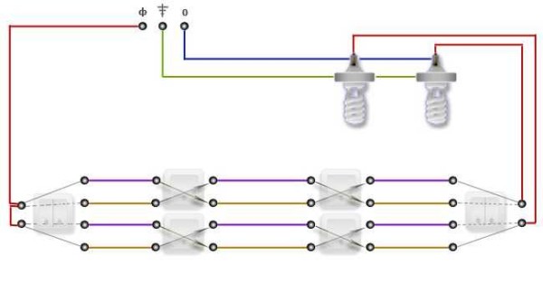
 Scheme of organizing on/off lamp for 5 points.
 If you remove one of the cross switches from this circuit, you get a 4-point option, and if you add one cross switch to it, you get a 6-point option.
Two-key pass-through switch: connection diagram
In order to control the operation of two lamps from several points, there are two-key pass-through switches. They have six contacts. The main thing is to identify common contacts. They are determined according to the same principle as when searching for a common contact in single-key pass-through switches.
In a circuit that uses two two-key pass-through switches, significantly more wires are used.
The phase wire is supplied to the inputs of both switches, and the other inputs of the switches are connected to one end of one and the other lamp. The free ends of the lamp are connected to the neutral conductor. The two outputs of one switch are connected to the two outputs of the second switch, and the other two outputs of that switch are connected to the other two outputs of the first switch.
 Wiring option for connecting two-key pass-through switches.
 If you want to control the operation of two lamps from three or four points, you will have to purchase two cross switches. Each pair of two-gang switch outputs is connected to one pair of one crossover switch. And so on, pair by pair, the outputs of the devices are connected to each other.
 Controlling the operation of two lighting lamps from four points.
 If you look at it, there is nothing complicated, especially when using single-key pass-through switches. As for two-key pass-through switches, everything here is much more serious and costly, both in terms of wires and switches. To be more precise, this scheme is less practical, but more expensive.


