DIY digital soldering station (ATmega8, C). DIY soldering station with hair dryer for atmega8
Digital soldering station. Why is it needed and what are its advantages? There are many reasons: some people are tired of peeling traces, some people heat up the soldering iron with a lighter or on gas because they cannot solder a massive part, some people have a spiral break through the body and get an electric shock, some people need to very accurately control the temperature of the soldering iron tip , and who just wants to switch to a modern SMD element base.What is the difference between a soldering station and a regular soldering iron, or even a soldering iron with a regulator? In the soldering station there is, in our terms, feedback. When the tip touches a massive part, the temperature of the tip drops, and the voltage at the thermocouple output decreases accordingly. This voltage drop, amplified by the op-amp, is sent to the microcontroller, and it immediately supplies more power to the heater, increasing the temperature of the tip (more precisely, the voltage at the output of the op-amp) to the level that is recorded in memory. After reading this article, collecting the necessary equipment, and not forgetting to flash the controller first, you will use your old, boring and imperfect soldering irons for the last time, moving on to a more professional level of soldering circuits. So, I present to your attention a homemade digital soldering station. Functionally, the circuit consists of two parts - a control unit and an indication unit.
In the author’s version, the 7805 stabilizer is connected to a diode bridge, the output from which goes to heat the soldering iron, but there is a minimum of 24 volts. Therefore, it is better to use for these purposes a lower voltage winding of the transformer, if available, or a separate power source, for which I used a charger from a mobile phone. If the charger produces a stable 5 volts, then you can refuse to use a stabilizer.

Almost all parts are placed on one board. and firmware taken from the radiokot website. You can download them in the archive. The diode bridge and electrolytic capacitor are located outside the board. In the center of the diode bridge there is a hole with which it is secured to the body of the soldering station. The electrolyte is soldered directly onto it.

Equipment: ATmega8, LM358, IRFZ44, 7805, loose powder, three-digit seven-segment LED indicator A-563G-11, five clock buttons (three are possible) and a five-volt beepper with a built-in generator. Element ratings:
R1 - 1M
R2 - 1k
R3 - 10k
R4 - 82k
R5 - 47k
R7, R8 - 10k
R indicator -0.5k
C3 - 1000mF/50v
C2 - 200mF/10v
C - 0.1mF
Q1 - IRFZ44
IC4 – 78L05ABUTR
I used different diode bridges, the main thing was to draw current. Transformers - TS-40. True, I only connect one half of the transformer, so it gets hot, but it has been working for a couple of years. In principle, you can use a simple one, with a power reserve, to avoid the use of coolers. In this case, it will be possible to use a compact, inexpensive plastic case. The plus of the beeper is connected to the 12th pin of the microcontroller (or to the 14th if the controller is used in a DIP package). The negative is connected to ground.

Technical characteristics of the soldering station. Temperature from 50 to 500 degrees, (heating to 260 degrees for about 30 seconds), two buttons +10 degrees and -10 degrees temperature, three memory buttons - long press (until blinking) - remembering the set temperature (EE), short - setting the temperature from memory. After power is applied, the circuit is in sleep mode, after pressing the button, the installation from the first memory cell is turned on. When you first turn on the temperature in memory is 250, 300, 350 degrees. The set temperature blinks on the indicator, then the tip temperature runs and then lights up with an accuracy of 1*C in real time (after heating, it sometimes jumps 1-2*C ahead, then stabilizes and occasionally jumps by +-1*C). 1 hour after the last manipulation of the buttons, he falls asleep and cools down (in fact, he may pass out earlier). If the temperature is more than 400*C, he falls asleep after 10 minutes (to preserve the sting). The beeper beeps when turned on, when buttons are pressed, when recording into memory, when the set temperature is reached, it warns three times before falling asleep (double beep), and when falling asleep (five beeps). After assembly, the soldering station must be calibrated. It is calibrated using the R5 trimmer and a thermocouple, which comes with many multimeters. I have DT-838. I checked it with an industrial thermocouple. I was pleased with the accuracy of the readings.
Fuzes:

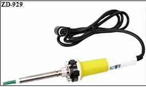
Now about soldering irons. In our homemade station, you can use soldering irons from soldering stations from different manufacturers. In my version I use the ZD-929 at 24 Volts and 48 Watts.
Here is the pinout of its connector:

And LUKEY, I don’t know the model, but also for this voltage:

Later it turned out that LUKEY was significantly inferior in quality and power. During its short period of operation, the thermocouple flew off. In addition, it is weaker than the ZD-929. The hatch connector is the same as a PS/2 computer, so I immediately cut it off and replaced it with RSh2N-1-17. It will be more reliable that way.

The heater resistance is 18 Ohms, the thermocouple resistance is 2 Ohms. The polarity of the thermocouple must be observed. “+” of the thermocouple goes to R3, “–” to ground. The polarity of the thermocouple can be determined with a tester by setting it to 200 mV and warming up the soldering iron with a lighter. So, we have switched to the latest installation technologies, what next? Now you need to read the operating rules, so as not to ruin expensive, but long-lasting stings.
1.
Multi-layer solder tips do not require (and do not allow) any sharpening.
2.
Unnecessarily high temperatures will shorten the life of the tip. Use the lowest possible temperature.
4.
During continuous operation, at least once a week, it is necessary to remove the tip and completely clean it of oxides. The solder on the tip should remain even when cold.
A few words about the “soft cellulose sponge”. You should buy it in the same place where you bought the soldering iron. But do not rush to poke the tip into it. Before that, you need to wet it, as a result of which it will swell, and squeeze it out. Now the sponge is ready for use. In extreme cases, you can use a cotton napkin instead of a sponge.
Here we come to the end. Now the most interesting part – photos of the finished devices.
Homemade station:

Upgraded to the curved tips of the local radio factory ZD-929 in a stand of two hard drives:

Lukey in a purchased stand. Visually, the stand is similar to a similar one from Pace (which is what I fell for when ordering), but instead of cast metal there is plastic:

The design was assembled and tested by: Troll
Discuss the article HOMEMADE SOLDERING STATION
DIY soldering station. How to assemble a soldering station with a hair dryer for little money.

It is often necessary to repair devices with SMD components (phones, radios, various modules), etc. The same USB connector on a phone (as often happens) is not so easy to re-solder with a regular soldering iron without damage. So it's time to start assembling the soldering station.

Below is a list of the main components that will be needed to assemble a “budget soldering station”.
Buy on AliExpress

The scheme is primitive. The author also offers the firmware source code in C++.
The author's printed circuit board is made for SMD resistors and capacitors. I decided to remake it for output components (partially). I separated the high-voltage part from the main board and assembled it separately.


I transferred the printed circuit board to PCB using the “LUT” technology and etched it with ferric chloride. I installed the transistor that controls the turbine on the hot air gun, KT805, and made sure to install it on a small heat sink.

Since this is a “budget version,” I decided not to buy the case, but to make it myself. I had a casing lying around, with fairly thick and high-quality plastic from an old German TV, and I decided to cut the walls and assemble a housing from it for a “soldering station.” Everything looks pretty good.


I trimmed the LEDs on the front panel so they wouldn't stick out.

I didn't buy a soldering iron either. I had a Chinese “soldering iron gun” with a burnt-out heater, and a handle from a Soviet soldering iron. I just took the sleeve - which holds the tip and the heater from the "soldering iron - gun" - and connected them together with the handle, bought a heater with a thermocouple and inserted it into it.


I got the transformer from a Soviet 25-volt tape recorder, and it’s quite suitable in terms of power. The diode bridge was assembled from KD202 diodes. I also installed active cooling (exhaust fan).


If you look at my board assembly in the photo, you will see a part that is not in the original seals. This is my “multivibrator”. Why is he needed there? Ehh.. I installed it for a buzzer (squeaker) because I didn’t have a buzzer with a built-in generator, and I really wanted a beeping sound. In fact, I don't recommend you do this! That's a lot of extra hesitation. It's easier to buy a buzzer with a built-in generator.
It is necessary to take into account that the author divided the power supply into digital and power. This is necessary so that the microcontroller does not have interference or any interference from the power part. So in the circuit there are TWO EARTHS and the digital part is powered by a separate stabilized 5 volt power supply. I, like the author, also decided to use a mobile phone charger.

We take the AVR UsbAsp programmer. We connect it to the PC and to the microcontroller.
There are a lot of diagrams of various soldering stations on the Internet, but they all have their own characteristics. Some are difficult for beginners, others work with rare soldering irons, others are not finished, etc. We focused specifically on simplicity, low cost and functionality so that every novice radio amateur could assemble such a soldering station.
What is a soldering station for?
An ordinary soldering iron, which is connected directly to the network, simply heats constantly with the same power. Because of this, it takes a very long time to warm up and there is no way to regulate the temperature in it. You can dim this power, but achieving a stable temperature and repeatable soldering will be very difficult.
A soldering iron prepared for a soldering station has a built-in temperature sensor and this allows you to apply maximum power to it when heating up, and then maintain the temperature according to the sensor. If you simply try to regulate the power in proportion to the temperature difference, then it will either warm up very slowly, or the temperature will fluctuate cyclically. As a result, the control program must necessarily contain a PID control algorithm.
In our soldering station, we, of course, used a special soldering iron and paid maximum attention to temperature stability.
Specifications
- Powered by 12-24V DC voltage source
- Power consumption, when powered 24V: 50W
- Soldering iron resistance: 12ohm
- Time to reach operating mode: 1-2 minutes depending on the supply voltage
- Maximum temperature deviation in stabilization mode, no more than 5 degrees
- Control algorithm: PID
- Temperature display on a seven-segment indicator
- Heater type: nichrome
- Temperature sensor type: thermocouple
- Temperature calibration capability
- Setting the temperature using the ecoder
- LED to display soldering iron status (heating/operating)
Schematic diagram
The scheme is extremely simple. At the heart of everything is the Atmega8 microcontroller. The signal from the optocoupler is fed to an operational amplifier with adjustable gain (for calibration) and then to the ADC input of the microcontroller. To display the temperature, a seven-segment indicator with a common cathode is used, the discharges of which are switched on through transistors. When rotating the BQ1 encoder knob, the temperature is set, and the rest of the time the current temperature is displayed. When turned on, the initial value is set to 280 degrees. Determining the difference between the current and required temperature, recalculating the coefficients of the PID components, the microcontroller heats up the soldering iron using PWM modulation.
To power the logical part of the circuit, a simple 5V linear stabilizer DA1 is used.

Printed circuit board
The printed circuit board is single-sided with four jumpers. The PCB file can be downloaded at the end of the article.


List of components
To assemble the printed circuit board and housing, you will need the following components and materials:
- BQ1. Encoder EC12E24204A8
- C1. Electrolytic capacitor 35V, 10uF
- C2, C4-C9. Ceramic capacitors X7R, 0.1uF, 10%, 50V
- C3. Electrolytic capacitor 10V, 47uF
- DD1. Microcontroller ATmega8A-PU in DIP-28 package
- DA1. L7805CV 5V stabilizer in TO-220 package
- DA2. Operational amplifier LM358DT in DIP-8 package
- HG1. Seven-segment three-digit indicator with a common cathode BC56-12GWA. The board also provides a seat for a cheap analogue.
- HL1. Any indicator LED for a current of 20 mA with a pin pitch of 2.54 mm
- R2,R7. Resistors 300 Ohm, 0.125W - 2 pcs.
- R6, R8-R20. Resistors 1kOhm, 0.125W - 13pcs
- R3. Resistor 10kOhm, 0.125W
- R5. Resistor 100kOhm, 0.125W
- R1. Resistor 1MOhm, 0.125W
- R4. Trimmer resistor 3296W 100kOhm
- VT1. Field effect transistor IRF3205PBF in TO-220 package
- VT2-VT4. Transistors BC547BTA in TO-92 package - 3 pcs.
- XS1. Terminal for two contacts with pin spacing 5.08 mm
- Terminal for two contacts with pin spacing 3.81 mm
- Terminal for three contacts with pin spacing 3.81 mm
- Radiator for stabilizer FK301
- Housing socket DIP-28
- Housing socket DIP-8
- Power switch SWR-45 B-W(13-KN1-1)
- Soldering iron. We will write about it later
- Plexiglas parts for the body (cutting files at the end of the article)
- Encoder knob. You can buy it, or you can print it on a 3D printer. File for downloading the model at the end of the article
- Screw M3x10 - 2 pcs.
- Screw M3x14 - 4 pcs.
- Screw M3x30 - 4 pcs.
- Nut M3 - 2 pcs.
- M3 square nut – 8 pcs
- M3 washer - 8 pcs
- M3 locking washer – 8 pcs
- Assembly will also require installation wires, zip ties and heat shrink tubing.
This is what a set of all the parts looks like:

PCB installation
When assembling a printed circuit board, it is convenient to use the assembly drawing:

The installation process will be shown and commented on in detail in the video below. Let us note only a few points. It is necessary to observe the polarity of electrolytic capacitors, LEDs and the direction of installation of microcircuits. Do not install microcircuits until the case is completely assembled and the supply voltage has been checked. ICs and transistors must be handled carefully to avoid damage from static electricity.
Once the board is assembled, it should look like this:

Housing assembly and volumetric installation
The block wiring diagram looks like this:

That is, all that remains is to supply power to the board and connect the soldering iron connector.
You need to solder five wires to the soldering iron connector. The first and fifth are red, the rest are black. You must immediately put a heat-shrinkable tube on the contacts, and tin the free ends of the wires.
The short (from the switch to the board) and long (from the switch to the power source) red wires should be soldered to the power switch.
The switch and connector can then be installed on the front panel. Please note that the switch may be very difficult to engage. If necessary, modify the front panel with a file!


The next step is to put all these parts together. There is no need to install the controller, operational amplifier or screw on the front panel!

Controller firmware and setup
You can find the HEX file for the controller firmware at the end of the article. The fuse bits should remain factory, that is, the controller will operate at a frequency of 1 MHz from the internal oscillator.
The first power-up should be done before installing the microcontroller and operational amplifier on the board. Apply a constant supply voltage from 12 to 24V (red should be “+”, black “-”) to the circuit and check that there is a 5V supply voltage between pins 2 and 3 of the DA1 stabilizer (middle and right pins). After this, turn off the power and install the DA1 and DD1 chips into the sockets. At the same time, monitor the position of the chip key.
Turn the soldering station back on and make sure all functions are working correctly. The indicator displays the temperature, the encoder changes it, the soldering iron heats up, and the LED signals the operating mode.
Next, you need to calibrate the soldering station.
The best option for calibration is to use an additional thermocouple. It is necessary to set the required temperature and control it on the tip using a reference device. If the readings differ, then adjust the multi-turn trimmer resistor R4.
When setting, remember that the indicator readings may differ slightly from the actual temperature. That is, if you set, for example, the temperature to “280”, and the indicator readings deviate slightly, then according to the reference device you need to achieve exactly a temperature of 280°C.
If you don’t have a control measuring device at hand, you can set the resistor resistance to about 90 kOhm and then select the temperature experimentally.
After the soldering station has been checked, you can carefully install the front panel so that the parts do not crack.


Video of work
We made a short video review
…. and a detailed video showing the assembly process:
I thought for a long time whether to write an article about this homemade product or not. On the Internet you can probably count a dozen articles on this scheme. But since, in my opinion, this particular circuit design solution is the most successful, I am sharing the design with you, dear visitors of the Technoreview website. I would like to immediately thank the author of the diagram for the work done, and for the fact that he posted it for public use. The soldering station is quite simple to manufacture and is very necessary in amateur radio practice.
When I first started my journey as a radio amateur, I didn’t think about anything. Soldered with a powerful 60 watt soldering iron. Everything was done with overhead mounting and thick wires. Over the years, having gained a little experience, the tracks became thinner and the details became smaller. Soldering irons of lower power were purchased accordingly. I once purchased a soldering iron from the LUKEY-702 soldering station with a maximum power of 50 watts and a built-in thermocouple. I picked up the diagram for assembly right away. Simple and reliable, with a minimum of parts.
Diagram of a homemade soldering station


Parts list for the circuit:
- R1 - 1M
- R2 - 1k
- R3 - 10k
- R4 - 82k
- R5 - 47k
- R7, R8 - 10k
- R indicator -0.5k
- C3 - 1000mF/50v
- C2 - 200mF/10v
- C - 0.1mF
- Q1 - IRFZ44
- IC4 – 78L05ABUTR


The power transformer was taken from a record player. His name is TS-40-3. I didn’t rewind anything. All the corresponding voltages are already there. To power the soldering iron itself, two windings were connected in parallel. It produces about 19 volts. That's enough for us. To do this, on this transformer model you need to place jumpers between transformer terminals 6 and 8, as well as 6’ and 8’ on the other coil. Remove the voltage from pins 6 and 6’.

To power the microcontroller of the soldering station control unit and the op-amp, we need a voltage from 7.5 to 15 volts. Of course, you can go up to 35, but this will be the limit for the 78L05 stabilizer chip. It will get very hot. To do this, I connected the windings in series. The resulting voltage was 12 volts. Two wires are soldered to pin 8 of the transformer. Unsolder what is thinner and transfer it to a free terminal. The jumper must be placed on the 10th terminal of the transformer and the sealed wire. The voltage is removed from pins 10' and 12. The above is only for the TS-40-3 transformer.

Power diodes B1 are used KD202K. Just suitable for this purpose. To power the MK, I took a small-sized diode assembly B2. E30361-L-0-8-W with a common cathode was used as LED indicators. I also designed my own printed circuit board for my own indicator. It turned out to be double-sided. One-sided could not. Too many jumpers. The board is not the best, but it has been tested and works. I also re-soldered the connector on the soldering iron itself. His standard one is no good. At first, the boozer was not provided on the board. I installed it after, but the board in the archive was fixed.


The father and mother selected the best connector from the available trash. I also want to say something about the IRFZ44 field-effect transistor. For some reason he didn’t want to work for me. It immediately burned out when turned on. At the moment, IRF540 has been installed for about a year. It hardly gets warm. It doesn't need a big radiator.
Soldering station - case manufacturing

So, the housing of the soldering station. It’s good when you go to a store and there is a selection of ready-made cases. Unfortunately, I don't have that luxury. But I don’t really want to look for all sorts of boxes for who knows what, and then think about how to stuff everything in there. The body was bent from tin. Then I marked and drilled all the holes and painted them with spray paint. I sealed the hole for the indicator with a piece of plastic from a black beer bottle. The buttons are made from Soviet housings of KT3102 transistors in an iron case and the like. You also need to calibrate the temperature readings using resistor R5 and the thermocouple of the multimeter. After assembly and testing, I secured all the wires with plastic fasteners. Then I screwed on the top cover of the case. The station is ready for operation. Happy assembly everyone. The soldering station was made by Bukhar.
Which is one of the most important tools in the kit of an engineer whose work is related to electronics. This is what you probably love and hate, the soldering iron. You don’t have to be an engineer to suddenly need one: it’s enough to just be a craftsman who repairs something at home.
For basic applications, a regular soldering iron that you plug into a power outlet works well; but for more delicate work like repairing and assembling electronic circuits, you'll need a soldering station. Temperature control is critical to avoid burning components, especially ICs. Additionally, you may also need it to be powerful enough to maintain a certain temperature when you solder something to a large earth pad.
In this article we will look at how you can assemble your own soldering station.
Development
When I developed this soldering station, several key properties were important to me:
- portability- this is achieved through the use of a switching power supply, instead of a conventional transformer and rectifier bridge;
- simple design- I don’t need LCD displays, extra LEDs and buttons. I just needed a seven-segment LED indicator to show the set and current temperature. I also wanted a simple temperature selector knob (potentiometer) without a potentiometer for fine adjustment, as this is easy to do using software;
- versatility- I used a standard 5-pin plug (some kind of DIN type) so that it would be compatible with Hakko and similar soldering irons.
How it works
First of all, let's talk about PID (proportional-integral-derivative, PID) controllers. To make everything clear at once, let's look at our particular case with a soldering station. The system constantly monitors the error, which is the difference between the set point (in our case, the temperature we need) and our current temperature. It adjusts the output of the microcontroller, which controls the heater using PWM, based on the following formula:
As you can see, there are three parameters K p , K i and K d . The parameter K p is proportional to the current error. The parameter K i takes into account errors that have accumulated over time. The parameter K d is a prediction of the future error. In our case, for adaptive tuning we use Brett Beauregard's PID library, which has two sets of parameters: aggressive and conservative. When the current temperature is far from the set value, the controller uses aggressive parameters; otherwise, it uses conservative parameters. This allows us to achieve fast heating times while maintaining accuracy.
Below is a schematic diagram. The station uses an 8-bit ATmega8 microcontroller in a DIP package (you can use an ATmega168-328 if you have them on hand), which is very common, and the 328 variant is found in the Arduino Uno. I chose it because it is easy to flash using the Arduino IDE, which also has ready-to-use libraries.
The temperature is read using a thermocouple built into the soldering iron. We amplify the voltage generated by the thermocouple by about 120 times using an op-amp. The output of the op-amp is connected to the ADC0 pin of the microcontroller, which turns the voltage into values between 0 and 1023.
The setpoint is set using a potentiometer, which is used as a voltage divider. It is connected to the ADC1 pin of the ATmega8 controller. The 0-5 volt range (potentiometer output) is converted to 0-1023 values using an ADC and then to 0-350 degrees Celsius values using the "map" function.
List of components
| Designation | Denomination | Quantity |
|---|---|---|
| IC1 | ATMEGA8-P | 1 |
| U1 | LM358 | 1 |
| Q1 | IRF540N | 1 |
| R4 | 120 kOhm | 1 |
| R6, R3 | 1 kOhm | 2 |
| R5, R1 | 10 kOhm | 2 |
| C3, C4, C7 | 100 nF | 3 |
| Y1 | 16 MHz | 1 |
| C1, C2 | 22 pF | 2 |
| R2 | 100 Ohm | 1 |
| U2 | LM7805 | 1 |
| C5, C6 | 100 µF (less is possible) | 2 |
| R7, R8, R9, R10, R11, R12, R13, R14 | 150 Ohm | 8 |
This is a list of components exported from KiCad. In addition, you will need:
- a clone of the Hakko soldering iron, the most popular in Chinese online stores (with a thermocouple, not a thermistor);
- power supply 24 V, 2 A (I recommend using a switching power supply, but you can use a transformer with a bridge rectifier);
- potentiometer 10 kOhm;
- 5 pin aircraft type electrical plug;
- electrical connector installed on the rear panel to supply 220 V power;
- printed circuit board;
- power switch;
- 2.54 mm pin connectors;
- a lot of wires;
- Dupont connectors;
- body (I printed it on a 3D printer);
- one triple seven-segment LED indicator;
- AVR ISP programmer (you can use Arduino for this).
Of course, you can easily replace the LED indicator with an LCD display or use buttons instead of a potentiometer, after all, this is your soldering station. I've outlined my design, but you can do it your own way.
Assembly Instructions
First, you must make the PCB. Use the method you prefer; I recommend transferring the board design with laser printer toner, as this is the easiest way. Also, I have the PCB extended because I wanted it to be the same size as the power supply so I could mount it on top of it. Feel free to modify the board, you can download the project files and edit them using KiCad. After making the PCB, solder all the components to it.
Be sure to install a switch between the power supply and the power connector. Use relatively thick wires for the connections between the power supply and the PCB and the output connector to the drain of the MOSFET (point H on the board) and ground on the PCB. To connect the potentiometer, connect the 1st pin to the +5V line, the 2nd to the POT point, and the 3rd to ground. Please note that I am using a common anode LED, which may be different from what you have. You will have to change the code a little, but all instructions in the program code are commented. Connect pins E1-E3 to the common anodes/cathodes, and pins a-dp to the corresponding pins of your indicator. For more detailed information, see the technical description on it. Finally, install the output connector of the soldering station and solder all connections to it. The picture above should help you, with the diagram and pinout of the connector.
Now comes the fun part, loading the code. To do this you will need the PID library (link to GitHub).
#include// Display the set value if (abs(newSetpoint - Setpoint) > 3) ( Setpoint = newSetpoint; temperature = newSetpoint; lastupdate = millis(); ) double gap = abs(Setpoint - Input); // Distance from the set value if (gap
If you don't have a programmer, you can use Arduino. Connect your Arduino (Uno/Nano) board to your computer, go to File → Examples → ArduioISP and load it. Then go to Tools → Programmer → Arduino as ISP. Connect your board to the Arduino board, download the sketch, and then select Sketch → Upload via Programmer.
That's all. Now you can enjoy working with a soldering station assembled with your own hands.
Calibration
But no, that's not all. Now we need to calibrate it. Since the heaters and thermocouples in soldering irons may vary, especially if you are using a non-genuine Hakko soldering iron, we need to calibrate the soldering station.
First, we need a digital multimeter with a thermocouple to measure the temperature of the soldering iron tip. Once you have measured the temperature, you need to change the default value "510" in the map(Input, 0, 510, 25, 350) line of code using the following formula:
where TempRead is the temperature that is displayed on your digital thermometer and TempSet is the temperature that you have set on your soldering station. This is just a rough setting, but it should be sufficient since you don't need extreme precision when soldering. I used Celsius, but you can change it to Fahrenheit in the code.
Printing the body on a 3D printer (optional)
I designed and printed a case that could house a switching power supply and PCB to make everything look neat. Unfortunately, to use this case you will need to find the exact same type of power supply. If you have a suitable source and want to print the enclosure, or if you want to customize it to suit your requirements, you can download the attached files. I printed at 20% infill and 0.3 layer thickness. You can use higher infill levels and lower layer heights if you have the time and patience.
Conclusion
That's all! I hope the article was useful. Below are all the necessary materials.


