Basic CB antennas. Basic CB antennas Basic antenna 27 MHz 5 8
This page presents stationary antennas for CB radio stations 27 MHz. Here you will see only original products from various brands.
To find out about the compatibility of antennas and your walkie-talkie, read the product descriptions or ask our consulting engineer: he will be happy to recommend the best option for you.
Here are just a few examples of the differences in performance between fixed 27 MHz antennas:
- Alan ENERGY ½ . This is an antenna with retractable elements, mounted on a mast and equipped with a system against water infiltration. It is compatible with Alan 78 Plus, Alan 100 Plus, Alan 42, Alan 48 Excel, Alan 48 Plus, Midland 278 and Midland 77/120/ESP2 stations. Its main characteristics are as follows: SWR 1/1.2, gain 3 dBi, maximum power 500 W, length 5.75 m;
- Sirio 2008 type 5/8. The antenna pole is made from durable telescopic aluminum tubes, and the top section is equipped with an antistatic “globe”. It is equipped with eight counterweights, and the coil is made of copper wire and protected by a plastic casing. Height 6.1 m, maximum power 1000 W;
- We can also provide outdated options, for example, President Black Pirate 5R. It is no longer in production, but perfectly supports 2500 watts of power. Its height is 5.27 m, and it is made of carbon fiber.
We will be happy to advise you on the range and characteristics of basic antennas for the civil range. Call!
In the CB range, antennas with vertical polarization are most widespread. This is due to the fact that CB radios are widely used to communicate with moving objects, and it is very difficult to place an effective horizontal polarization antenna on a car. For the same reason, antennas with a circular radiation pattern in the horizontal plane, which work equally well in any direction, are chosen as the base ones.
GP with length l/4
The most widely used antennas in this group are the “Ground Plane” type antennas, or “GP” for short, shown in Fig. 10.2.
The antenna has a whip design, convenient for placement both on the roof of a building and on a car. It is simple and, at the same time, quite effective. The length of the pins (l/4) for operation in the 27 MHz range depends on the diameter of the tubes and is indicated in Table 1
Table 1. Lengths of GP antenna elements
For normal operation of the antenna, it is equipped with three counterweights, which can be made from a tube or antenna cord. The length of the counterweights is chosen equal to or 2.5% greater than 2/4l. For the CB range, it can be taken as equal to 275 cm. The input impedance of the antenna depends on the angle between the counterweights and the mast: the smaller this angle (the counterweights are pressed against the mast), the greater the resistance. To obtain an input impedance of 50 Ohms, the angle is selected to be 30-45 degrees. The radiation pattern in the vertical plane has a maximum at an angle of 30 degrees to the horizon. The antenna gain is approximately equal to the gain of a vertical half-wave dipole. Best performance is achieved with a mast height of about 6 m.
This antenna has the most broadband of all GP options. If, after installation, the minimum SWR of the antenna turns out to be slightly higher or lower than the frequency of channel 20 of grid C, the length of the pin must be increased or decreased accordingly. After tuning the antenna to resonance, the minimum SWR at medium frequency is achieved by changing the angle of installation of the counterweights.

The disadvantage of this design is the lack of connection between the pin and the mast, which requires additional measures for lightning protection and protection against static electricity. The simplest method of protection is to use a short-circuited cable made of a cable with a length of l/4, connected to the feeder using a tee. The cable provides a DC connection between the central core of the feeder and the grounded braid and does not affect the antenna matching. The cable connection diagram is shown in Fig. 3
The length of the cable is calculated taking into account the shortening factor of the cable used and is about 2 m.
GP with length l/2
In Fig. Figure 10.4 shows the design of a half-wave antenna GP with a length of l/2. Compared to the antenna described above, it has twice the length of the rod, which places increased demands on ensuring the wind strength of the structure. The antenna does not need counterweights, the role of which is played by the mast, and its radiation pattern in the vertical plane is more closely pressed to the horizon, which improves the conditions for radio exchange with remote correspondents. Since the antenna has a high input impedance, the cable is connected to it through a matching high-frequency transformer. The base of the pin is connected to the grounded mast through a matching transformer, which automatically solves lightning protection and static problems. The antenna gain compared to a half-wave dipole is about 4 dB.
Typical matching transformer data:
Frame diameter - 30mm
Wire diameter - (PEV-2) 1mm
Number of turns - 6
Branch from 1.5 - turns
counting from (cold) grounded
coil output
The cable is connected centrally
residential to the outlet.
The antenna sheet is connected to the "hot"
coil output.
GP with length 5/8l
The most effective for long-distance communications is GP length 5/8l. Its design is shown in Fig. 10.5. It is slightly longer than the half-wave antenna, and the feeder cable is connected to the matching inductance located at the base of the vibrator. This type of antenna requires the use of at least three counterweights with a length of (0.1-0.2)l located in a horizontal plane. Antennas of this type are narrower than half-wave antennas, and therefore require more careful tuning. Tuning at the middle frequency is achieved both by changing the length of the pin and by adjusting the value of the matching inductance. The required input impedance is achieved by selecting the point at which the cable is connected to the matching coil. The gain of this antenna is 5-6 dB, the maximum of the radiation pattern is located at an angle of 15 degrees to the horizon. The pin of this design is also grounded to the mast through a matching coil. Approximate data for a matching coil for a 50 Ohm cable impedance:
frame diameter - 18 mm,
wire diameter - 1.5 mm,
number of turns - 22,
winding pitch -2.5 mm,
branch - from the 9th turn,
counting from the grounded end of the coil.
Installing an antenna on a roof can greatly affect its performance. General recommendations are the following:
- It is advisable to place the antenna base no lower than 3 m from the roof plane;
- there should be no metal objects or structures near the antenna (for example, television antennas, wires, etc.);
- It is advisable to install the antenna as high as possible;
- for normal operation of the station, the nearest base CB antenna should not be located closer than 200 m.
The transmission efficiency of an antenna is higher, the lower the ohmic losses in its elements. Therefore, the best material for antenna elements are copper tubes, however, the use of aluminum (duralumin) tubes (due to the high specific gravity and low strength of copper) can be considered an acceptable compromise.

If it is necessary to expand the frequency band, the diameter of the tubes is increased, or tubes with a ribbed outer surface are used. Since the current flowing through the antenna pin decreases towards its upper end, the diameter of the upper part of the pin can be reduced without degrading its parameters. One of the simplest means of expanding the frequency band of long whip antennas is the use of a bushing with four whiskers about 100 mm long and 4-5 mm in diameter, fixed in the upper part of the whip (Fig. 10.6). In this case, the resonant frequency of the antenna decreases and the length of the pin will have to be reduced somewhat. When the antenna is operating for transmission, quite large currents flow through it, so it is necessary to ensure a very good connection of all elements to each other and take care of their protection from corrosion.
Currently, factory-made CB antennas (Fig. 10.7) are available for sale, both domestic and imported, lightweight, elegantly made. As evidenced by the experience of their operation, in connections of elements that are made with self-tapping screws, electrical contact is quickly lost under the influence of wind. The design of pins with tie clamps is more reliable. Almost all types of industrial antennas require additional sealing to prevent water from getting inside the tubes, onto matching transformers, coils and cable terminations, which leads to irreversible consequences.

Rice. 10.8 GP antenna without mast
If on the roof of your house there is a fairly high elevator booth, a television antenna or an extension more than 5 meters high, then the GP antenna can be installed using a nylon guy rope (Fig. 10.8) without a mast. In addition to the nylon cord and RK-50 cable, you will need 4 more insulators of any type. The end of the 2.7 m cable is freed from the outer insulation and braid, the braid is unraveled and twisted into 4 approximately identical “braids”. Counterweights are attached to them. Counterweights can be made from any copper (in extreme cases, even aluminum) wire, which is screwed (or soldered) to the “pigtails”. The length of the counterweights should be 2.7 m. Insulators are fixed at the ends of the counterweights, which are attached to wire or nylon guys. The end of the cable section freed from the braid is attached to the nylon cord behind the polyethylene insulator so that it does not come off due to gusts of wind. The counterweights are moved to the sides evenly in a circle, the guy ropes are fixed to the roof (for example, tied to bricks). Try to select the length of the guys so that there is an angle of about 45° between the counterweight wire and the vertical. The joints and the place where the cable exits the braid are carefully sealed with plasticine so that water does not get under the braid.
This antenna is fully consistent in its characteristics with the classic GP antenna with a length of l/4. It is very convenient to install such an antenna in the field between two trees; you just need to prepare the cable and counterweights with guys in advance, and even short dry sticks will work as insulators at the ends of the counterweights (see Fig. 10.9), because at a frequency of 27 MHz it's a good insulator.
CB radio communication for everyone
For many years, there has been an opinion all over the world about the increased efficiency of vertical antennas with a radiator length of 5/8λ. It is credited with a low radiation angle, i.e. the tilt of the main lobe of the radiation pattern is close to the horizon. After all, in this case, the energy is concentrated along the surface of the earth, which is favorable for the radio communication range.
Sellers of CB equipment (27 MHz) and professional equipment are very fond of using this legend. At the beginning of my professional career, I did not hesitate to advertise 5/8λ antennas due to this property. Indeed, many practical experiments during long-distance radio communications have noted an increased signal level when using a 5/8λ compared to the classic 1/4λ GP antenna.
These qualities manifested themselves, as a rule, on long-distance radio paths at 27 MHz, for example, Moscow - Sydney (Australia) by a reflected beam, or in the near zone, during the propagation of a spatial wave, for example, Moscow - Petushki (about 100 km). At the same time, the signal at 5/8λ was received, albeit weakly, and at 1/4λ there was not even a hint of the presence of a radio station. In this case we are talking about a base antenna about 6 meters long and counterweights less than 1/4λ.
More than 10 years have passed since then; our company has long stopped producing 27 MHz antennas, having mastered the professional communications equipment market. The antennas we develop always go through measuring the radiation pattern and gain, and then one day, not having a reference antenna at 380 MHz, I decided to make a 5/8, as the simplest and with known characteristics.
This is where I doubted this fame. When I measured the DH in the vertical plane, I did not see anything similar to what is printed in books and magazines. 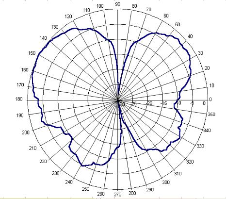
To my surprise, the synthesis in the MMANA program confirmed my practical results. The main petal was raised high up, at approximately an angle of 40° to the horizon. 
It is clearly visible that there is also a dip towards the horizon. A more detailed measurement of the amplitude-phase distribution along the antenna structure showed insufficient cutoff of surface currents on the feeder. 
A22-70cm Conventional half-wave coaxial dipole at a frequency of 433 MHz. 
This leads to the conclusion that one level of cutting counterweights or cups is not enough. However, there is another method to correctly distribute energy, namely, to allow it to be emitted by a larger useful surface in the desired phase. This is proven by the practical pattern of a simple collinear antenna consisting of two emitters and one level of counterweights 
The main lobe of the pattern of such an antenna is clearly pronounced and directs the energy strictly along the horizon. 
The “A” series antennas produced by our company, including new ones, have these characteristics
I want to tell you about my method of making a light basic CB antenna from a fiberglass fishing rod. In order to place the entire matching circuit inside the fishing rod, we take the most “compact” circuit from the point of view of the matching coil.
Pay attention to the capacitor C1, its operating voltage must be at least 500 volts, taking into account that we will not use the transmitter power anymore 10 Watt.
In principle, you can secure the fishing rod to the mast with simple nylon ties, but I propose a more reliable method. We weld together a strip of metal and a corner of arbitrary convenient sizes, as shown in the photo below.

A water pipe will be used as the base of the side extension, to which our corners will be welded. Subsequently, this pipe will be inserted into the mast and bolted there.

We assemble the coordination scheme using wall-mounted installation. We will use a thick copper stranded wire as a radiating element.

We fix the assembled structure inside the fishing rod in any available way. Having previously cut out a window in the base for adjusting the SWR. The fishing rod itself is attached to the stem using car clamps.


To obtain a wider operating band, you can attach a small capacitive load to the tip of the antenna.

We adjust the SWR at an average frequency of 27.200 MHz by compressing and stretching the coil turns.

After final adjustment of the antenna, you should seal the “tuning” window with electrical tape and fill it with glue; you should also fill the joints of the knees with glue.


The antenna installed at a low altitude showed good results when working over long distances.
0 Users and 1 Guest are viewing this topic.


